 electronicsworkshops

Introduction
Magnetic sensors are widely used in modern electronic systems for detecting the presence of magnets without requiring physical contact. In this project, we will design a magnetic sensor using the S411A Hall Effect sensor, a compact and reliable device that converts changes in a magnetic field into a digital output signal. The circuit is simple, requires only a few components, and is an excellent project for beginners, students, and electronics enthusiasts who want to learn about magnetic field sensing and PCB design.
Whether you're building a proximity detector, door sensor, position detector, or automation project, the S411A Hall Effect sensor offers a reliable and low-cost solution.
For Full Project:
https://electronicsworkshops.com/design-a-magnetic-sensor-using-s411a/
For Best Electronics Calculator:
https://numericalcalculator.com/
What is a Hall Effect Sensor?
A Hall Effect sensor is a semiconductor device that detects magnetic fields by measuring the Hall voltage generated when a magnetic field passes through the sensor. Unlike mechanical switches, Hall Effect sensors have no moving parts, making them more durable, reliable, and suitable for high-speed switching applications.
- Hall Effect sensors are commonly used in:
- Door and window security systems
- Speed detection
- Position sensing
- Motor control
- Robotics
- Automotive electronics
- Industrial automation
- Consumer electronics
Why Choose the S411A Hall Effect Sensor?
The S411A is a digital Hall Effect sensor designed for accurate magnetic field detection. It provides a clean digital output when a magnetic field of sufficient strength is present, making it ideal for switching and sensing applications.
Advantages of the S411A
- Compact TO-92 package
- Digital output
- High sensitivity
- Low power consumption
- Fast response time
- Reliable operation
- Wide operating voltage range
- Easy to interface with LEDs and microcontrollers
Pin Out of S411A
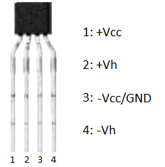
The S411A Hall Effect sensor is available in a compact 4-pin SIP (Single Inline Package), with each pin serving a specific function for magnetic field detection. Pin 1 (+VCC) is the positive power supply input, which powers the sensor using the recommended operating voltage. Pin 2 (+Vh) is the positive Hall voltage terminal, providing access to the internal Hall element for signal processing in certain applications. Pin 3 (−VCC/GND) serves as the ground or negative power supply connection, completing the power circuit. Pin 4 (−Vh) is the negative Hall voltage terminal, which works together with Pin 2 to generate the Hall voltage when a magnetic field is present. As a magnetic field passes through the sensor, a small Hall voltage is produced between the +Vh and −Vh terminals, and this signal can then be amplified or processed by external circuitry to detect the presence and strength of the magnetic field. This pin configuration makes the S411A well suited for magnetic sensing, position detection, speed measurement, and industrial automation applications.
Circuit diagram
The circuit shown is a simple magnetic sensor module built around the SS411A Hall Effect sensor, designed to detect the presence of a magnetic field and provide a digital output. The module operates from a +5 V power supply, which is connected through the P1 header. The three pins of the header provide +5 V, Ground (GND), and the Output (OUT) signal, making it easy to interface the module with a microcontroller such as an Arduino, ESP32, or Raspberry Pi. The SS411A Hall Effect sensor (U1) continuously monitors the surrounding magnetic field. When a magnet of the correct polarity is brought close to the sensor, the internal Hall element detects the magnetic flux and changes the state of the output pin, producing a digital signal that can be used to trigger LEDs, relays, alarms, or other electronic circuits.
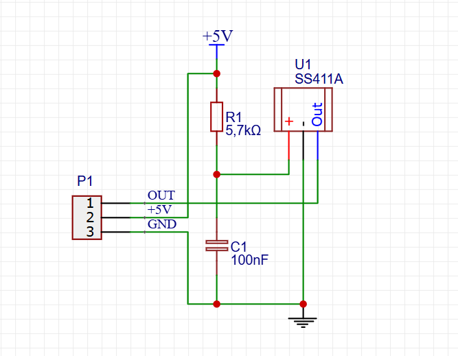
To ensure stable and reliable operation, the circuit includes a 5.7 kΩ pull-up resistor (R1) connected between the +5 V supply and the sensor's output....
Read more »