JP Gleyzes
Description
The teleinfo component allows you to retrieve data from a French electrical counter using Teleinformation. It works with Linky electrical counter but also legacy EDF electrical counter.
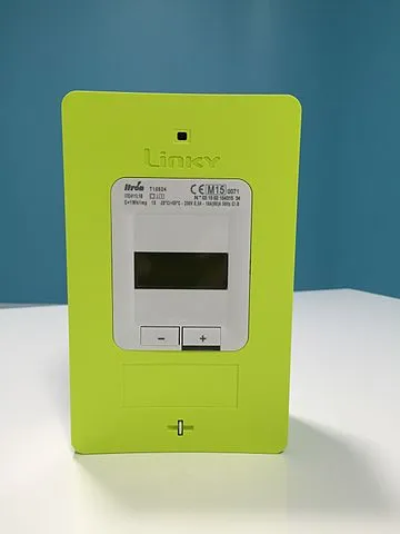
This project is a DIY open-source Teleinfo (TIC) decoder for French Linky electricity meters, powered by an ESP32. Unlike commercial Zigbee modules which are self-powered and forced to limit their data transmission frequency to avoid power crashes, this board is independently powered.
It reads the Linky TIC stream continuously in real-time and publishes the data instantly via MQTT to Home Assistant.
Key Features:
- Real-time updates: No polling limits or delay, ideal for reactive home automation.
- Native Home Assistant Discovery: Plug-and-play integration via MQTT Discovery (automatic entities creation for energy, power, current, and voltage).
- Robust isolation: Optocoupler circuit to safely isolate the Linky meter from the ESP32
This simple electronic assembly with an optocoupler and a resistor could let you retrieve detailed power consumption or power production. There are plenty of examples on the web. But the main reference regarding linky teleinfo was provided by Charles on his blog a few years ago.
Schematics
I have reproduced Charles'design and coupled it to my favorite ESP32 micro controller !
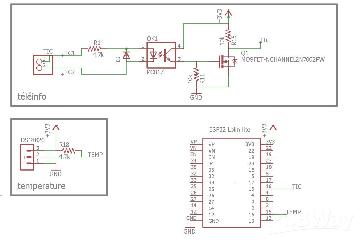
This schemactic seems simple (and it is) but needs clarifications !
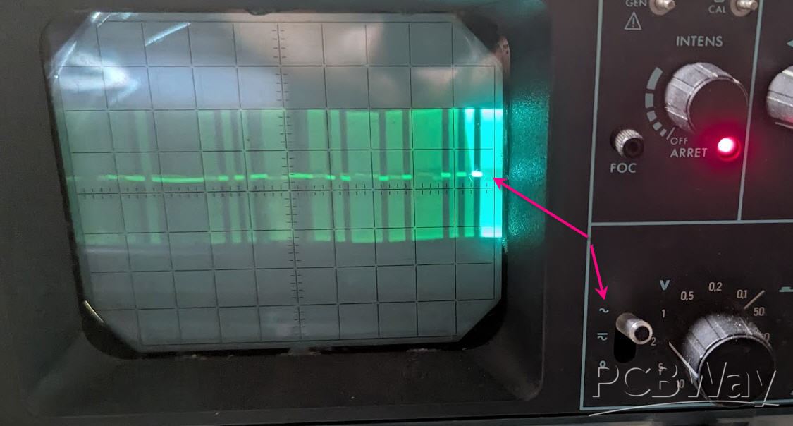
TIC signal is a 50kHz modulated UART signal, so that when plugging a scope you will recognize the modulation but not the bits !
The opto is there to isolate the MCU from this AC 10V TIC. Furthermore, the power delivered by the linky is very limited by specification
(ERDF-NOI-RES_13E) Linky can deliver less than 130 mW meaning that R14 resistor has to be relatively high (2k to 4.7k is the sweet spot).
This will protect the linky but also the LED of the optocoupler.
Power delivered by the opto is thus also weak ; and R13 cannot be too small if you want a clean demodulated signal. 10k is the sweet spot (4.7k does not work on my linky !)
Finally the serial signal must be amplified to get the logic level of your MCU. Q1 mosfet does the trick ! (Any Mosfet will work)
As this device will be integrated into my Home Assistant system, I have added a DS18B20 temperature sensor to monitor my garage ! This is of course totally optionnal.
PCB
The PCB was designed to enter into the linky (under the green cover) and with only the USB plug accessible below it. The system will thus be totally hidden under the cover, but you can plug a USB phone charger to power it !
The ESP32 goes on the top side, while all the other components go to the bottom side.
PCB can be bought at PCBWay directly from this project page.
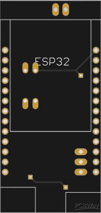
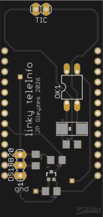
It is "tiny" but not compact, so that soldering is easy.
The PCB was kindly sponsored by PCBWay and is as usual of excellent quality.

and if you are new to PCBWay please use this affiliated link : https://pcbway.com/g/o35z4O
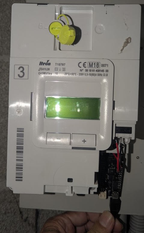
Result is a clean and compact setup which can be hidden into the linky
And when closed you can just power the board !
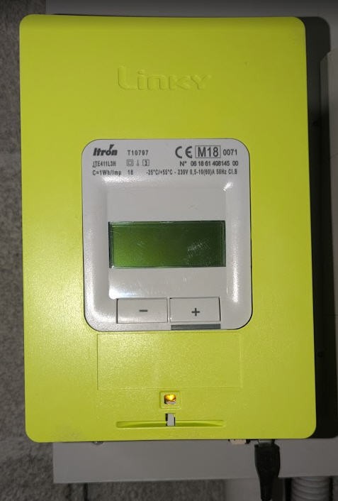
Firmware
You can download the source code on my Github pages
Firmware is simple to understand and is divided onto two parts
- TIC signal decoding
- Home Assistant MQTT integration
TIC decoding
Not too much to say here ! I only have "TIC Historique" mode available on my Linky, so decoding is done with this historical mode where only a few (but most interesting) parameters are available : current, power and total index.
Read the code, only a few lines are needed !
only two Important remarks :
- all characters are coded with 7E1 parity, so bit masking is needed
- once read, the full line must be checksummed and discarded if this checksum is not good
MQTT integration
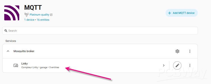
This is much more interesting ! Our Linky will be automatically discovered by Home Assistant as a MQTT device including 3 entities
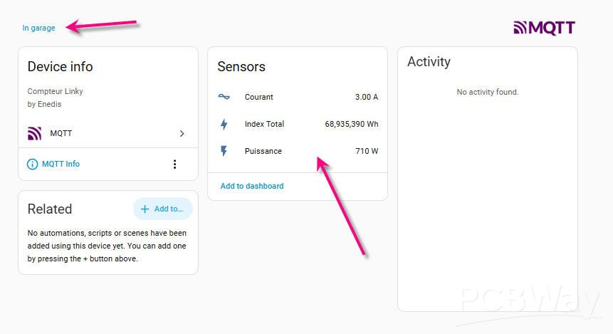
This device has been manually associated to my garage area and it contains the three parameters sent by the ESP32 (together with default icons for current power and energy !)
We achieve this behavior by sending "discovery messages" during boot time (and whenever we loose the connection with MQTT broker)
String deviceBlock = ",\"device\":{"
            "\"identifiers\":[\"linky\"],"
            "\"name\":\"Linky\","
            "\"manufacturer\":\"Enedis\","
            "\"model\":\"Compteur Linky\""
            "}";

 // 3. Intensité Instantanée (IINST - en A)

 String topicCurrent = "homeassistant/sensor/linky_courant/config";

 String payloadCurrent = "{"
             "\"name\":\"Courant\","
             "\"state_topic\":\"linky/courant_a\","
             "\"unit_of_measurement\":\"A\","
             "\"device_class\":\"current\","
             "\"state_class\":\"measurement\","
             "\"unique_id\":\"linky_courant\""
             + deviceBlock +
             "}";

 mqttClient.publish(topicCurrent.c_str(), (uint8_t*)payloadCurrent.c_str(), payloadCurrent.length(), true);
Into this code you can choose other unique_ID for your sensor but you shouldn't change any other parameter unless you are "fluent" in Home Assistant language !
As soon as you power your ESP, it will broadcast the linky characterisitcs to MQTT, Home assistant will discover it and you are good to go !
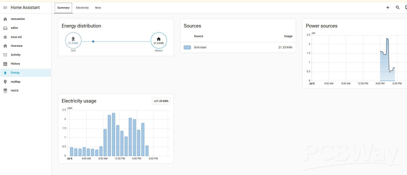
Energy dashboard in HA
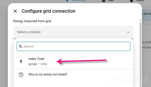
Your Linky being recognized you can add it to your energy dashboard :
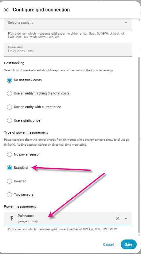
On the same page at the bottom you can add the power source (for real time monitoring)
And if you go back to the energy dashboard you will get this :
Finally your linky device can be used into other dashboards :
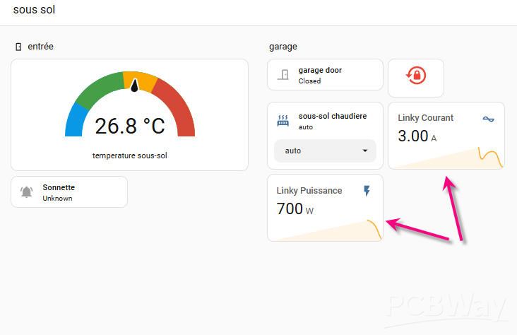
here is my "underground dashboard" ! I have now access to the current and the provided power !