 dfyR433

1. Power Supply & Gate Drive Regulation
To prevent high-voltage supply fluctuations from damaging the switching MOSFET gates:
- An LM7812 linear regulator steps down the input voltage to a stable 12v rail dedicated to gate-drive biasing.
- Heavy decoupling capacitor filtering 2200uf bulk electrolytic paired with ceramic bypass capacitors) stabilizes the bias rail against switching transients.
- Gate protection is reinforced using 12v Zener diodes (D_4, D_5) to clamp gate-to-source voltage gs spikes.
2. ZVS Resonant Tank
The oscillator uses a classic Royer topology optimized for high efficiency:
- Fast Recovery Feedback: Ultra-fast recovery diodes (MUR120) cross-couple the gates to the opposing drains, ensuring MOSFETs switch exactly at the zero-voltage crossing point to virtually eliminate switching losses.
- LC Tank System: Two 100uh high-current toroidal inductors decouple the DC supply from the AC resonant tank, maintaining continuous current conduction.
3. Analog Audio Modulation Stage
Unlike standard ZVS drivers that run at fixed duty cycles, this board integrates a dedicated modulation channel:
- Signal Conditioning: Audio input is AC-coupled via C_16 10uf to remove DC offsets and passed through a current-limiting resistor.
- Pre-Amplification: A complementary push-pull BJT driver stage (Q_4 / Q_5) amplifies the low-level audio signal to cleanly drive the high gate charge Q_g of the modulator MOSFET Q_1.
- Modulation Control: The modulator MOSFET Q_1 acts as a series pass element or active interrupter, translating incoming audio frequencies into amplitude-modulated current variation in the output load.
4. PCB Layout & Thermal Management Strategy
- High-Current Path Optimization: Designed with wide, heavy-copper traces and terminal blocks to minimize trace resistance and inductive loop areas.
- Passive Cooling: Positioned dual massive star-profile heatsinks mid-board to isolate the high-temperature power switching elements from the sensitive analog audio input circuitry.
- Capacitor Array Spacing: Evenly gridded film capacitor bank allows air circulation to prevent hot spots during prolonged resonant operations.
- Signal Isolation: The sensitive 3.5 audio jack and pre-amp BJTs are physically clustered at the lower right of the board, far from the high-frequency electromagnetic interference (EMI) of the resonant LC tank.
5. Tools & Technologies Used
- EDA Tool: KiCad / Altium Designer (for schematic capture, 3D modeling, and PCB layout).
- Components: IRFP460 MOSFETs, LM7812 Regulator, MUR120 Fast Diodes, Metalized Polyester Film Capacitors.
- Skills Demonstrated: Mixed-signal PCB design, thermal management, high-power routing, resonant power converters, and analog audio design.
 Sagar 001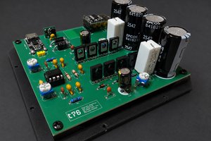
 Marco Tabini
 cris
cris
 Brian Cornell