 agp.cooper
Designing The Body
-
I have started designing the body. First thoughts is a bumper bar:
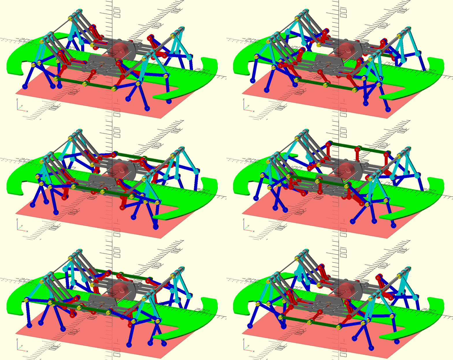
It serves several functions:
- A floor to the battery and micro-controller board.
- Protection for the legs (they look rather fragile).
- A sensor platform.
- A structure to increase rigdity.
I think I will need to extent the motor plate forward and aft, to reinforce the bumper bar floor.
-
I have selected 2 mm thick PTFE M3 washers.
Bought the rods and pins.
Bought the Nema 14 round steppers.
A couple for the motor shaft (5 mm) to the drive shaft (3 mm).
-
I looked at buying M3 collars but after a long consideration, stayed with gluing the "fixed" rods/collar to the shafts.
-
While there are commercially available stepper drivers, a long long time ago I built discrete drivers based on TTL logic:
 I seem to remember that I added protection diodes between ground and the output, and the output to the power supply.
The input transistor was not used but looks like a good idea.
-
For the micro-processor I feel rather retro. As in the vein of "How to build your own working robot pet." by Frank DaCosta. A book I repurchased after more than 40 years. So I am looking at the Intel 8085.
-
When I look at the bumper bar, I could add a nose and it would look like a dog from above!
That is the bumper bar looks like a head and a set of ears, all it needs is a snout and a nose,
-
I started this project on the 28th of June so tomorrow is one month.
-
Its been a few days with some success and failures to report:
- Good progress on refactoring the code, getting slot and tab working:
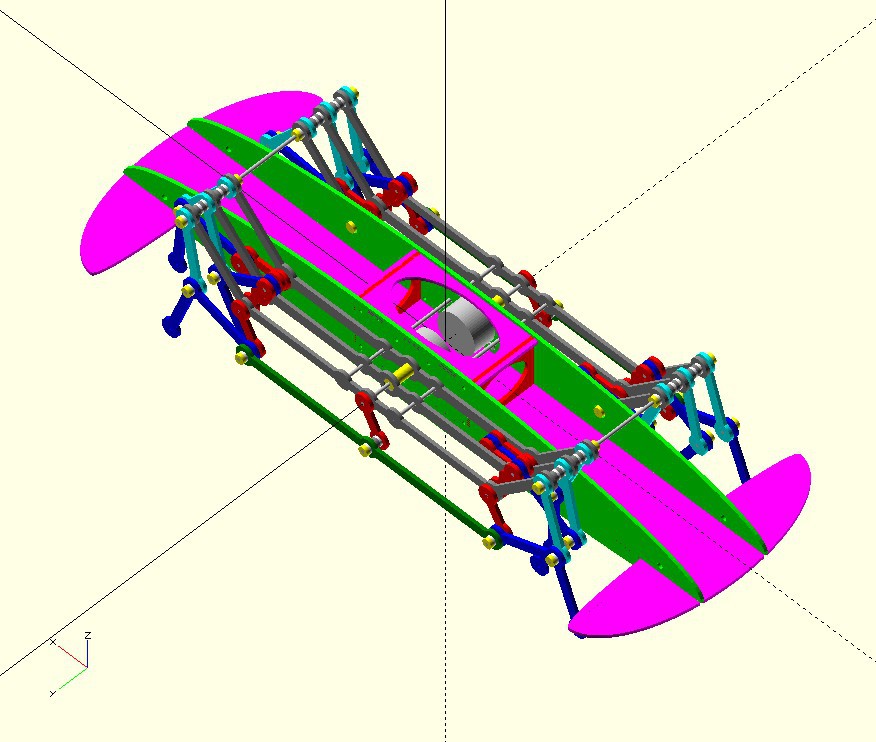
If you wondering, the big holes in the carriage torsion box, are used to get access to the stepper motors.
-
Balancing the Rotating Mechanisms
I looked at a balancing the crank:
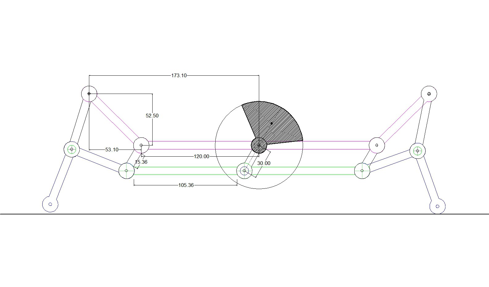
The double thickness counter balance matches weight and centre of mass so should work okay.
-
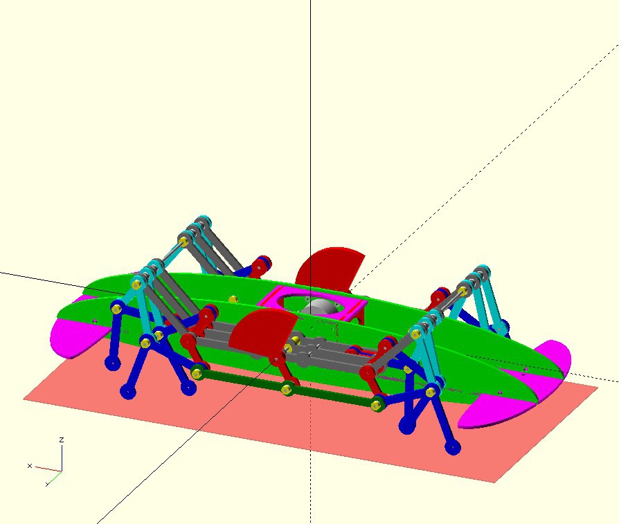
Here is my first pass counter balance design:
-
Recalculated the counter balance weight (as best I could):
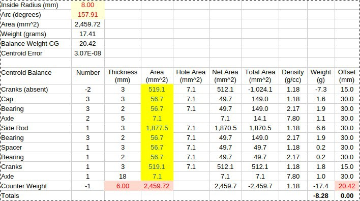
Made the counter weight balance small as practical, but no allowance for reciprocating parts.
Usually an allowance of 50% to 90% of the moment of these parts is made (for internal combustion engines).
-
Bugs in OpenSCAD
Bug in OpenSCAD are silent (but Syntax errors are noisy).
-
To implement Slot and Tabs, I wrote Function Slots(). Easy enough, create some slots, translate them to the edge in question and take the difference:
    // Add Slots for Bulkhead
    mirrorCopy([1,0,0])
    translate([cgap/2-5,0,0])
    rotate([0,0,90])
    slots(wgap,plateThick,3);
-
Worked fine until it does not!
Spent a day working through this, the answer was a vertical version of slots to avoid the rotation:
-
Slotting
The slotting code work with odd and even matching slots or tabs:
// Make Slots for edge joins
module xslots(l,d,n) {
  let(m=n%2)
  let(w=l/(2*n+2*m-1))
  for(i=[1-n:2:n-1+0.001])
  translate([i*w,0,0])
  cube([w+0.01,d+0.02,3*d],center=true);
}

module yslots(l,d,n) {
  let(m=n%2)
  let(w=l/(2*n+2*m-1))
  for(j=[1-n:2:n-1+0.001])
  translate([0,j*w,0])
  cube([d+0.02,w+0.01,3*d],center=true);
}
-
For example, adding slots and tabs using tab = 3 and slots = 4, to bulkheads:
  // Add Bulkheads
  color("Red") mirrorCopy([1,0,0]) {
    translate([cgap/2-5,0,0])
    rotate([0,90,0])
    difference() {
      cube([wgap,mgap,plateThick],center=true);

      // Add Tabs on Sides
      mirrorCopy([1,0,0])
      translate([wgap/2-plateThick/2,0,0])
      yslots(mgap,plateThick,4); // 4 slots and 3 Tabs

      // Add Tabs on Top and Bottom
      mirrorCopy([0,1,0])
      translate([0,mgap/2-plateThick/2,0])
      xslots(wgap,plateThick,4); // 4 slots 3 and Tabs
    }
  }
-
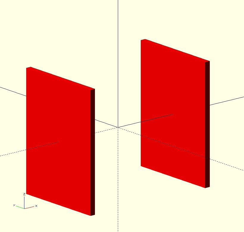
First the bulkheads with edges oversized:
-
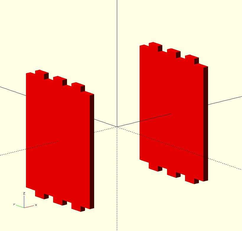
First set of slots cutout:
-
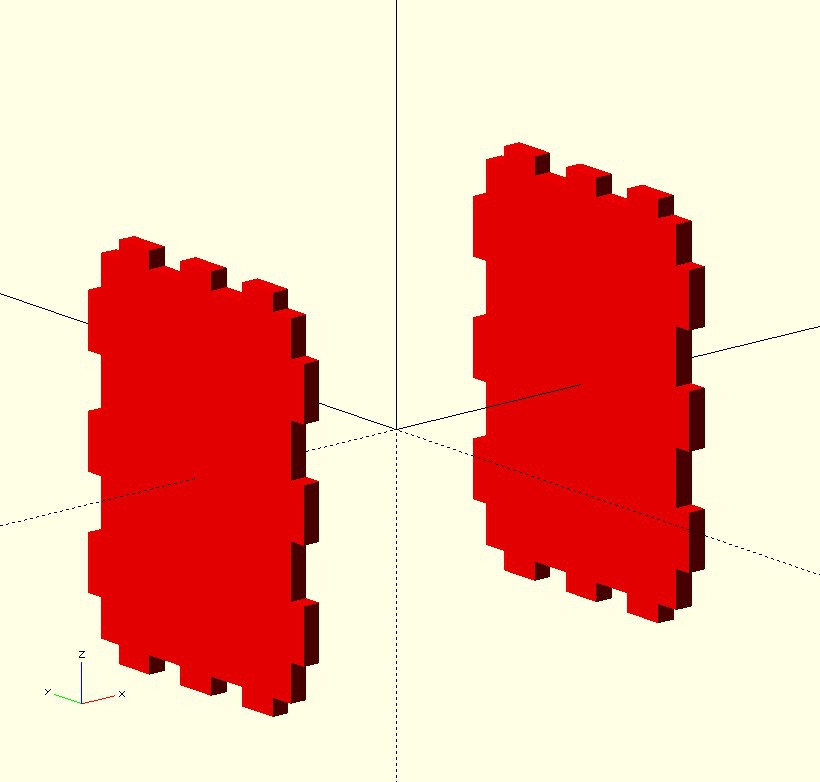
Second set of cutouts:
-
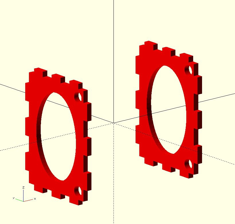
Other cutouts:
-
So the trick here was to use n=3 for tabs and n=4 for slots, keeping d=depth and l=length the same.
Note: (1,2) and (3,4) and (5,6) etc, are matching sets.
Now some matching slots in the Top:
  color("Magenta") translate([0,mgap/2-plateThick/2,0])
  rotate([90,0,0])
  difference() {
    cube([cgap,wgap,plateThick],center=true);

    // Add Tabs to Vertical Support
    mirrorCopy([0,1,0])
    translate([0,wgap/2-plateThick/2,0])
    xslots(cgap,plateThick,4);

    // Add Slots for Bulkhead
    mirrorCopy([1,0,0])
    translate([cgap/2-5,0,0])
    rotate([0,0,90])
    xslots(wgap,plateThick,3);

    // Add Top Cutout
    scale([(cgap/2-3.5-3*plateThick)/(wgap/2-3*plateThick),1,1])
    cylinder(h=3*plateThick,r=wgap/2-3*plateThick,center=true);
  }
-
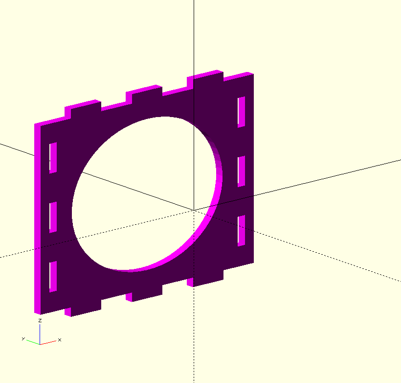
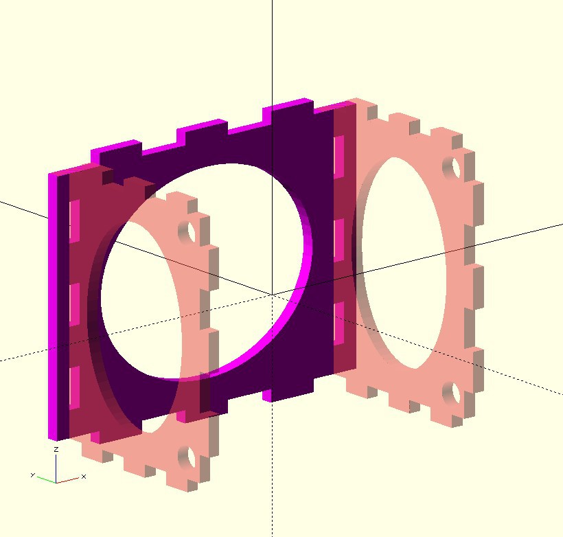
And finally, assembled and checked for fit:
-
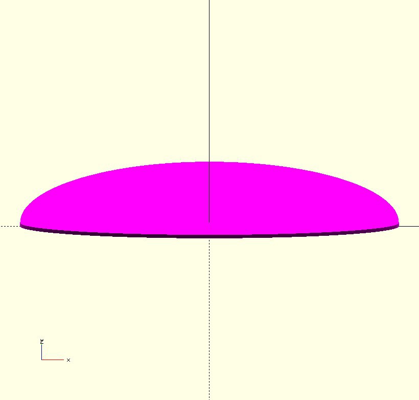
The Elliptical Wing Function
The method for mathematical shapes is two step, first the function:
// Bumpers
function ellipticalWing(a,b,c) =
  [for(e=[0:3:360])
    if (e<180) [a*cos(e),b*sin(e)] else [a*cos(e),c*sin(e)]
  ];
then the polygon/extrusion:
   // Make an Elliptical Wing (Bumper)
    linear_extrude(height=plateThick,center=false)
    polygon(ellipticalWing(wgap/2+4*sgap,50,10));
-
The Bumper (an elliptical wing):
-
AlanX
Discussions
Become a Hackaday.io Member
Create an account to leave a comment. Already have an account? Log In.