 Daniel

First I tried sending the video as plain digital data (ones and zeros). But the math kills it. One basic 640×480 black-and-white frame is about 300 kB. A simple homemade laser link can maybe switch around 1 Mbit per second, which works out to less than one frame every two seconds. To get smooth video that way I'd have to shrink the picture to something like 32×32 pixels, which is useless.
Then I tried turning still pictures into sound and sending that. It works, but one picture takes somewhere between 8 seconds and 2 minutes, so it's nowhere near real time.
What finally worked was going back to old analog TV video (composite video, the yellow RCA cable). The whole picture — brightness, colour, and the timing pulses — is already packed into one wire as a single wave about 5 MHz wide. So instead of flashing the laser on and off for each bit, I just make the laser brighter and dimmer to follow that wave. That's enough for smooth 50–60 frames per second.
How the signal gets across
1. A camera plugged into a Raspberry Pi. The Pi's TV-out turns the picture into a composite video wave and sends it out the yellow RCA jack. (For early testing I used an ESP32 that just makes a test pattern.)
2. That wave goes into my transmitter circuit, which uses it to control the laser's brightness.
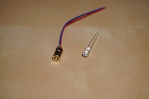
3. The laser shoots across a gap to a photodiode on the other side.
4. My receiver circuit turns the light back into the video wave.
5. That goes into a USB capture card so I can see the picture on a laptop.
The transmitter
You can't just wire the laser straight to the video output. The video signal is only about 1 volt and can't supply much current, but the laser needs a couple of volts just to turn on, plus around 20–30 mA to run. So the circuit does two jobs:
- A 10k potentiometer sets a steady voltage that keeps the laser glowing at medium brightness. This is the middle level the picture rides on top of.
- The video signal is added on top through two capacitors in parallel — a big 47µF one for the slow parts and a small 100nF one for the fast parts.
- A 2N2222 transistor (wired as an emitter follower) takes that small mixed signal and gives it enough current to actually drive the laser, without loading down the Pi.
The receiver
On the other side I needed something fast enough to follow a 5 MHz signal. A solar panel is way too slow, so I used a BPW34 photodiode, and I run it in reverse bias to make it even faster. The photodiode only makes a tiny current, so I turn that into a real voltage with an op-amp wired as a transimpedance amplifier.
I used an LM318N op-amp because it's fast — normal audio op-amps are too slow and smear the picture. The important parts are in the feedback: a 2.2k resistor sets how big the output is, and a small 8.2pF capacitor stops the amplifier from ringing. The whole thing runs off two 9V batteries so the signal can swing both above and below zero.
The annoying part: getting it into the capture card
Plugged straight into a TV it looked great. But into a cheap EasyCap USB capture card the picture smeared sideways and tore diagonally. Two fixes solved it:
- The smearing was reflections bouncing back in the cable. Adding one 75 ohm resistor in series at the output soaked those up and made the edges sharp again.
- The tearing was because my signal was a bit too strong for the capture card's sync detector. I fixed it by slowly turning the transmitter potentiometer down until the picture locked and held steady.
Of course, figuring out exactly what was wrong with a 5 MHz analog signal is basically impossible if you can't actually see the waveform. Huge thanks to PCBWay for the sponsorship and sending over this oscilloscope. While you might know them for manufacturing circuit boards, they also support creators and sell a ton of maker hardware, tools, and test gear in their store. pcbway
 Nathan Kerns
 Ero
Ero
 Julien
 Sky Carter