Kyle Mayer

Why this imager
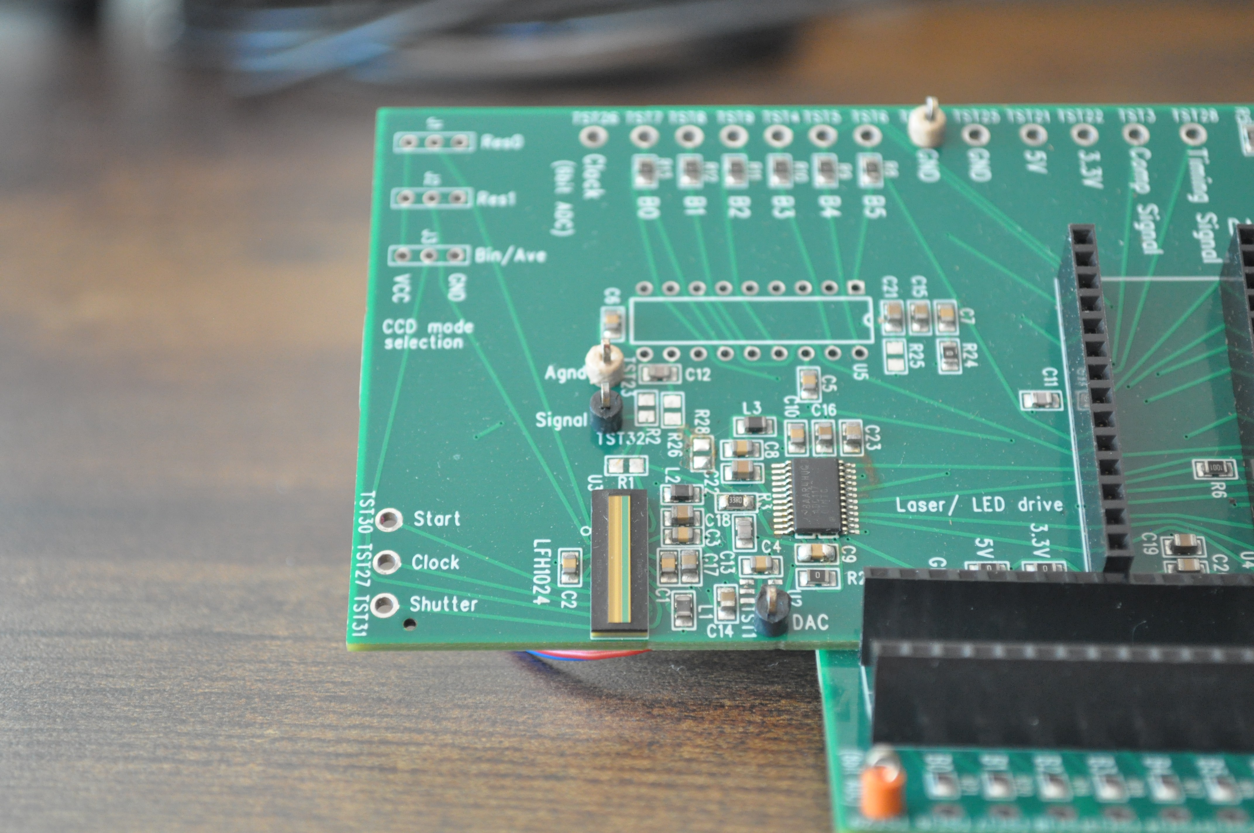
The LFH1024's pixels are 12.7 µm wide and 600 µm tall, a 50:1 aspect ratio. This allows enough light gathering that a lens-less slot aperture works at full speed. It also supports a 5 MHz pixel clock, which works out to about 4,800 full-resolution scans per second, or around 18,000 using the sensor's on-chip binning. It costs $20–35 and comes in a ceramic BGA coarse enough to hand-solder.
I also built prototypes with an Espros EPC901, but it's a bare silicon die with a tight-pitch BGA, and assembly was a nightmare.
Reading it out
My original firmware bit-banged the readout with interrupts turned off to control the critical timing of the multiple interleaved clocks (pixel clock, ADC clock), synced to digital reads. It works, but the CPU can do nothing else while a scan runs. The final firmware moves the whole job into hardware: the Teensy's FlexPWM generates the pixel clocks, a compare event triggers an eDMA capture, and the completion interrupt runs the centroid math. The three sensor heads share the clocks, so all 24 ADC bits arrive on two GPIO ports and get captured together. The phase between the ADC clock and the capture instant is tunable at runtime; at 5 MHz there are only tens of nanoseconds of timing margin per pixel. I kept the bit-banged version in the firmware for comparison.
Finding the spot
Each scan is a row of 8-bit samples with a bump in it somewhere. The pipeline: subtract a dark frame, find the peak, then take an intensity-weighted center of gravity over the half-max window.
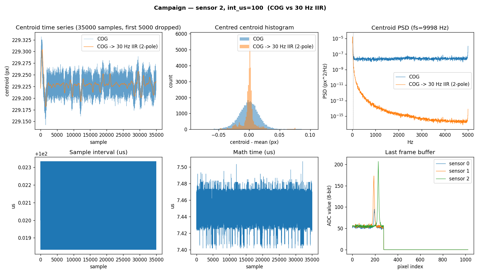
The noise figures come from 40,000-scan campaigns on real hardware.
The prototypes
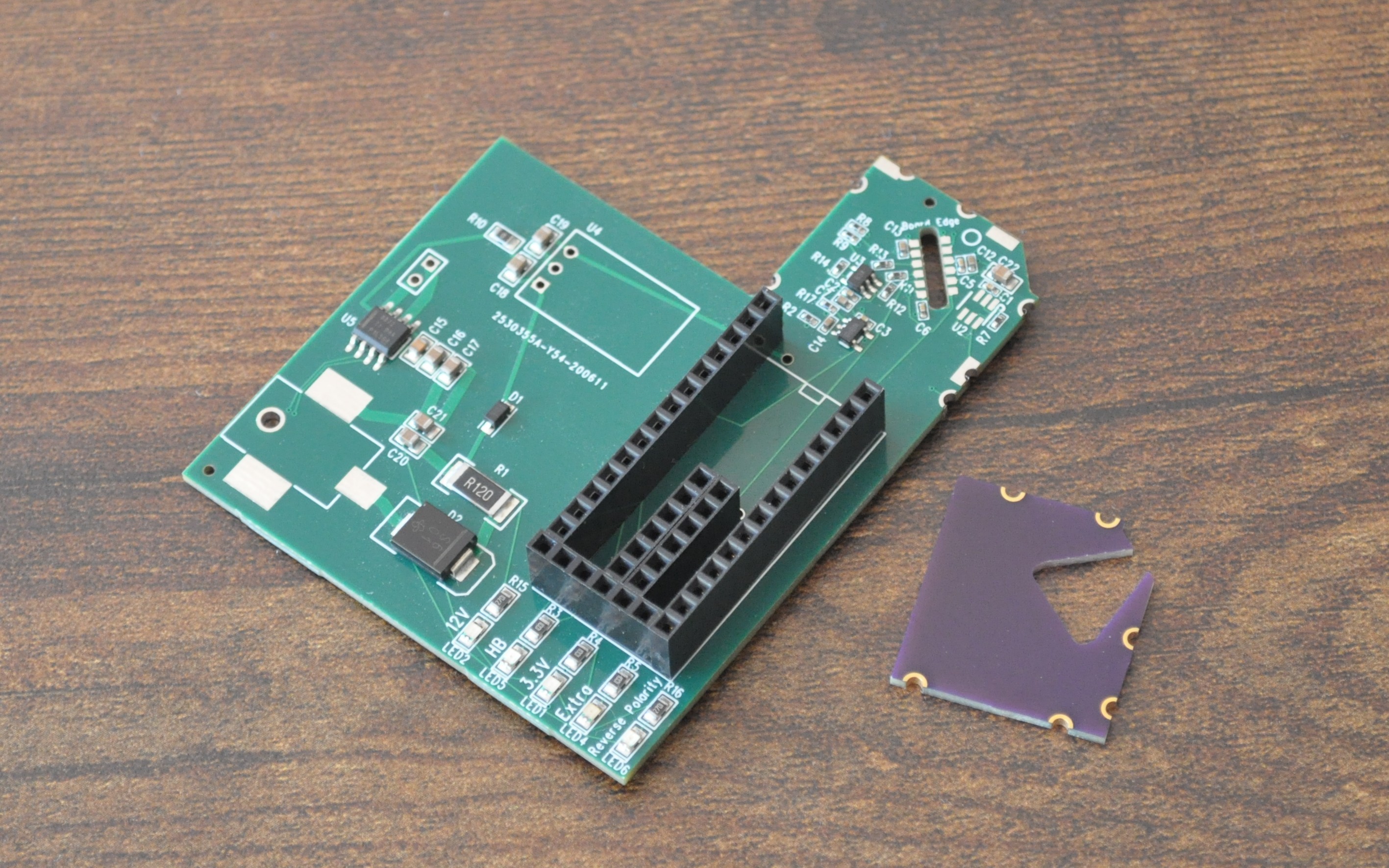
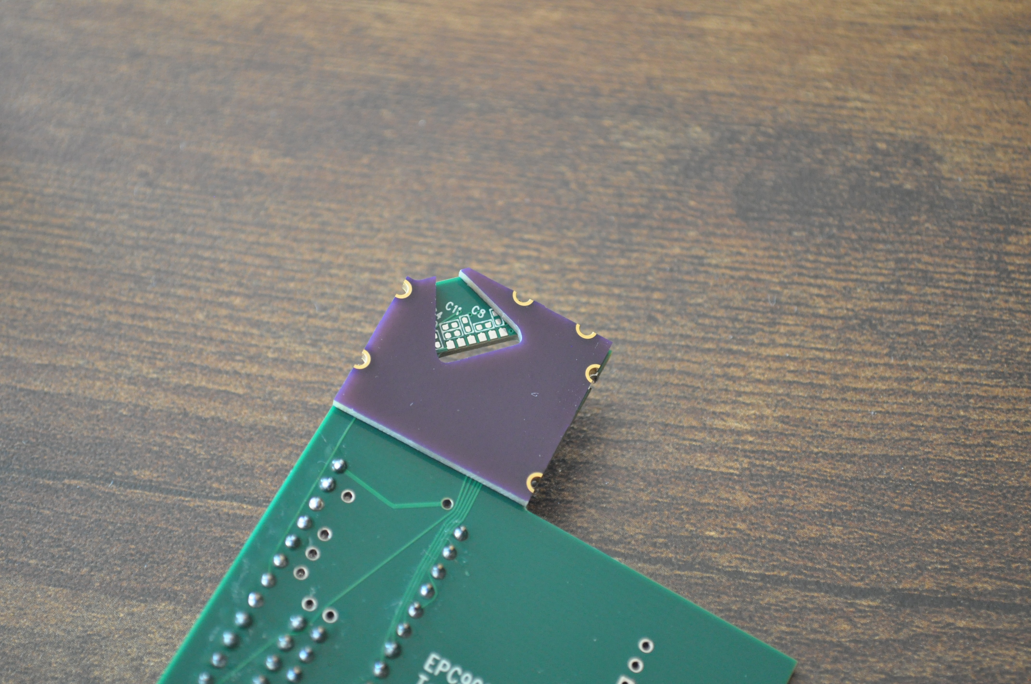
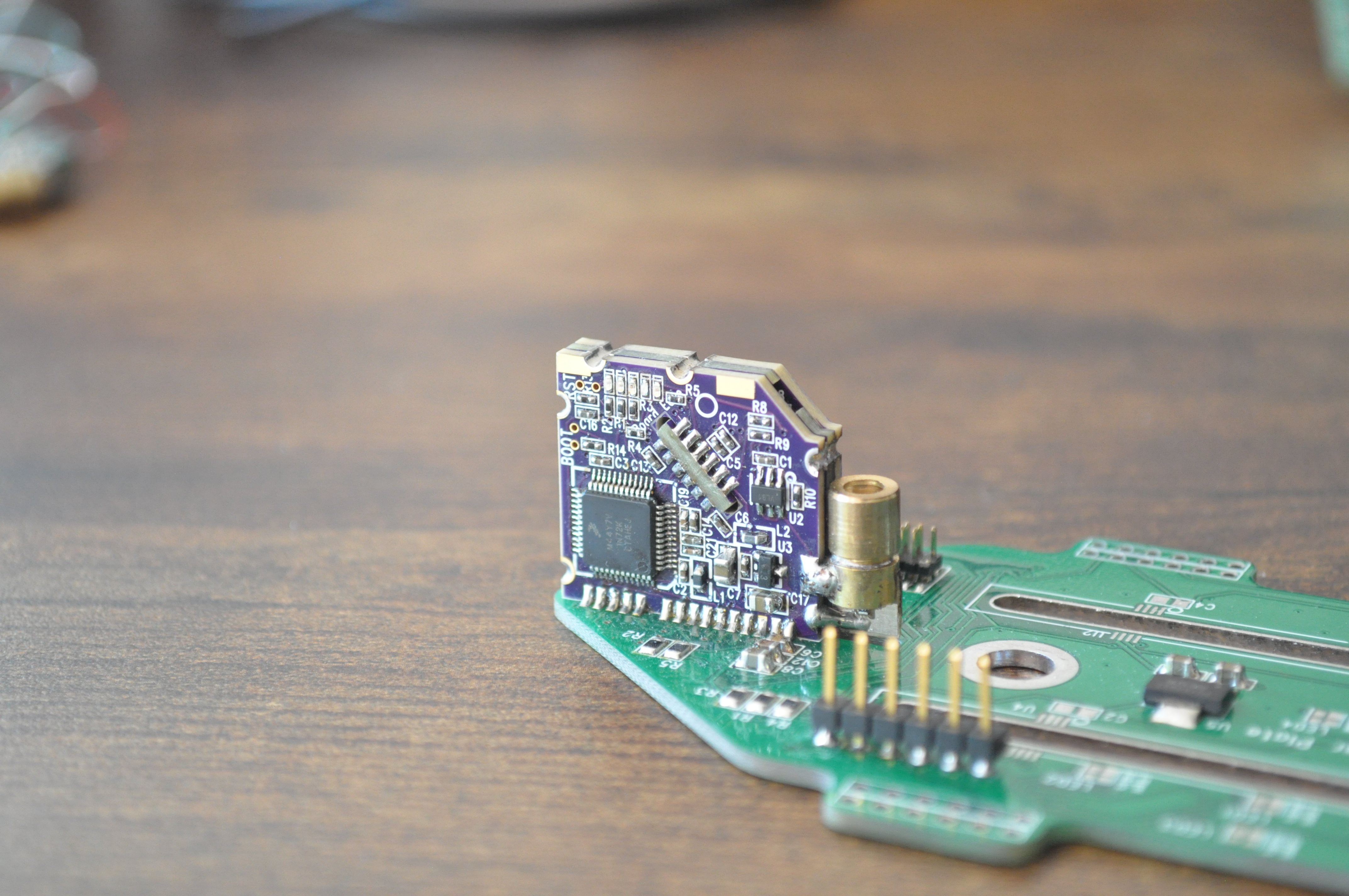
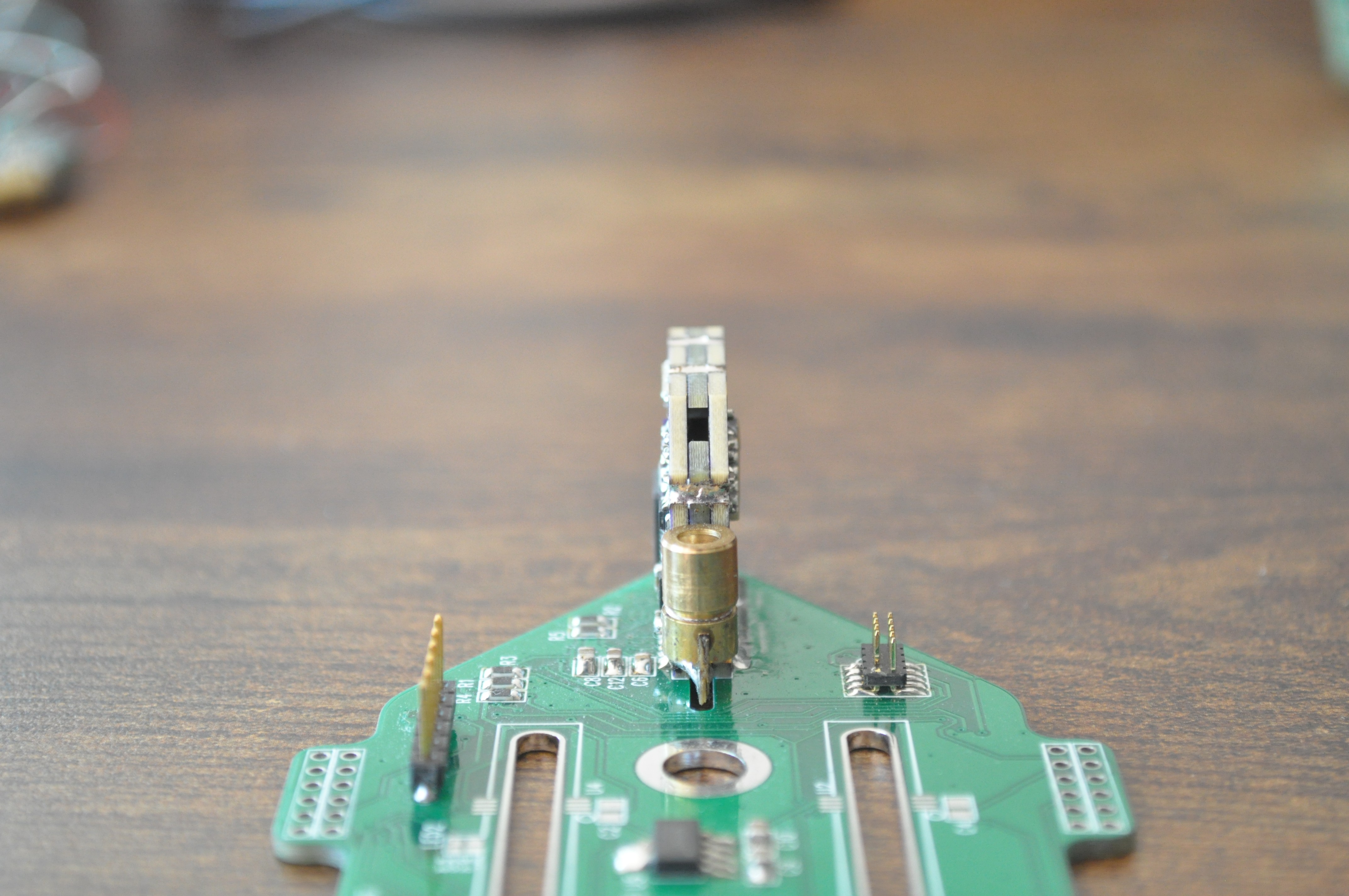
There are five generations between cardstock and the three-sensor rig in the photos. The middle revisions carried an EPC901 and a Kinetis microcontroller with fast internal ADCs.
Specs at a glance
Range: 0–10 mm, mapped onto a sub-section of the array
Noise: ~0.02 px RMS on-sensor (≈0.25 µm of spot position)
Scan rate: ~4,800/s full resolution, ~18,000/s binned (5 MHz pixel clock)
Imager: iC-Haus LFH1024, 1,024 px, 12.7 × 600 µm pixels
Emitter: 5 mW-class red laser diode
Digitizer: ADC1173 8-bit parallel, one per head, three heads per Teensy 4
Cost: under $50 per sensor head; under $200 for the 3-sensor assembly shown in the photos
Host link: USB serial, with a live viewer (PySide6) and NPZ recorder
Honest limitations
This is not an industrial head. A real lens gathers far more light than my slot aperture, which buys range and speed I don't have. Absolute accuracy depends on the laser-to-imager angle staying constant, and a few microns of thermal expansion across the PCBs would plausibly shift the calibration. I haven't even tried to measured that. In my setup, the laser diode is soldered directly to the board to keep the geometry as rigid as I can make it. The result is low noise, not necessarily low absolute error.
For context: $10 Sharp GP2Y modules use the same triangulation principle (with a lens and a position-sensitive detector instead of an imager) at ~26 Hz and centimeter accuracy; a ~$326 Panasonic HG-C1030 gives 10 µm repeatability below a kilohertz; and the sub-micron, multi-kilohertz heads from Keyence and Micro-Epsilon are quote-only.
GUI
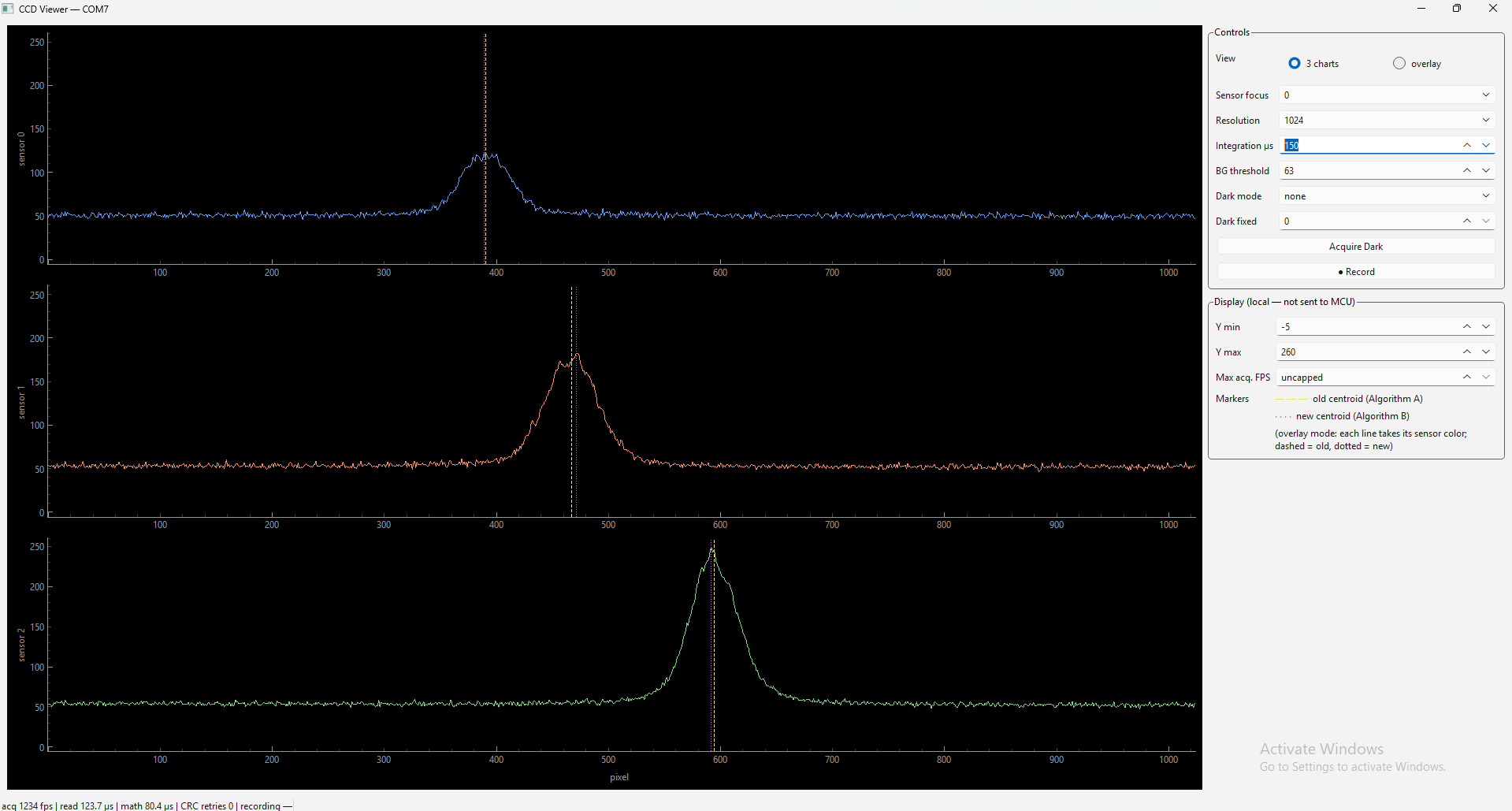
There's a PC-side Python program included in the repo for viewing the raw sensor data and collecting runs.
Files
Firmware (Teensy 4, Arduino), the PC viewer, and Gerbers: https://github.com/promnius/LaserTriangulationRangefinder
Bonus Photos