Mr.50mm
An adapter to allow Phase One 645 mount digital backs of film backs to fit on the Mamiya Press Universal.
For The Main plate, there are 2 uploaded, the original 4.8mm thickness, this was made in the event my measurement or print wasn't exactly correct and sets the digital back about 0.5mm closer into the camera body then expected for the film plane. There is a 5.3mm thickness one included, if your printer is well calibrated this should exactly put the back where the film plane is expected, if you can't seem to achieve infinity focus with it print the 4.8mm and adjust the RF as per the instructions below.
Either way you may still need to adjust it a tad anyways but at the least the 4.8mm will ensure infinity focus is possible.
If you'd like to see my video discussing the adapter have a look here,
Or if you want to check out the channel in general look here,
https://www.youtube.com/channel/UCirQEIw2y461w9w8tJNEM3Q
Additionally I have now updated this to include parts to make the Super 23 Adapter.
That video can be found here: https://youtu.be/HpiyEBusfTg
This adapter is a bit different, it clips on to the back of the Mamiya M mount, as such it extends behind it and above to make space to clear the digital back. This means the sensor is way behind the normal film plane. However infinity focus can still be achieved but only using collapsible lenses, they lower to facilitate the tilting mechanism but in this case we are going to use it to Super 23. Additionally the files for the Super 23 are labelled as such, NONE of the other files are part of that adapter. There is a template for the metal hooks, these one require the user to bend them sharply at 90 degrees, again the template for the other adapters will not apply, so don't use those as a template.
Things you’ll need the following things to do this project:
3D printer that can print as big as 130mm by 110mm by 6mm. Not overly big. Dremel with the cutting disk. 1mm sheet steel that's at least 12mm by 52mm 4 M2 screws at 10mm/8mm with nuts (not required for Super 23) 2 M2 screws at 15mm (4 M2 at 5mm (With 2 nuts), it will be used to secure the metal hooks to the print and must be short enough to not interfere with the mount to the Super 23 M film mount, 2 will also be used to secure the lower lip, for this print I didn't integrate that into the main body so it must be affixed)
A roll of black tape that's thin and supple, recommend the bicycle handlebar finishing tape, it’s cheap and easy to work with.
Print Settings
- Printer brand:
Creality
- Printer:
Ender-3 V2 Neo
- Rafts:Yes
- Supports:Yes
- Resolution:
200um
- Infill:
50%
- Filament material:
PLA
- Filament brand:
Unknown
- Filament color:
Black
- Notes:
I personally used I believe 6-8 walls for the prints I'm sure lower numbers would work but just to minimize the chance of the adapter breaking I went thick.
I also oriented the main plate vertically standing up. It does mean you need more support and the support for the metal clips is hard to remove but I find on my printer the print comes out flatter.
If your printer supports it and you want to print vertically I would suggest tree style support to make this easier to remove.
Printing it flat should be fine if your machine produces prints that don't have much warp to them.
Fabrication of Metal Clips
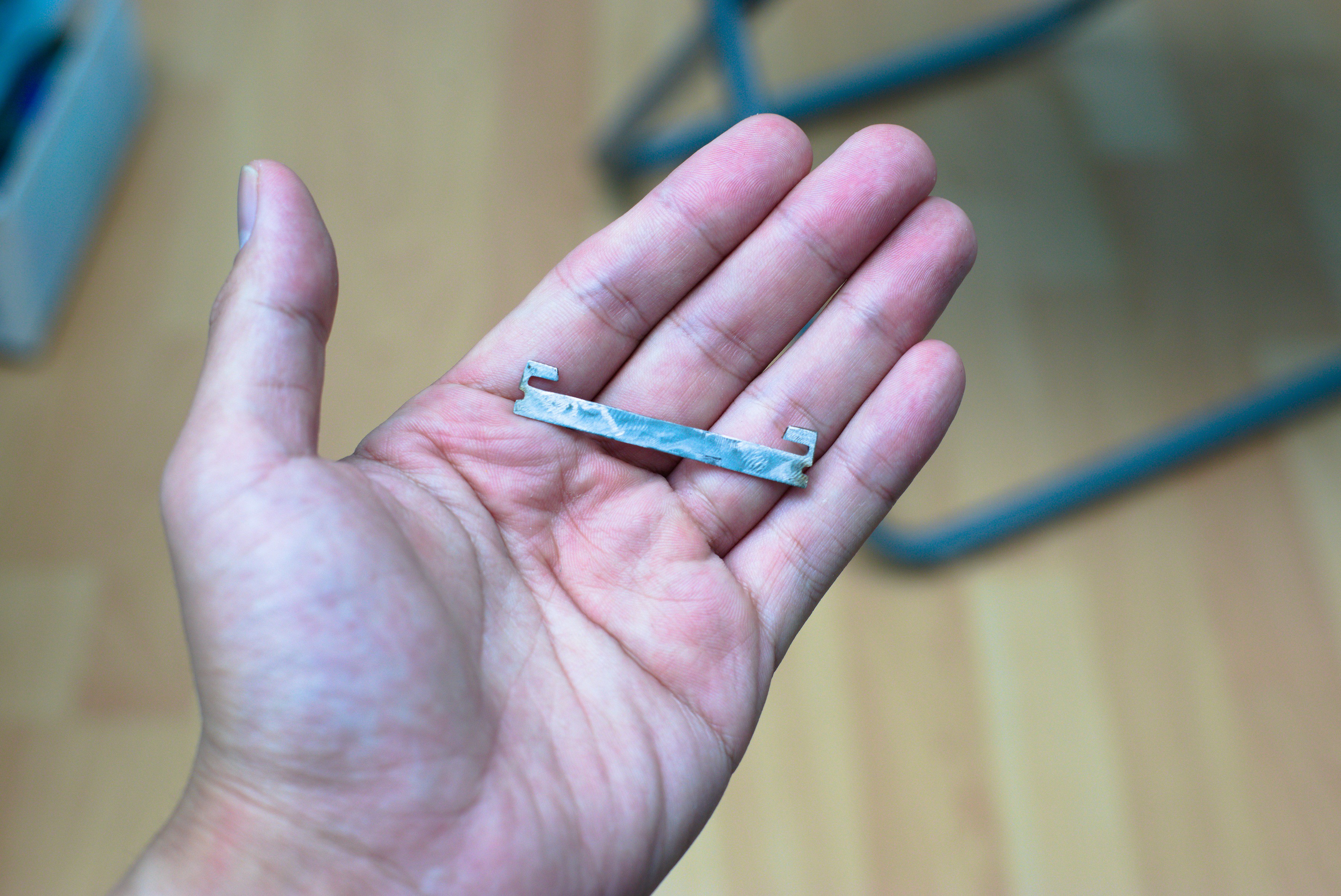
*** Before you begin, this requires a bit of metal working, cutting some thin 1mm sheet metal with a Dremel and an appropriate cutting disk, if you are uncomfortable with that, consider asking for help to fabricate.
ADDITIONALLY DO NOT USE THE 3D Printed Template provided as the clip, it is too weak and could result in a dropped digital back.
When working with Metal fabrication the workpiece WILL get hot and there will be metal shavings flying about, USE PPE, thick gloves and goggles are a minimum. Plus whatever other safety is recommended with whatever tool you are using to cut the piece.
Ensure you have a sheet metal that is at least 12mm by 52mm more is recommended to give you a spot to hold onto.
When fabricating make sure the notches in the side are as close to the template as possible, these are where M2 screws will slot between to hold the clips in and thus the back on.
When testing the clips, do so on a level platform with the back supported, and test it before and after you install the clip onto the print, ensure the back locks in! Gravity is not our friend.
Assembling The Parts
This is essentially 3 3D printed parts and 1 metal fabrication.
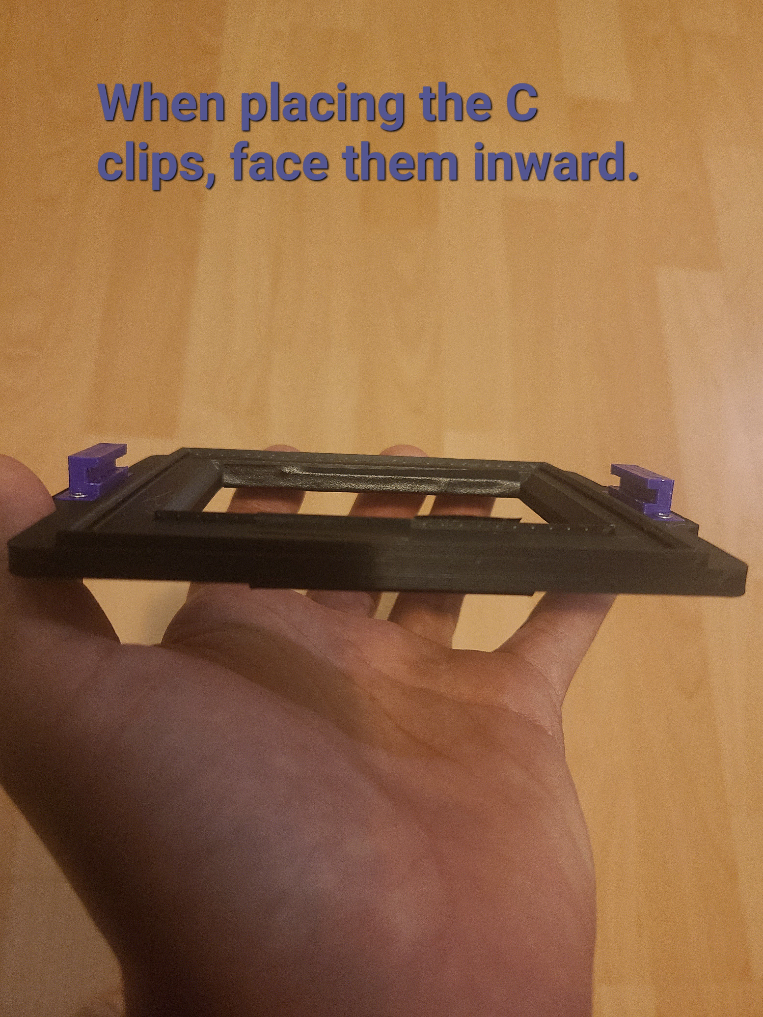
The 3D printed parts can be affixed using 4 M2x10mm screws and nuts, the channels in the smaller prints are to be facing inward to allow for the back to lock into the camera.
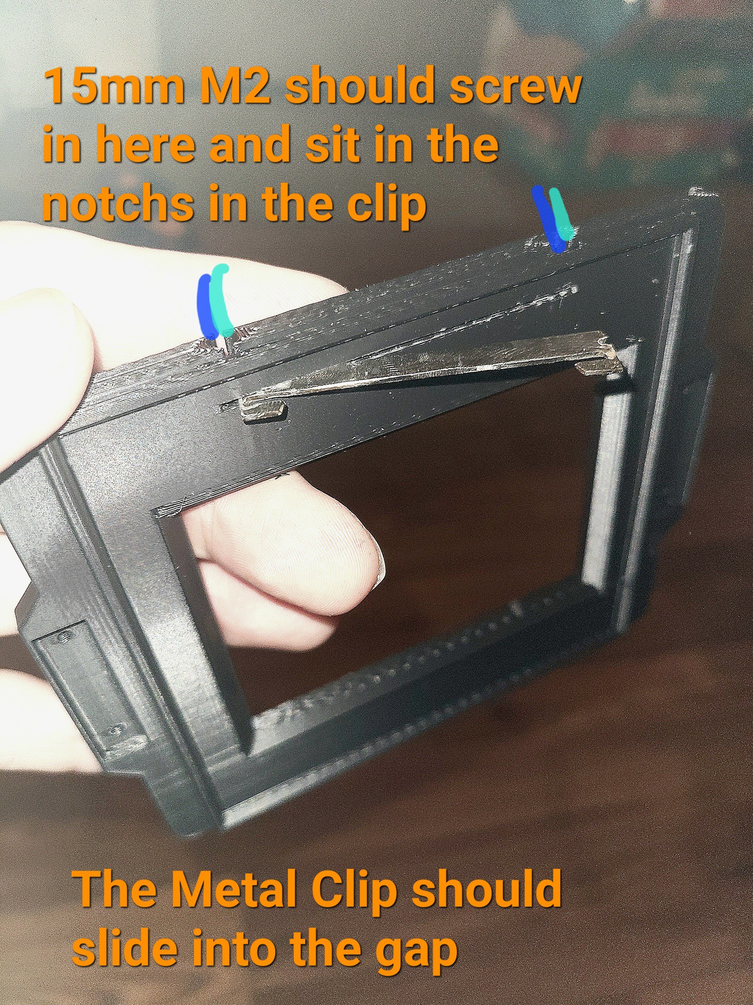
The Metal digital back clip slides into the gap in the middle of the print, once in screw in longer M2x15mm screws slowly through the print and the clips, make sure the screw actually sits between the notches, and doesn't just press into the plate as it'll likely cause you to strip the screw or the PLA hole, providing poor fixation. There is no hexnut used to fix the screw as I just treated the screw like a self tapper and just screwed it directly into the PLA slowly.
A new STL has been uploaded, it's the C-Clip for the Polaroid 600SE, I just modified the clips on the Press Universal and tested the fit on my 600SE, it does appear to work!
Light Sealing
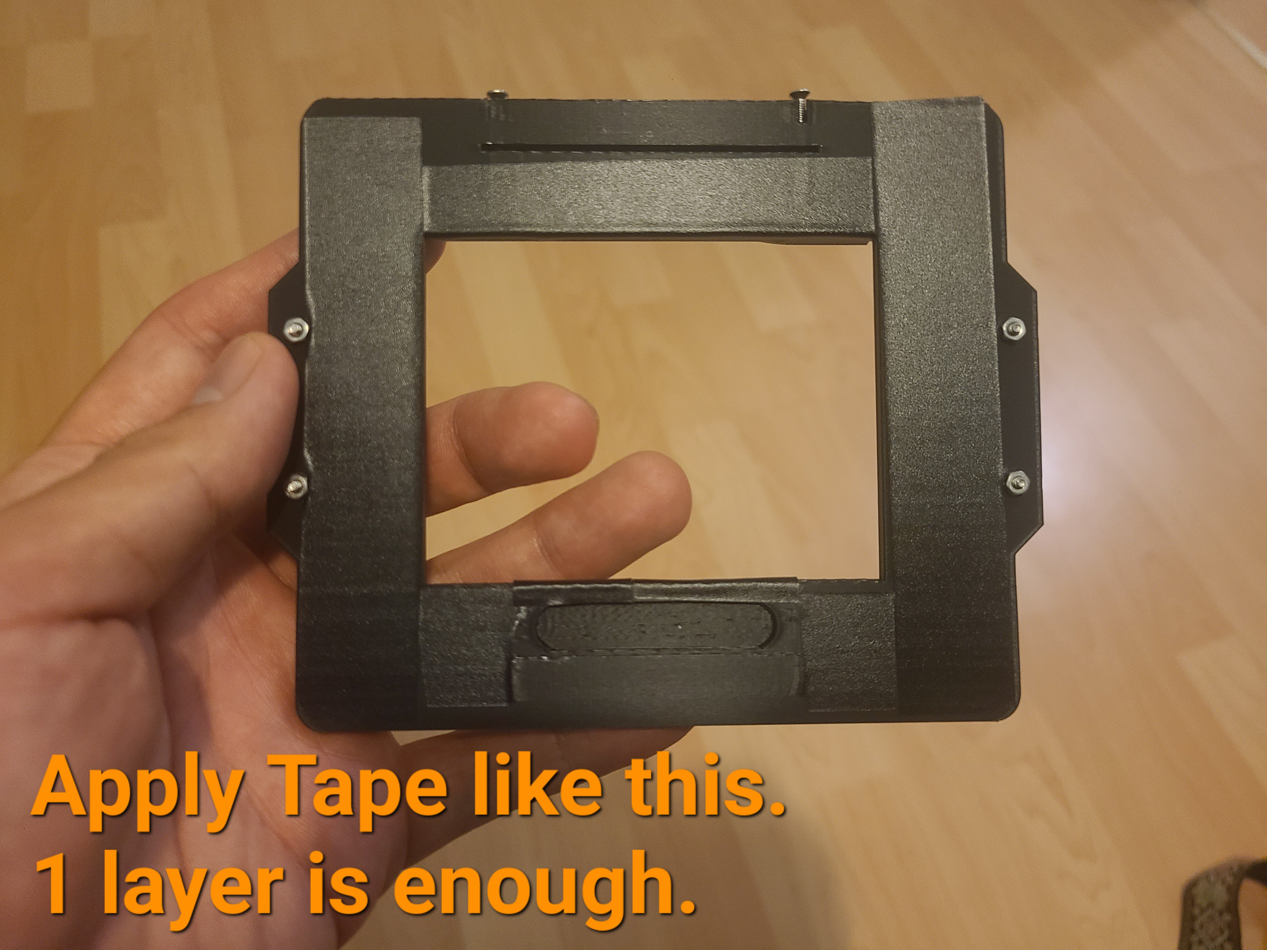
Last step requries use of some thin but supple tape, I used Black bicycle handlebar finish tape, but electrical tape should work, apply a thing layer to the side where the back will sit, this should be enough to seal the back to the adapter. If the back appears loose try a second layer.
Adjusting the RF
Now this back isn't perfect, it's not likely exactly going to be inline with the film plane of the camera, luckily I designed it to at least retain infinity focus (the back is a bit closer than expected to the camera). So you'll need to calibrate the rangefinder, this is not difficult, especially with a digital back, set the camera to infinity and then take a photo.
Take note, of where the lens is focused and review the image, it's likely not in focus, move the lens a bit and take another photo, review it until it's in focus.
You'll notice how far off the Rangefinder is to actual infinity, now adjust the finder so that the image aligns where your actual indicated infinity is. Keep in mind adjusting the screw will apply pressure to the RF so double check the rangefinder window.
Another youtuber has posted a guide to the adjustment! Have a look here.
https://www.youtube.com/watch?v=AHJOG26SVuA