Close
0%
0%

2 Inverters + 2 PFC Circuits Explained

These projects are suitable for electronics enthusiasts who want to learn about inverter technology, switch-mode power supplies, and high-po

Public Chat
Similar projects worth following
0 followers
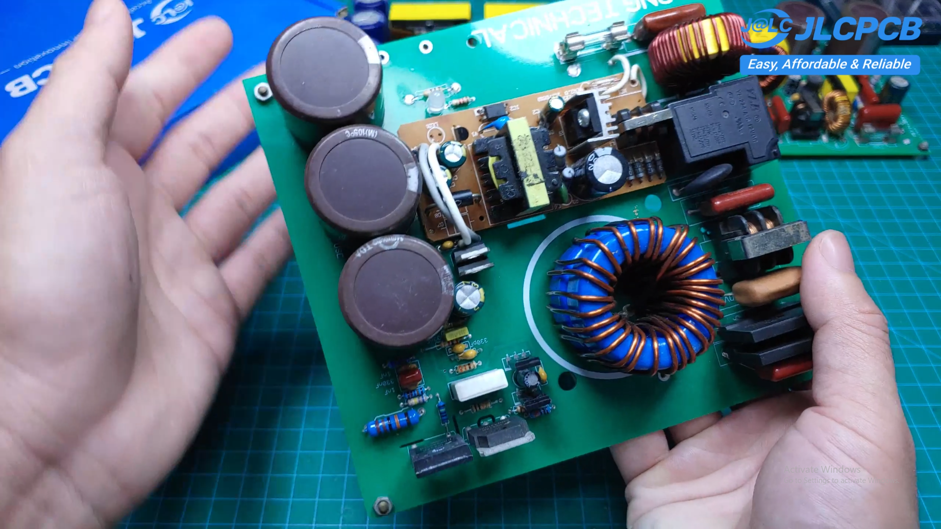
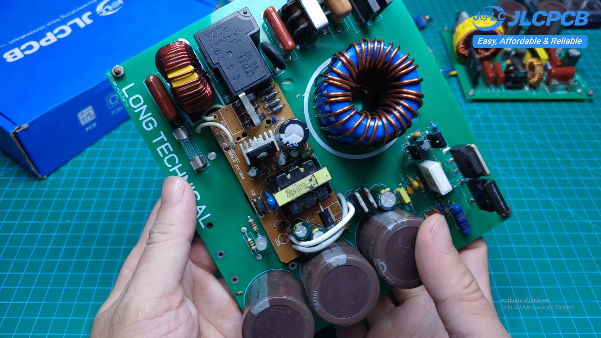
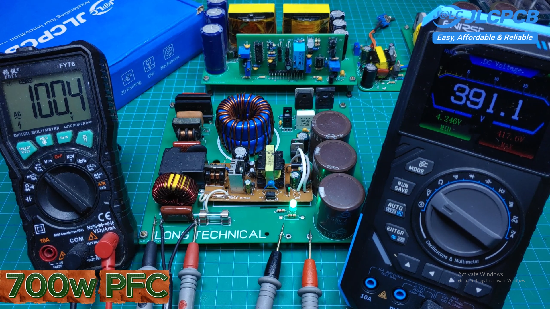
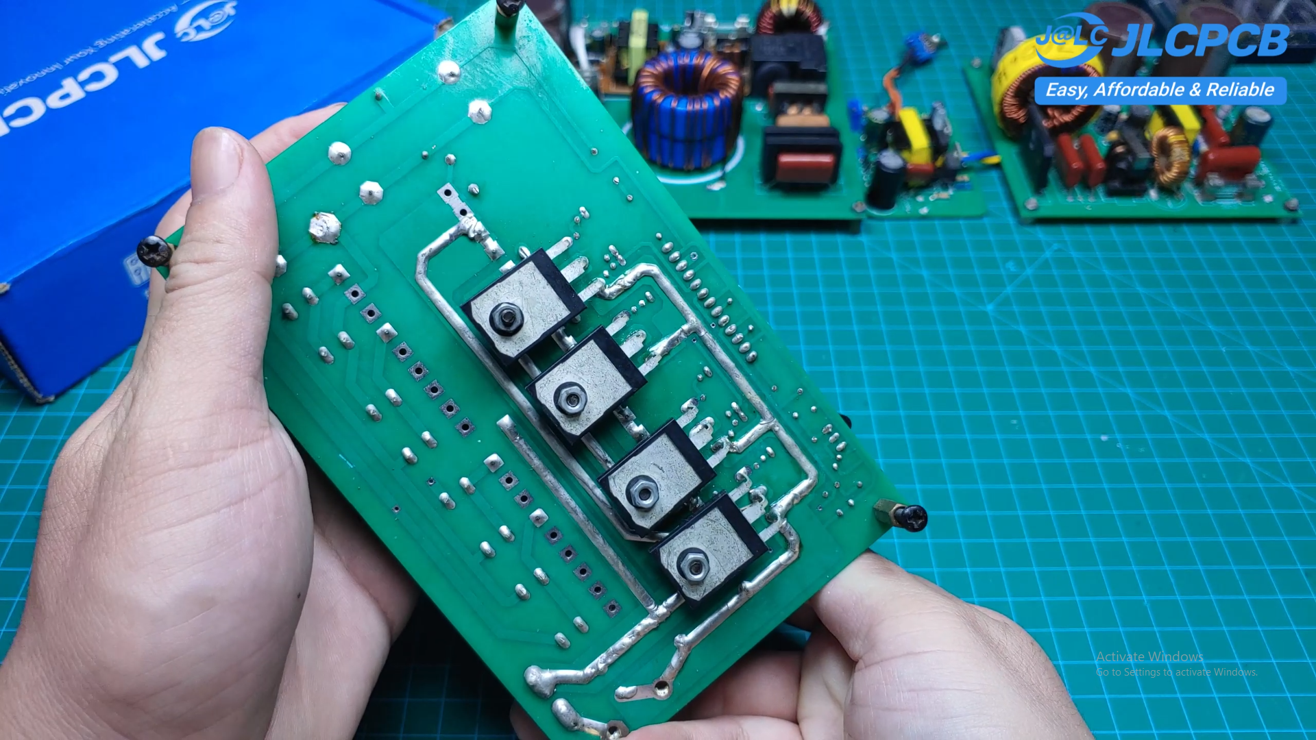
Power electronics has always been one of my favorite areas of electronics because it combines analog design, digital control, magnetics, PCB layout, and high-power engineering into a single project. Over the past few years, I have designed and tested many inverter and Power Factor Correction (PFC) circuits. In this article, I'd like to share four of my most successful projects, complete with schematics, PCB designs, and practical implementation.

Supplies

Components

  • PCB boards
  • SG3525 PWM controller
  • NCP1653 PFC controller
  • IRF3205 or IRFZ44 MOSFETs
  • Ferrite transformers
  • Ferrite cores for custom inductors
  • Electrolytic capacitors
  • Fast recovery diodes
  • Power resistors
  • Connectors and terminal blocks
  • Miscellaneous resistors and capacitors

Tools

  • Soldering station
  • Digital multimeter
  • Oscilloscope
  • Adjustable DC power supply
  • Electronic load (optional)
  • Screwdrivers
  • Wire cutters
  • Solder wire
  • Flux

PCB Files

  • Gerber files (provided in this project)
  • 1
    Four DIY Power Electronics Projects – SG3525 Inverters and NCP1653 PFC Circuits

    For the past few years, I've been designing and building power electronics circuits as both a hobby and a learning experience. In this project, I'd like to share four of my favorite designs that have been thoroughly tested and successfully operated.

    The collection includes two inverter designs based on the SG3525 controller and two Power Factor Correction (PFC) circuits based on the NCP1653. Together, they cover everything from a compact portable inverter to a high-power 2.5 kilowatt PFC converter.

    All of the PCB boards shown in this project were manufactured by JLCPCB.

  • 2
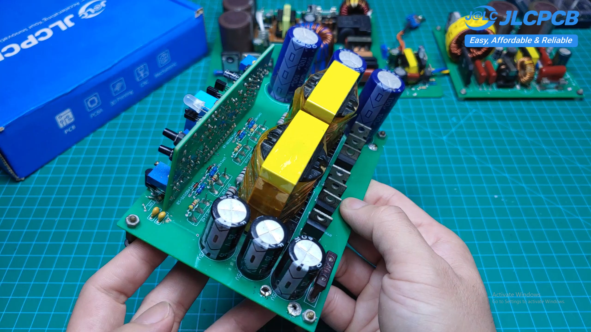
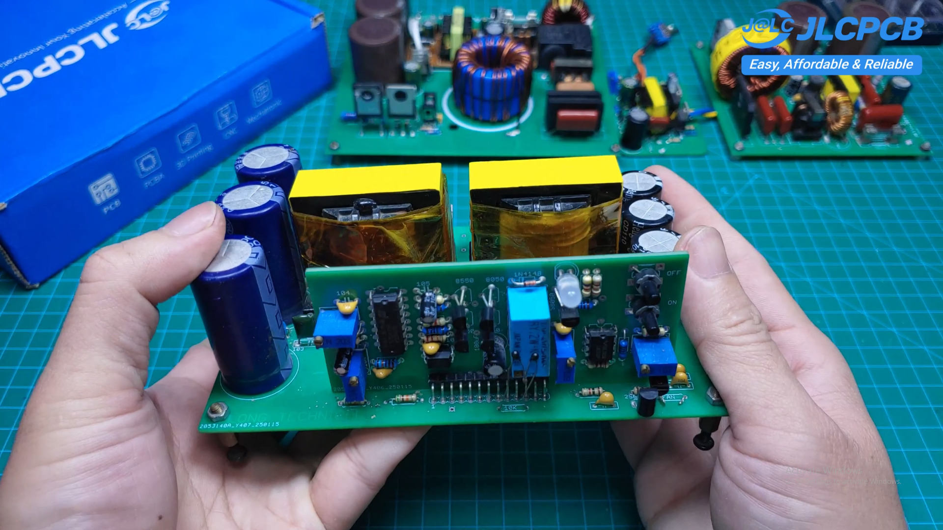
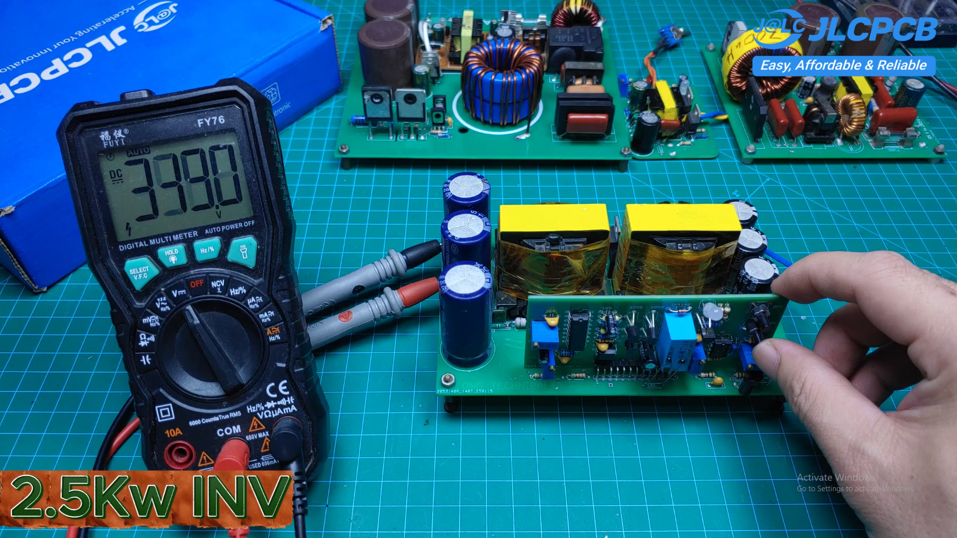
    2.5 Kilowatt Inverter

    The second project is a much larger inverter capable of delivering up to 2.5 kilowatts.

    Instead of using a single transformer, the design employs two transformers together with an H-bridge PWM output stage, allowing the inverter to handle much heavier loads.

    Several protection features are included:

    • Soft start / soft shutdown
    • Input overvoltage protection
    • Input undervoltage protection
    • Over-temperature protection

    The inverter can comfortably power motors, fans, power tools, and many other high-power AC loads.

  • 3
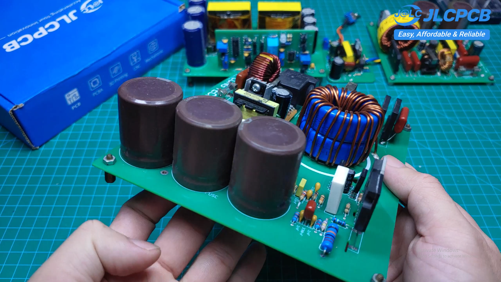
    2.5 Kilowatt PFC

    The final project is a high-power 2.5 kilowatt PFC converter.

    It is based on the same NCP1653 controller but uses a totem-pole MOSFET driver to achieve significantly higher output power.

    The control circuit is powered by a separate 15–24 volt auxiliary power supply, while the boost inductor is constructed using two stacked ferrite cores to support the higher current without sacrificing efficiency.

    This design has proven to be very stable during testing and is suitable for demanding high-power applications

View all 6 instructions

Enjoy this project?

Share

Discussions

Does this project spark your interest?

Become a member to follow this project and never miss any updates