 iliasam
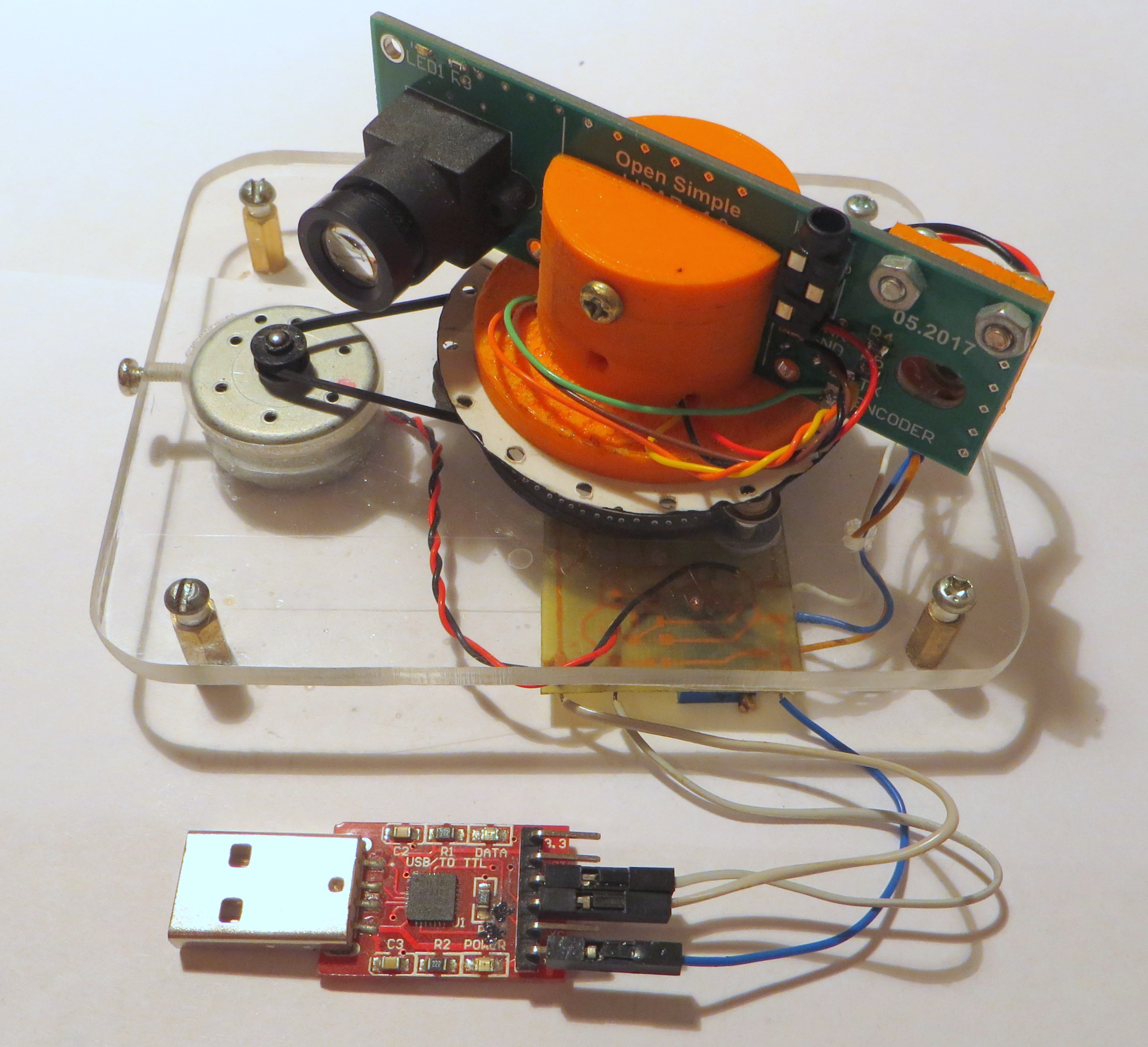
Here is the photo of the assembled LIDAR:
Last thing that I had installed is the small PCB with DC-DC converter for powering motor.
Photo of the installed board:
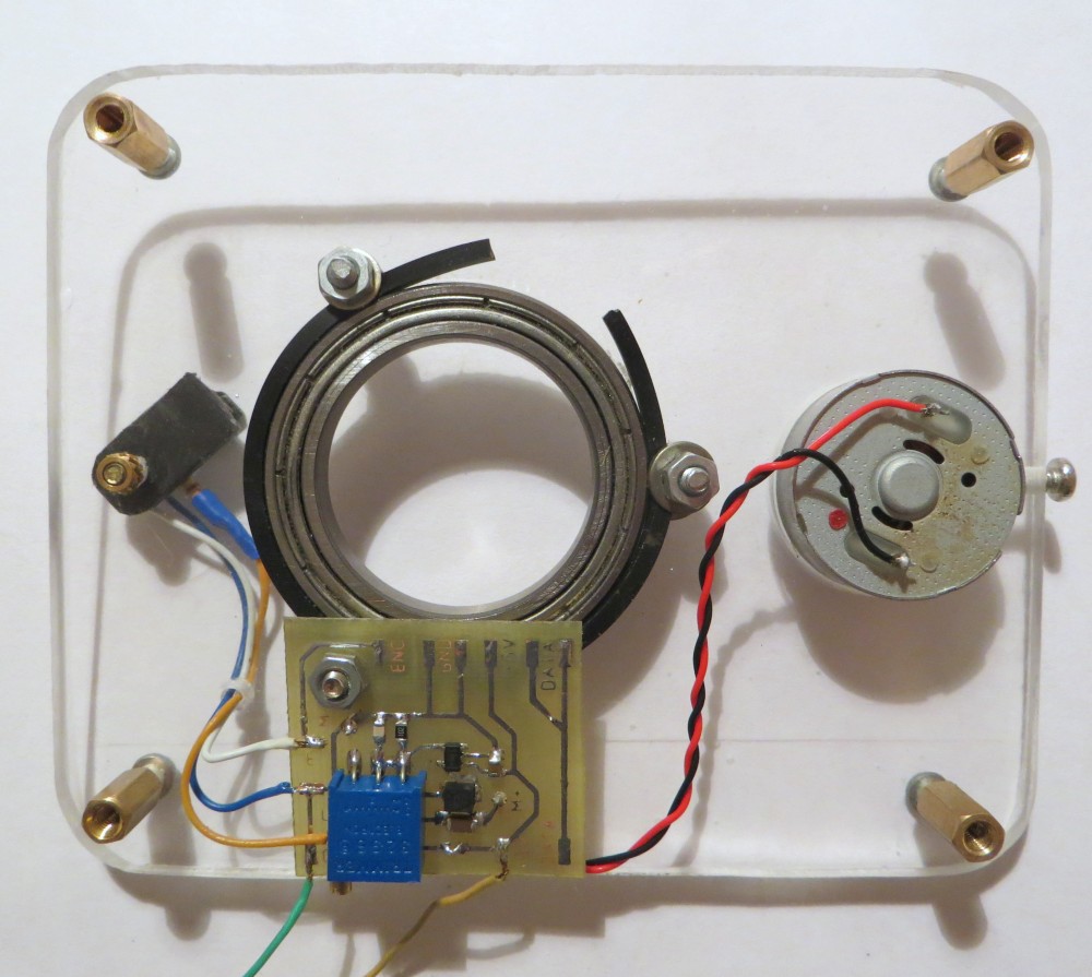
This board also simplifies connections between LIDAR's components.
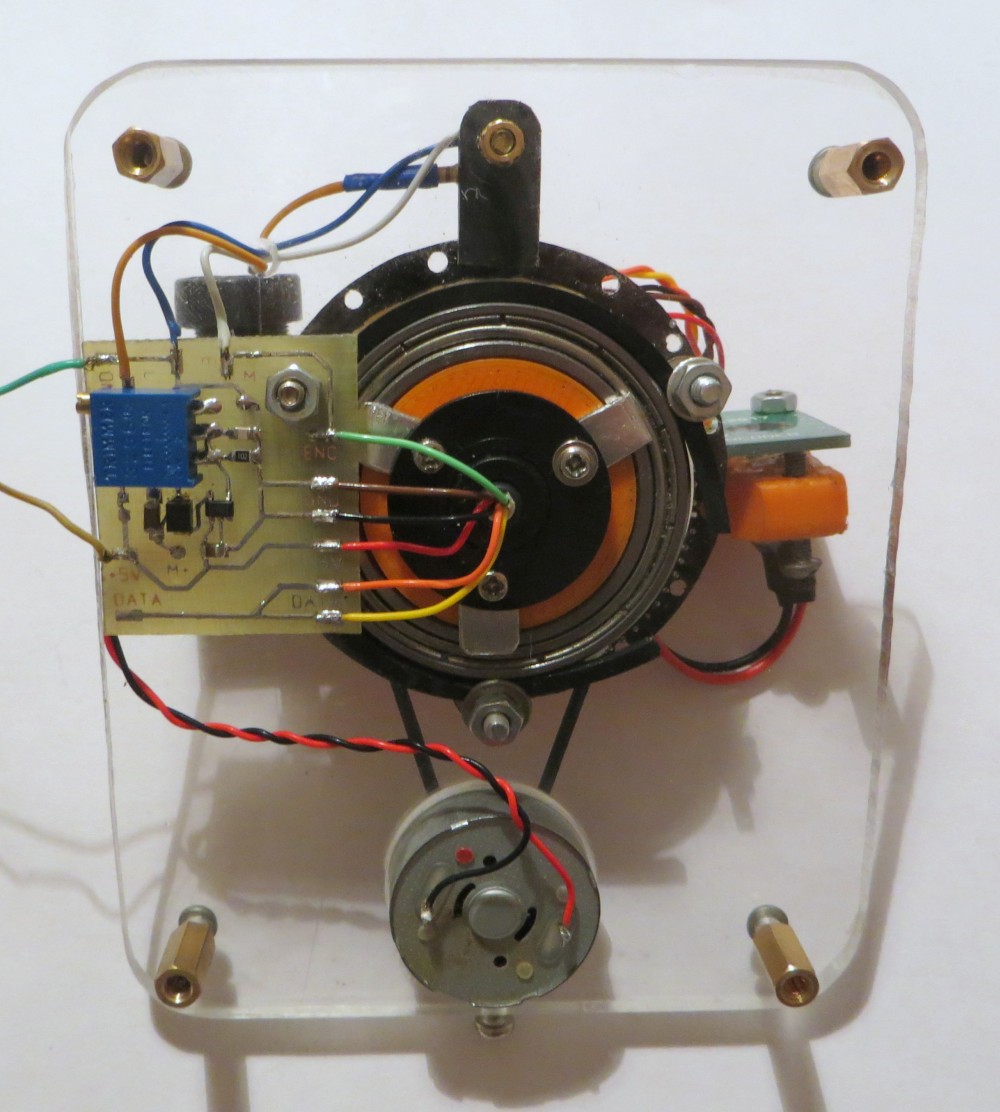
Photo with the scanning head installed:
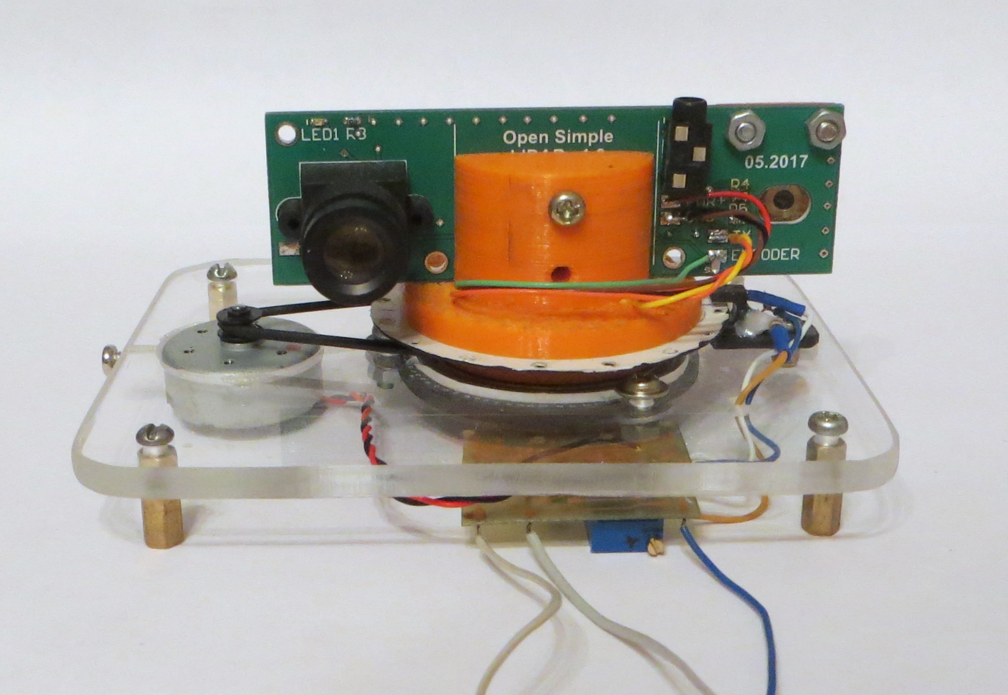
Front view of the assembled LIDAR:
My next step - write a node for ROS and to test SLAM algorithm.
Discussions
Become a Hackaday.io Member
Create an account to leave a comment. Already have an account? Log In.