 Vlad
Vlad

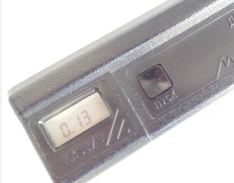
Many years ago, I bought an old Soviet dosimeter MASTER-1 at a flea market. It's a very simple device based on an SBM-20 Geiger tube and a few logic chips, designed and manufactured after the Chernobyl disaster. It has a single "Start" button to begin counting and a 7-segment, 4-digit monochrome LCD display to display the results. Simple CMOS counter-based logic counts Geiger tube pulses for only 36 seconds and displays the result with a fixed decimal point. For the SBM-20 Geiger tube, these 36 seconds mean that the number of pulses is expressed as a dose rate in microroentgens per hour, so after dividing by 100, this becomes microsieverts.
Photo from internet:
Suddenly it stopped working. At first, I tried to fix it but then I decided to rebuild it completely with using only Geiger tube and a covering case.
It looked like the following:
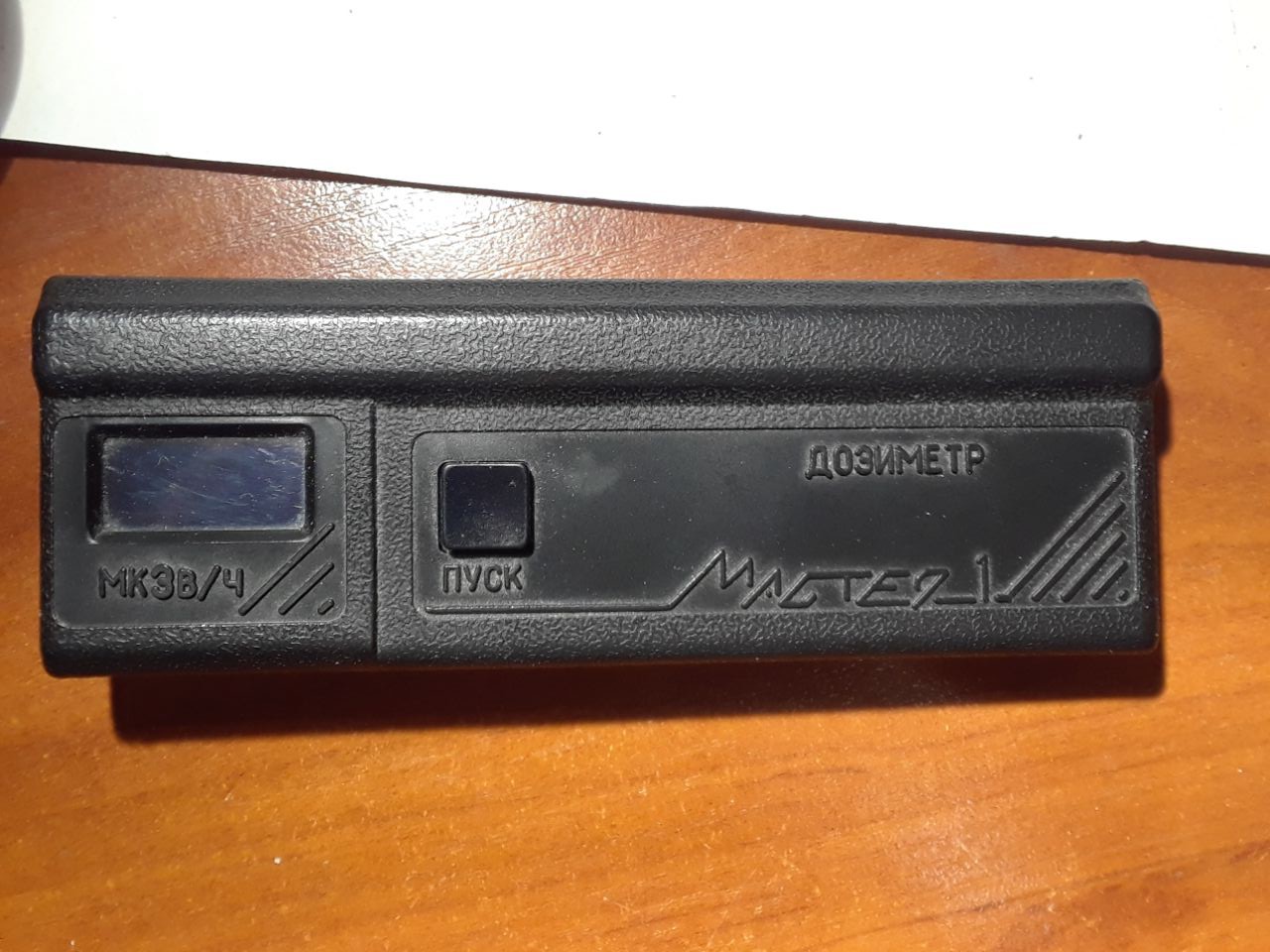
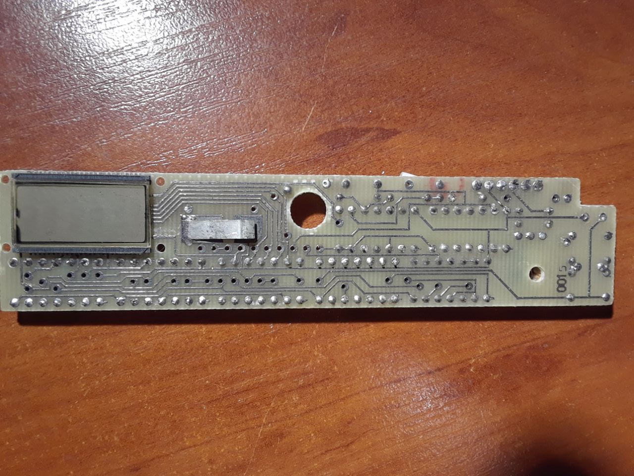
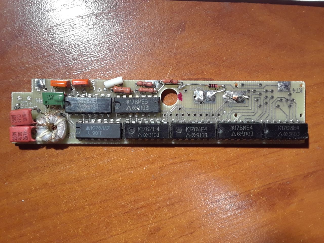
Actually, I took these photos today, so some components had already been removed from the PCB...
My requirements for the device were as follows:
1. It should be wearable. This is easy because it's quite small.
2. It should be rechargeable. Okay, just use a LiPo battery of the appropriate size and a built-in charger.
3. It should log measurements and provide the ability to download them to a PC.
4. It should log geolocation so I can walk around with it and see the measurements on a map.
After researching the microcontroller market, I found the Seeed XIAO BLE nRF52840 board, which includes a lithium-ion battery charger and a Bluetooth BLE module. It perfectly met my requirements 1, 2, and 3, except for GPS, but I realized that fitting a GPS receiver in such a small enclosure would be impossible. Thanks to the presence of Bluetooth, I decided to use a smartphone for geolocation.
A 2-color OLED 0.95" 128x64 I2C display based on SSD1306 perfectly fits instead of original LCD display. Well, the bottom 8 pixels are not visible actually, but that's fine.
The circuit diagram is very simple, and I didn't even draw it on paper, so it existed only in my head. I'm trying to recreate it from memory:
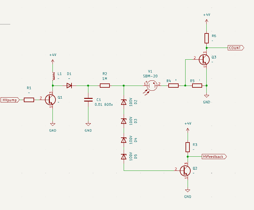
Something like this, perhaps a couple of additional capacitors for stability. And, of course, another transistor for the speaker to beep with each registered particle.
HVpump is connected to the microcontroller output generating pulses based on the HVfeedback input signal.
COUNT is connected to the microcontroller input for counting Geiger pulses.
That's basically it. Assembled, it looks like this:
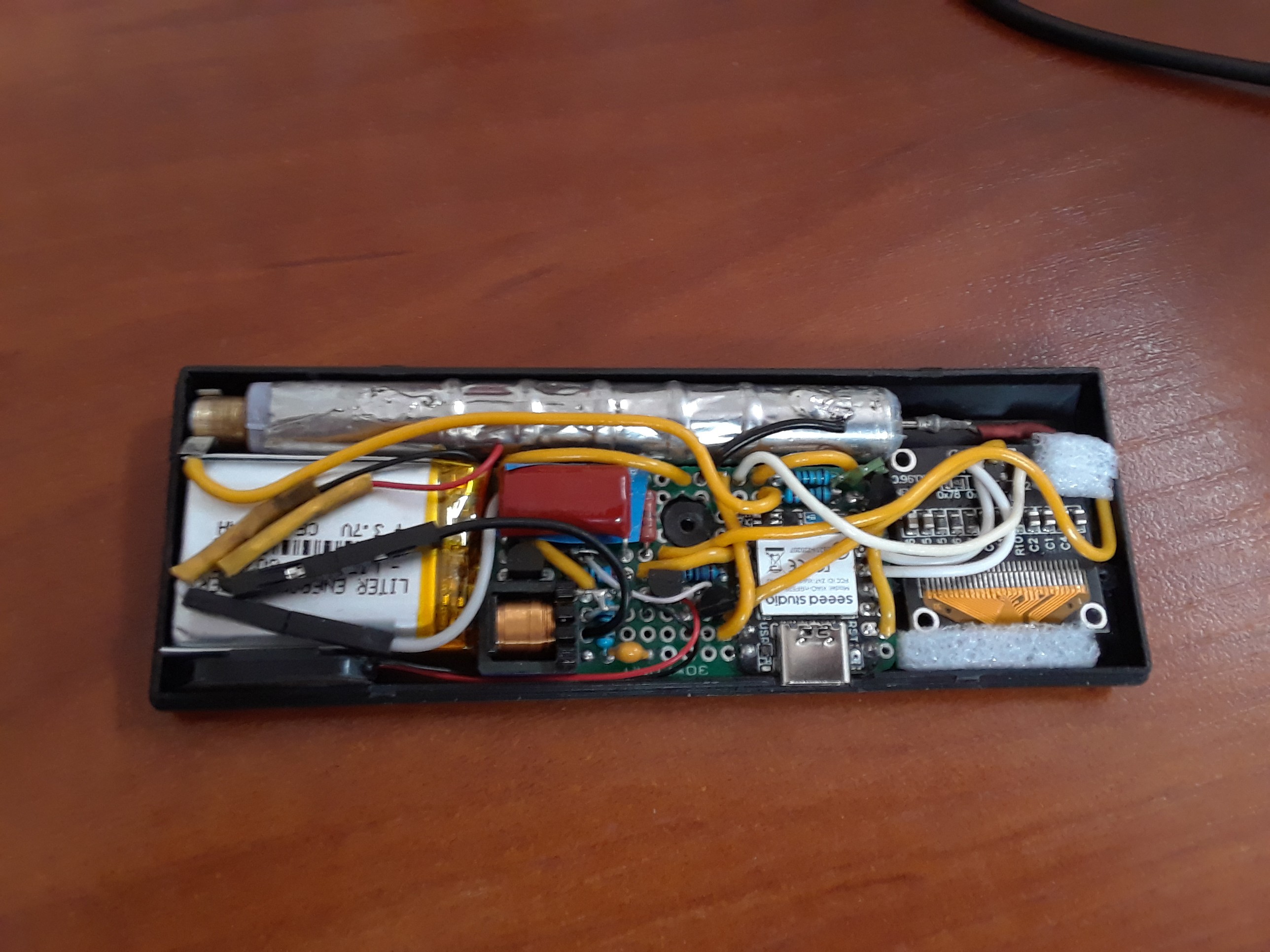
All components are placed on a stripboard, the shape of which fits the space available. The microcontroller's USB-C port is used for charging the battery and connecting to a PC for downloading log files.
Everything else is software. The firmware for the nRF52840 was created in the Arduino IDE, and the mobile app was created in Android Studio using Java.
The device's main screen looks like this:
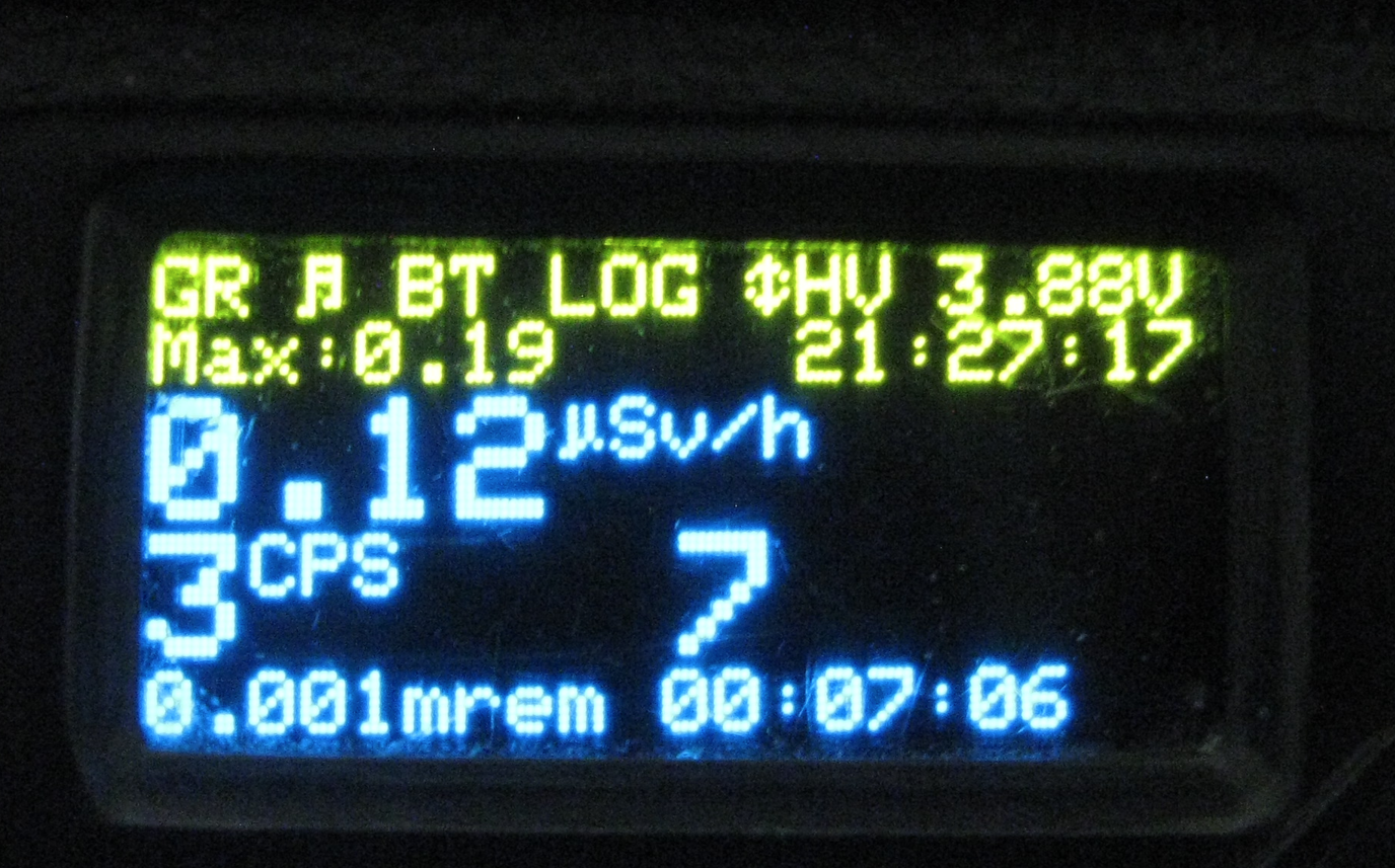
The top yellow line is the status bar, which has the following meanings:
GR indicates that the Geiger detector is enabled and counting. This can be disabled in the device menu when, for example, you want to connect to a PC via USB etc.
The music icon indicates that the sound is on. This can be replaced by an "A" symbol if the sound is muted but the alert function is enabled, meaning the sound will automatically turn on if the dose rate exceeds 0.5 µSv. If the sound and the alert are disabled this placeholder is empty.
BT means Bluetooth is enabled. By default, it's disabled at system-on and can be enabled through the main menu if you need to connect a smartphone.
LOG means data logging is enabled. The board has 2 MB of flash memory, which is used as a FAT partition to store the log file. Another option is "USB" mode, which can be enabled in the main menu, allowing you to connect the device to a PC as a USB drive to download the log file.
The "double arrow" icon indicates that the high-voltage pump is constantly on to monitor the high-voltage feedback...
Read more »