Arnov Sharma

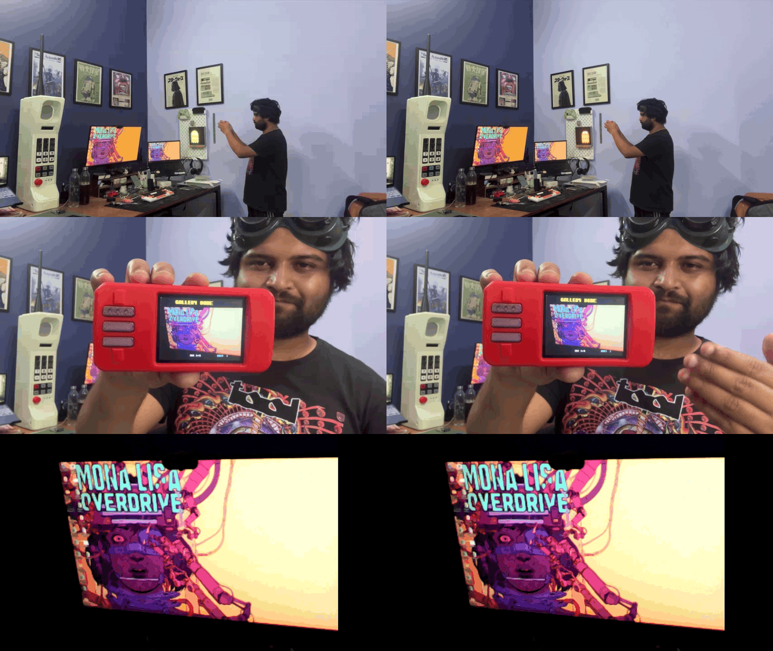
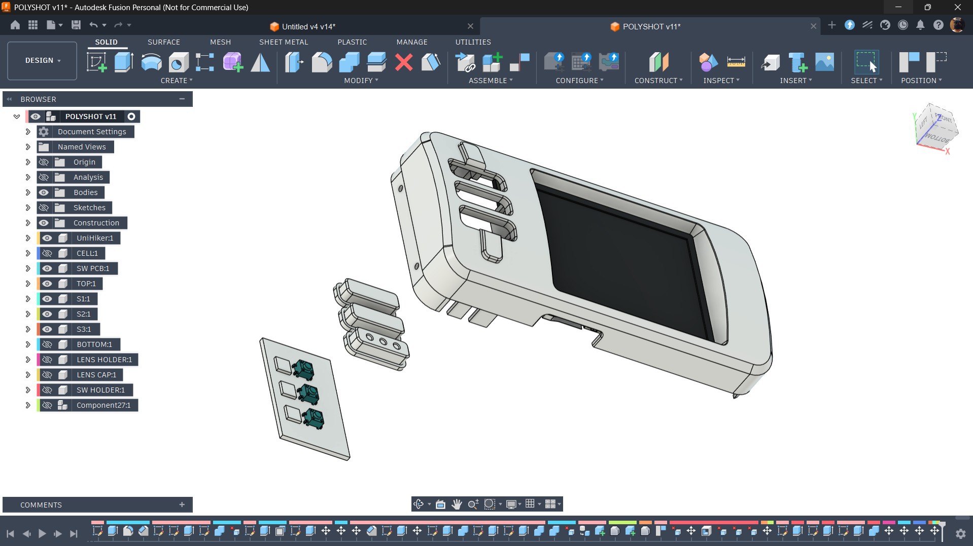
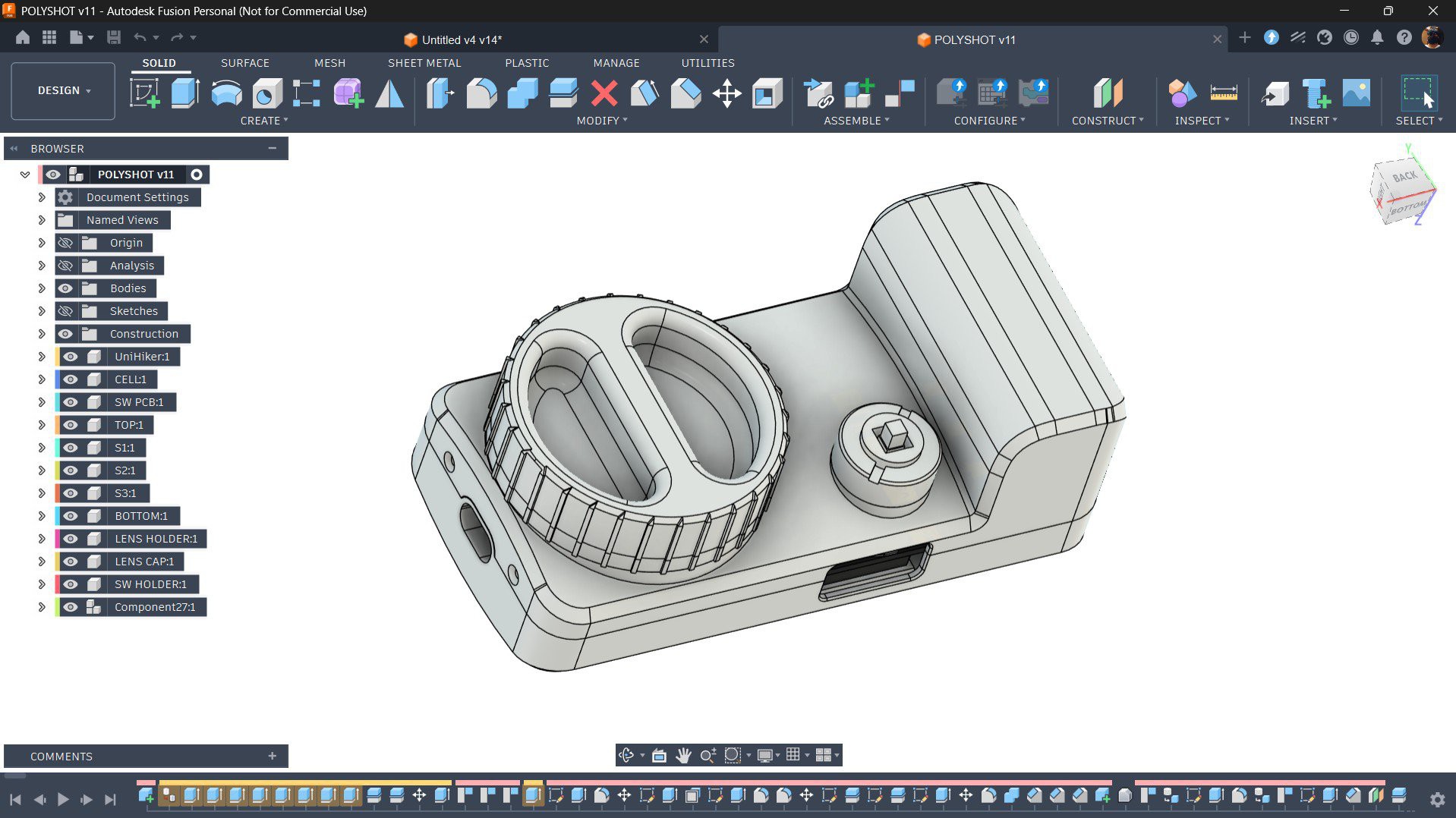
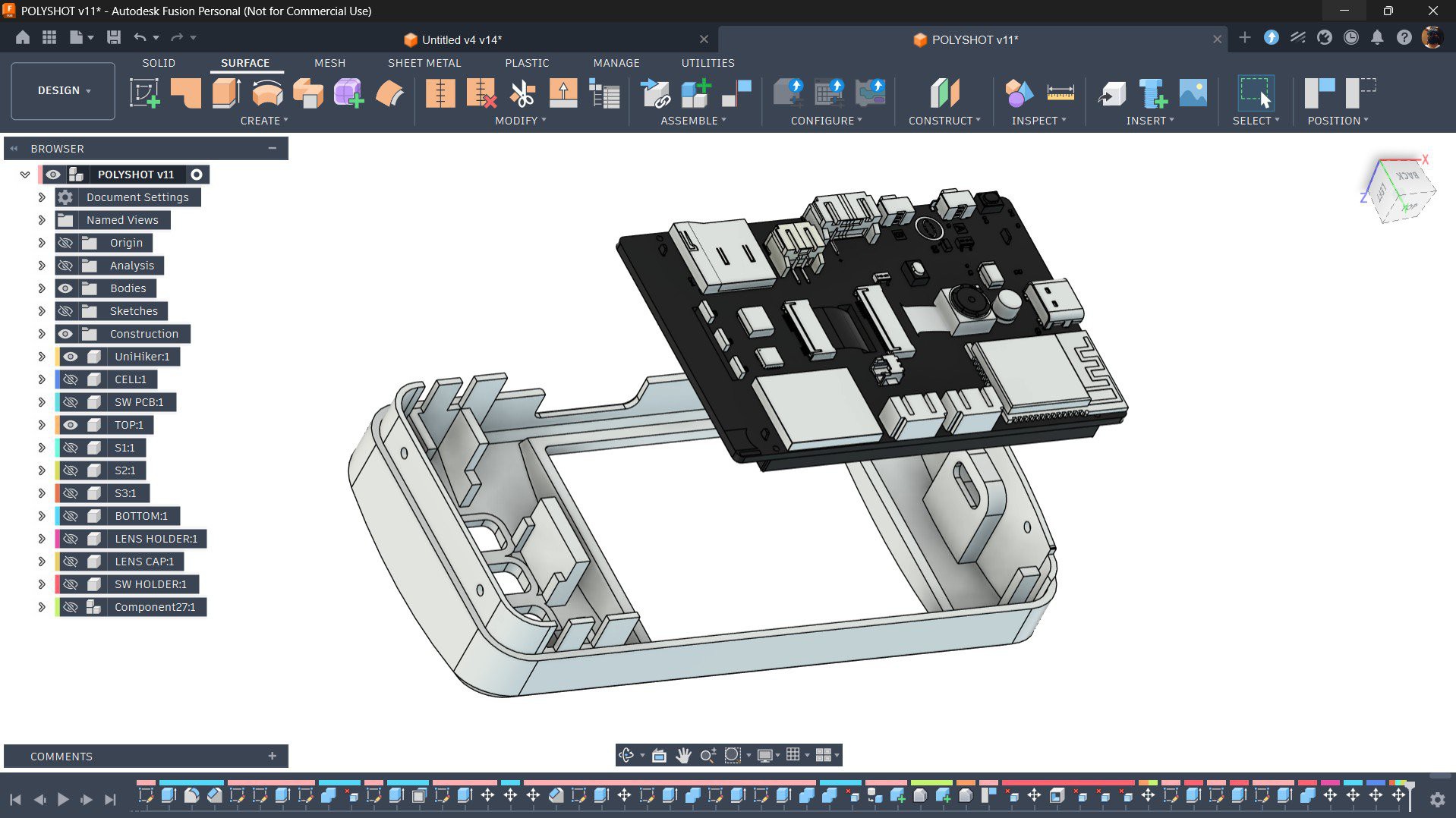
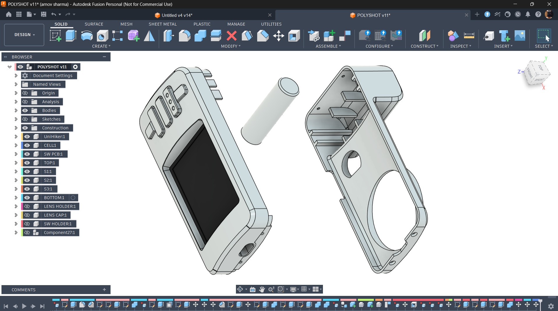
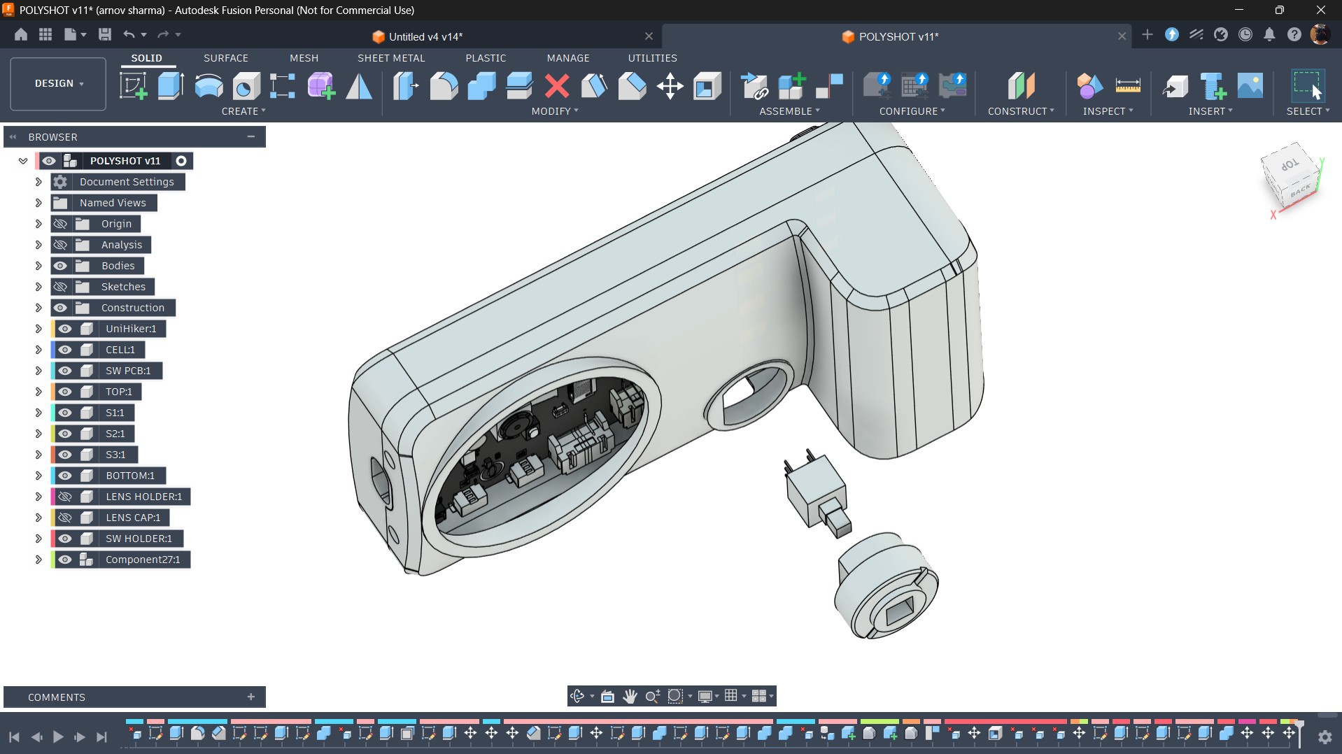
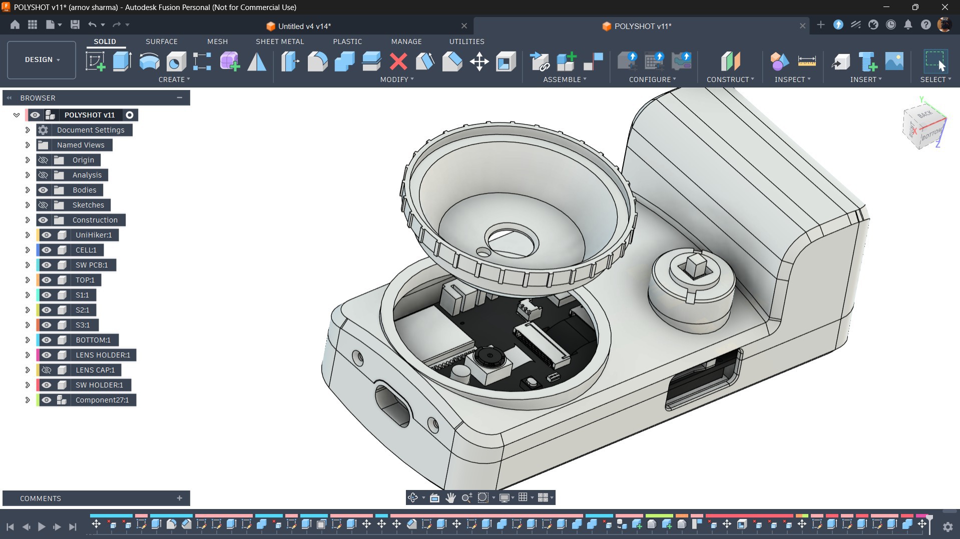
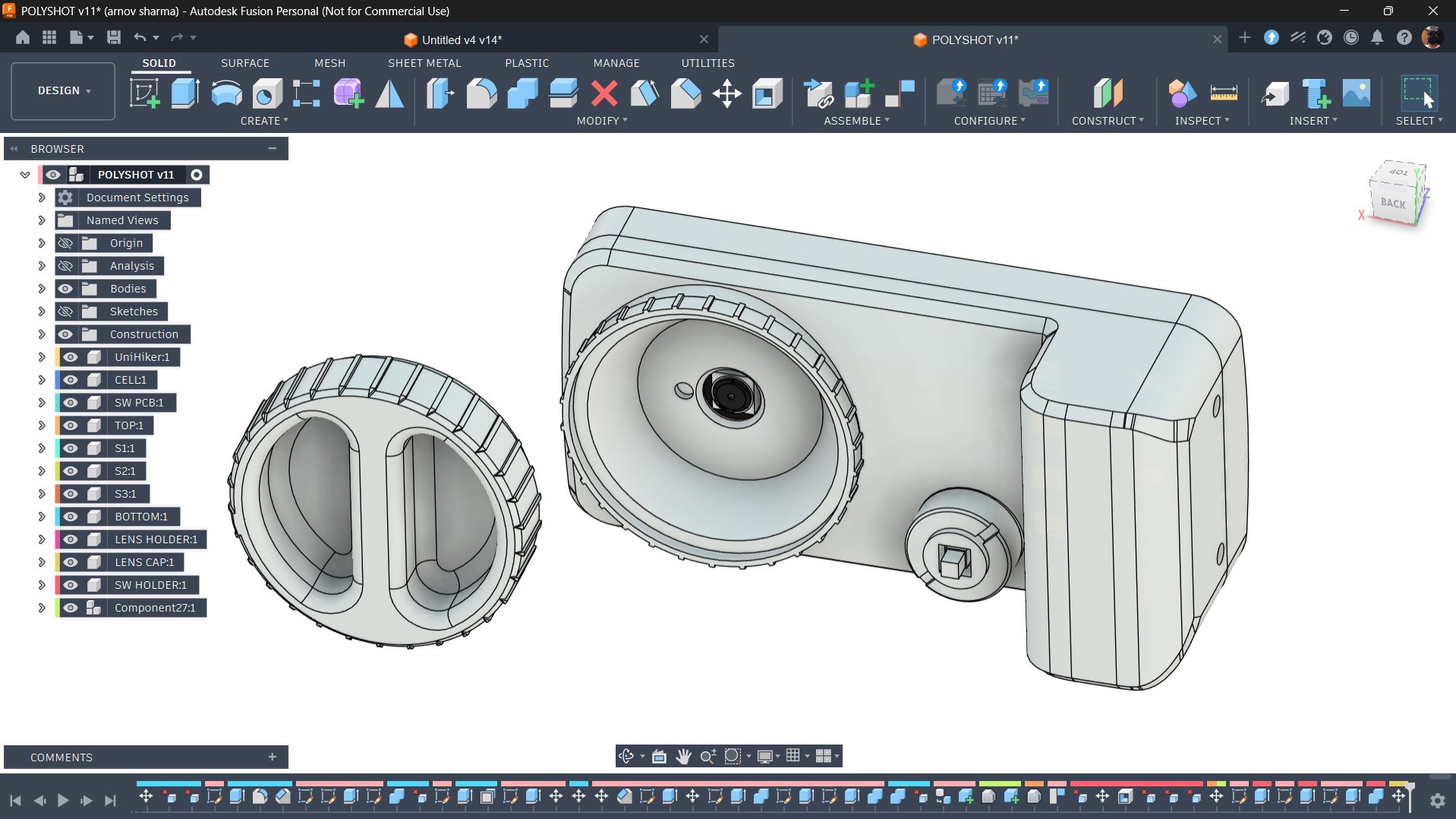
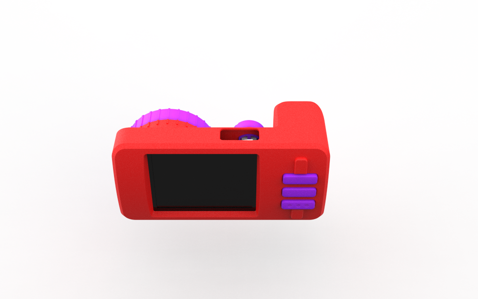
At the heart of this project is the UNIHIKER K10 development board, which is powered by the ESP32-S3 and features a built-in 2-megapixel camera. I designed a custom enclosure for the camera along with a custom button PCB that connects to the UNIHIKER board through its edge connector.
The UNIHIKER also has a microSD card slot, where all captured photos are stored as BMP images. These images can either be viewed directly on the camera or transferred to a computer by simply removing the SD card.
The camera works just like any basic point-and-shoot camera: you point it at your subject, press the shutter button, wait a few seconds, and the image is captured and saved to the SD card.
MATERIALS REQUIRED
These were the components used in this project.
- Custom Switch PCB (provided by HQ NEXTPCB)
- Unihiker K10 Dev Board
- SD Card
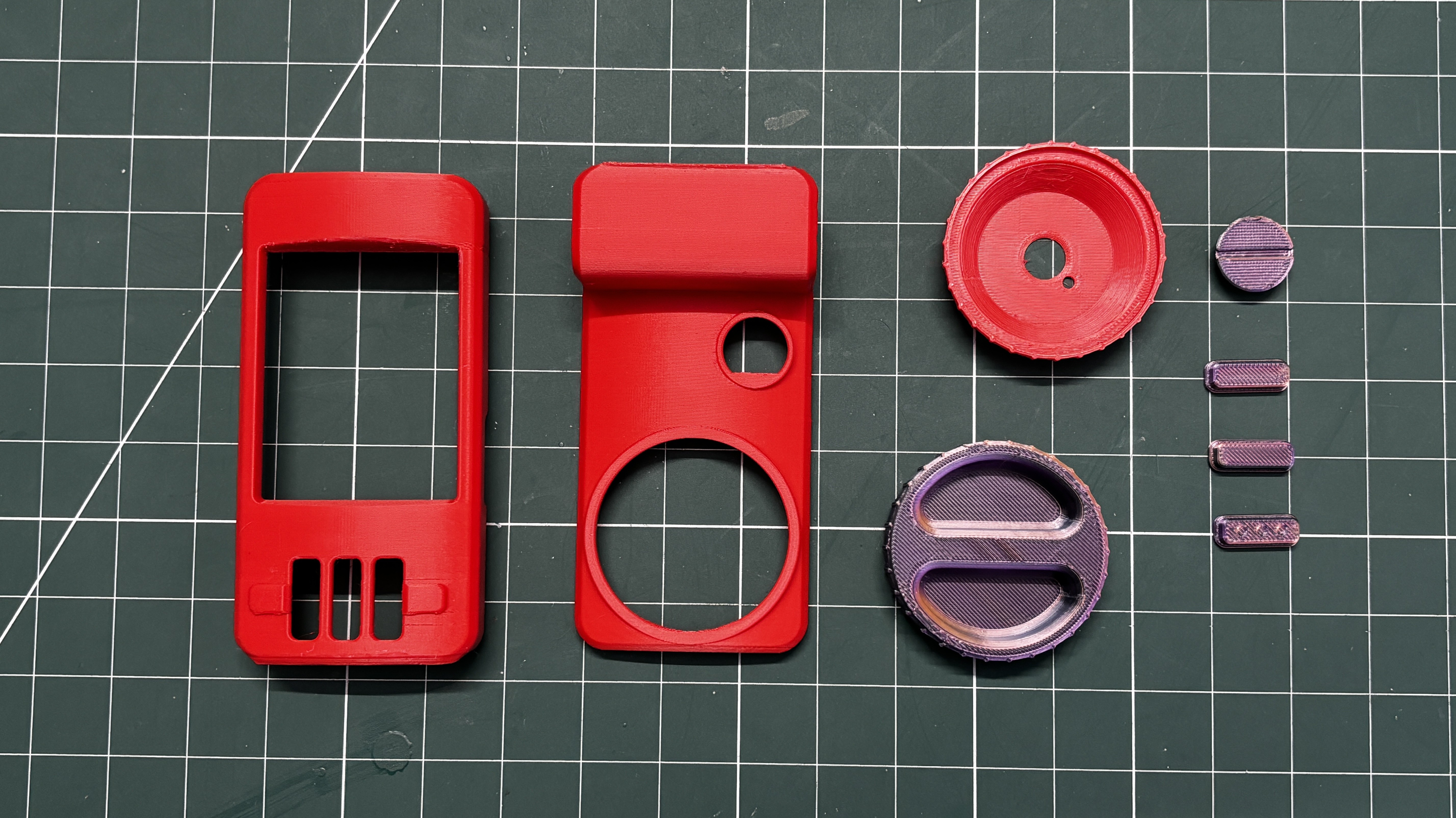
- 3D printed Parts
- M2.5 screws
- M2 self-tapping screws
- Li-ion Cell 3.7V 300mAh 1450 Package
- Push Switch
- JST Battery Connector
THE COMEBACK OF THE POINT AND SHOOT CAMERA
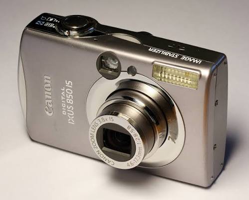
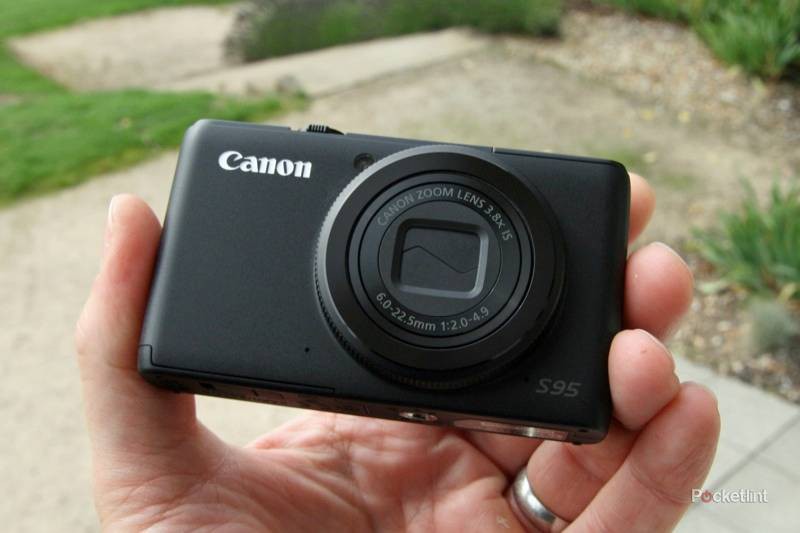

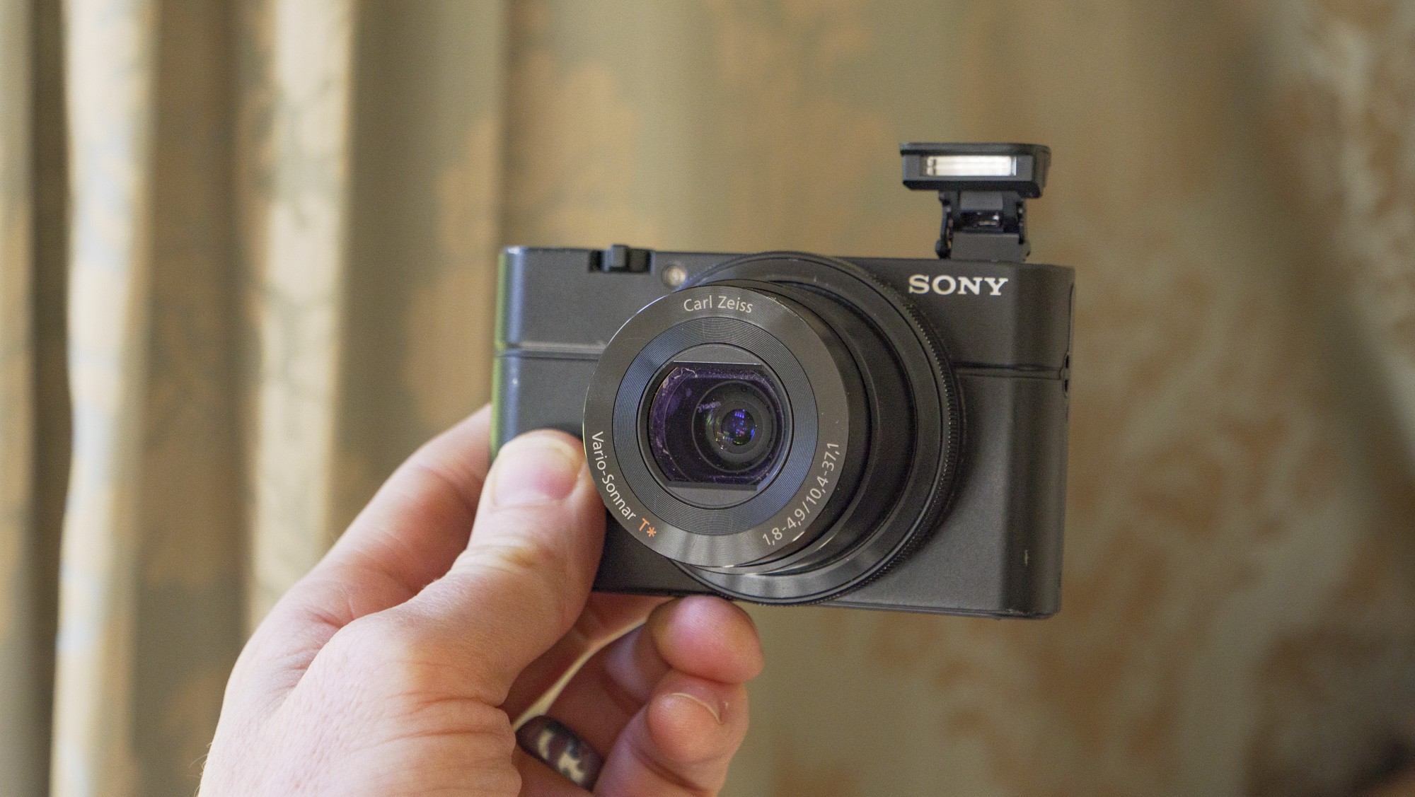
If you've spent any time on Instagram, TikTok, or YouTube recently, you've probably noticed that compact digital cameras are making a huge comeback. Vintage point-and-shoot cameras from brands like Sony, Canon, Nikon, Fujifilm, and Panasonic have become incredibly popular again, especially models from the early 2000s.
Part of the appeal is their unique image quality. Unlike modern smartphones that rely heavily on computational photography, these older cameras produce photos with a distinct look: slightly softer images, natural colors, and a nostalgic digital aesthetic that many people now prefer.
The renewed popularity has also driven up prices. Cameras that were once sitting unused in drawers or thrift stores are now being sold online for surprisingly high prices.
This was one of the reasons why I wanted to build one from scratch.
Originally, I wanted to buy a non-working camera for cheap and retrofit my own electronics inside its body, but that plan failed due to the increased prices and low availability caused by the high demand.
In the end, I had to design and build my own enclosure as well.
HARDWARE- UNIHIKER K10
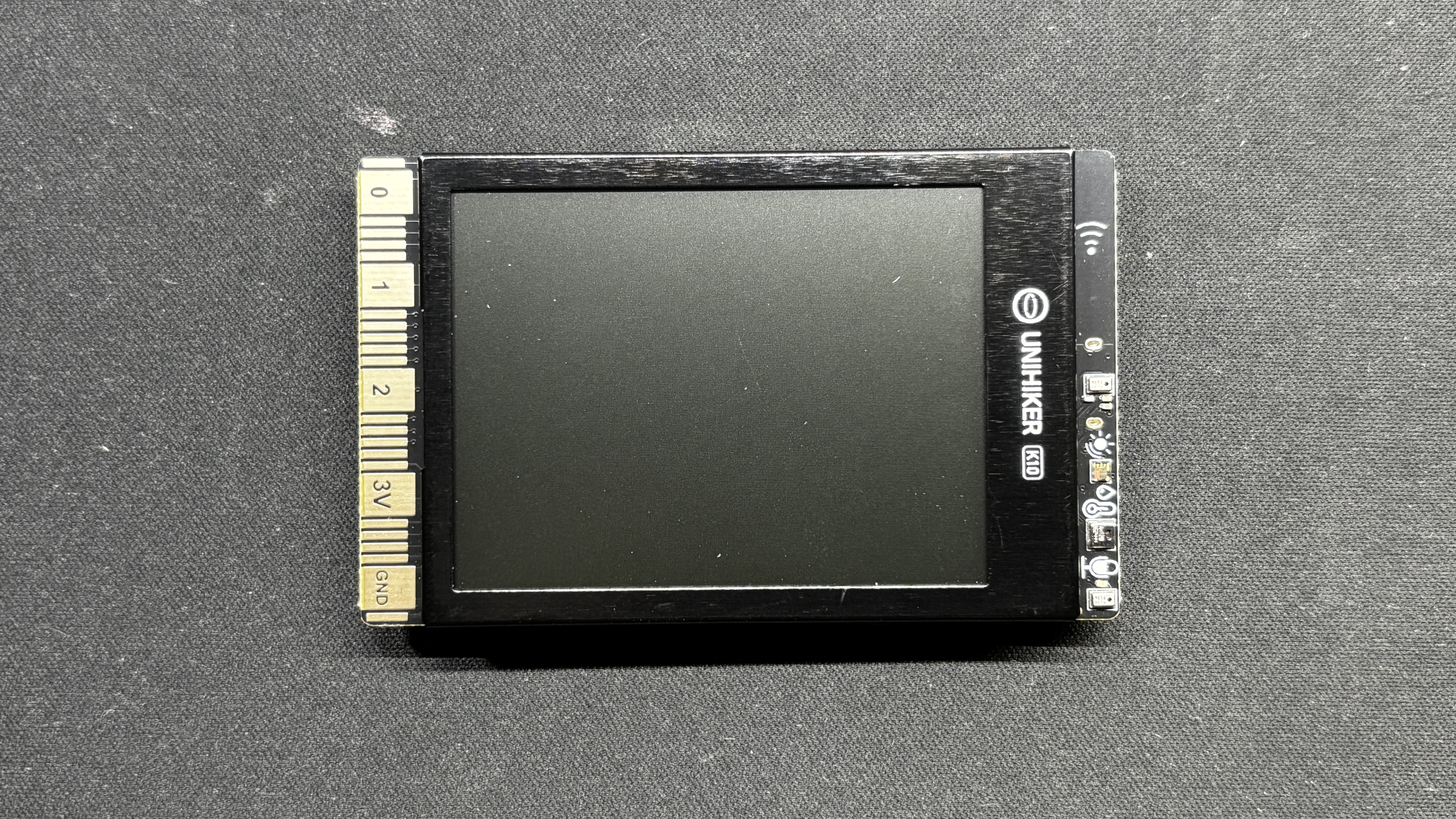
The star of this project is the UNIHIKER K10, which serves as the brain of our camera project.
The UNIHIKER platform is available in two variants: the M10 and the K10.
The M10 is based on a Linux-capable processor, designed for higher-level applications.
The K10, on the other hand, is powered by the ESP32-S3 N16R8 module; this is what we are using.
Key Specifications:
- Module: ESP32-S3 N16R8
- Processor: Xtensa® LX7 dual-core 32-bit CPU
- Clock Speed: Up to 240 MHz
- SRAM: 512 KB
- ROM: 384 KB
- Flash Memory: 16 MB
- PSRAM: 8 MB
- RTC SRAM: 16 KB
With its dual-core architecture and generous Flash and PSRAM, the ESP32-S3 is capable of handling image rendering, SD card file access, and audio playback simultaneously
Our primary reason for selecting the UNIHIKER K10 for this project was its built-in Camera, a decent 240x320 display, and SD card reader. These two features significantly simplified the overall design and eliminated the need for additional external modules.
All images will be captured and stored directly on the SD card.
Check out more about the Unihiker K10 from its wiki page.
https://www.unihiker.com/wiki/K10/
SWITCH BOARD PCB DESIGN
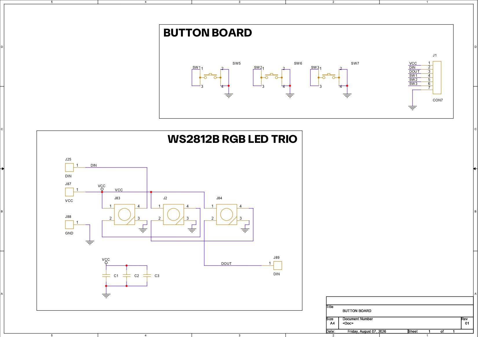

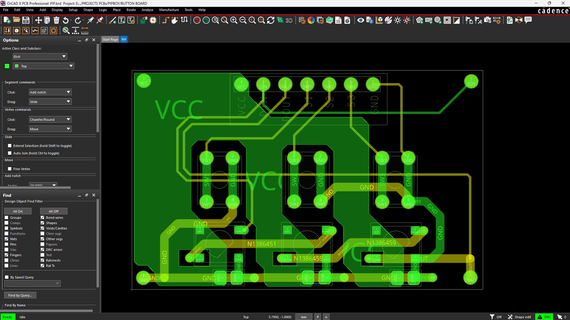
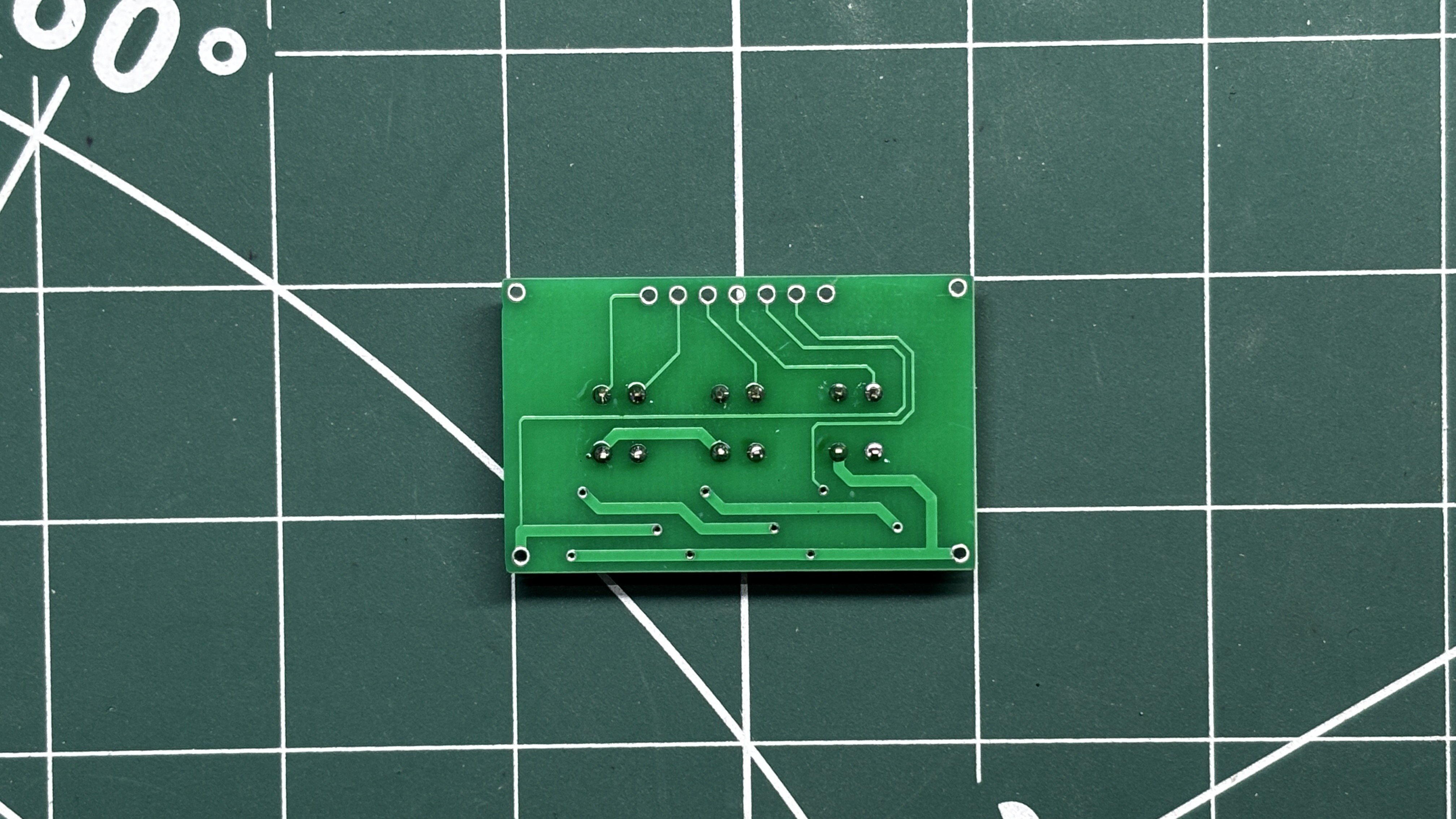
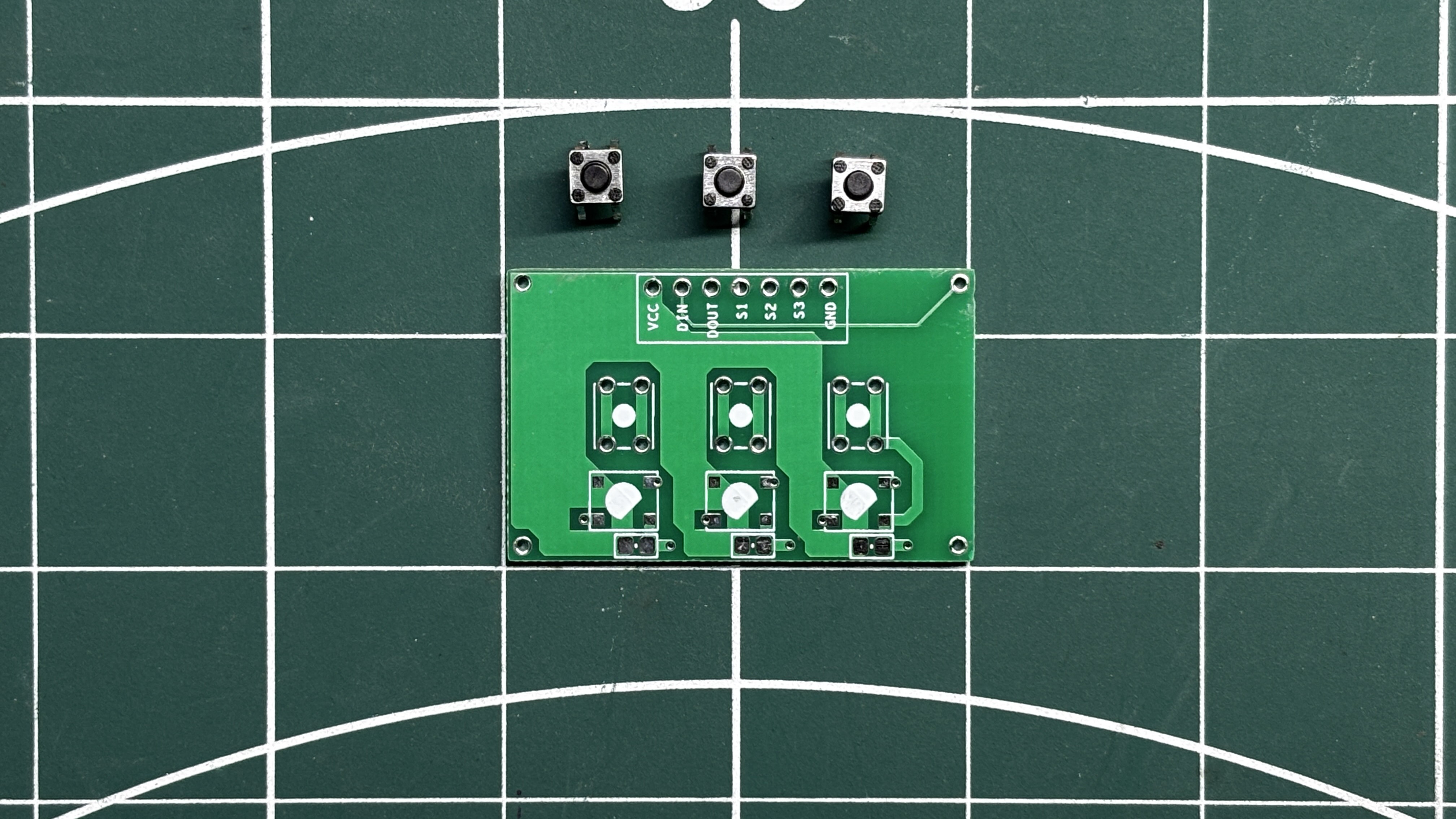
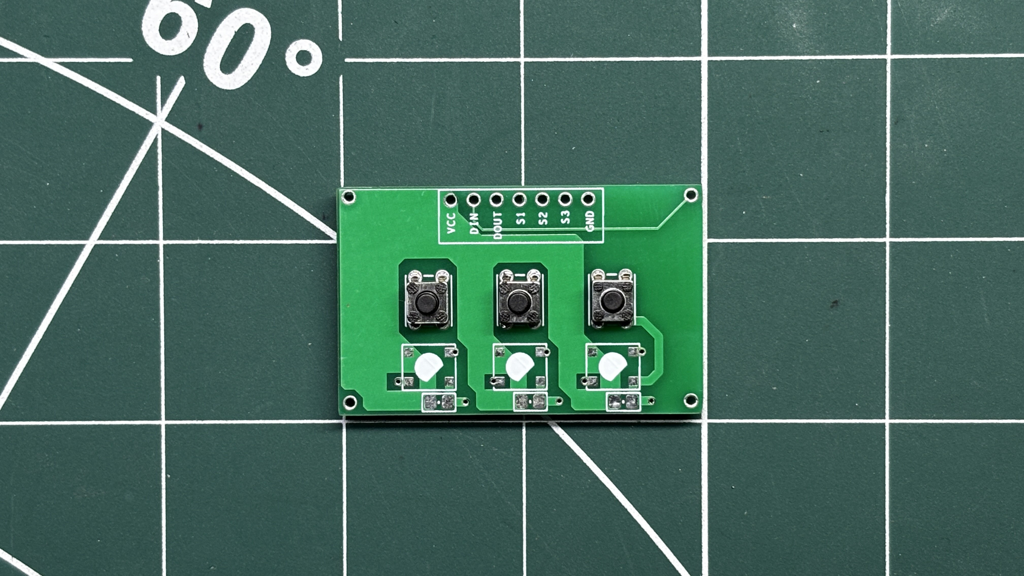
For the PCB design of this project, I needed a simple board with three buttons: one shutter button to capture an image, a second button to open the camera gallery and view the captured photos, and a third button to navigate to the next image in the gallery.
I designed a custom PCB and created the schematic, where all three buttons share a common GND connection. The second terminal of each button is routed to a 3-pin connector (CON3), which interfaces with the UNIHIKER K10.
There are also three WS2812B RGB LEDs added on board. In this project, I didn't use this feature of the board, but this is for a future project in which my plan is to use this same board but with RGB LEDs added.
NextPCB PCB SERVICE
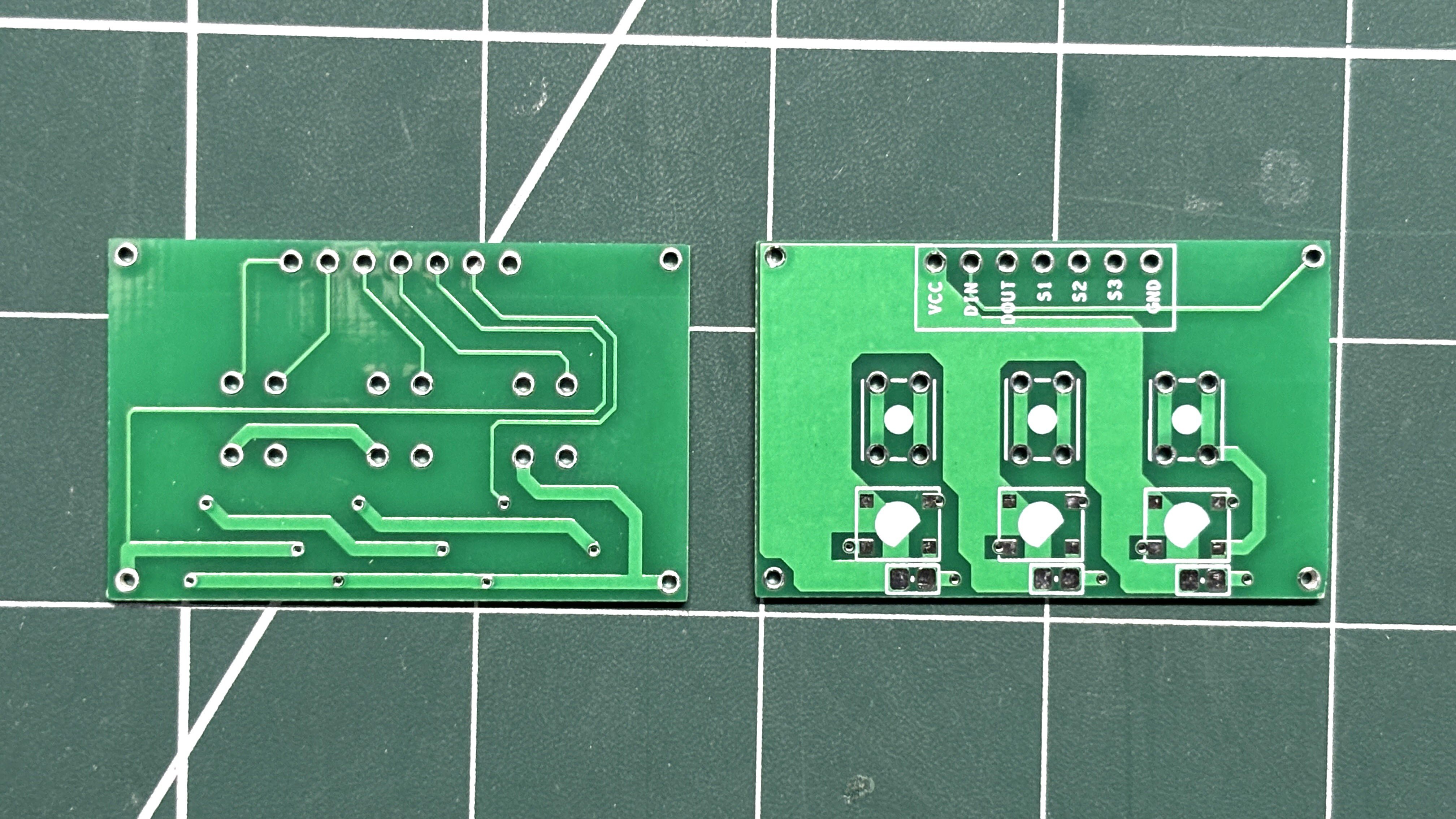
After completing...
Read more »