 Gabriel
Small update this week, no printing, no hardware, but a chunk of learning I think is worth writing up because it changes how the control system actually gets built.
I'd been saying "PID controller" for a couple posts without really understanding it, so I sat down with four different videos to actually learn it properly instead of just copy-pasting the equations.
- Introduction to PID Control — the most useful one. Derives the control law (u = Kp·e + Ki·∫e dt + Kd·de/dt) and walks through P, I, and D one at a time using error-vs-time sketches. Also does a genuinely great physical demo: a weight hanging from a rubber band (proportional), a pink string being manually pulled to represent the integrator, and then dunking the setup in water and honey to show what increasing derivative damping actually looks like.
- a shorter overview on terminology — gain vs. proportional band, integral units (repeats per minute etc), and the useful note that most real-world loops are just PI. Full PID and P-only show up sometimes, PD alone is rare. Also: most tuning in practice is trial and error, not some clean formula.
- one on PID's history in industrial control, contrasting old-school ON/OFF ("bang-bang") control, like a home thermostat or a tank level that just oscillates around setpoint, with PID's ability to throttle continuously instead of just slamming on/off.
- a terminology-focused one covering setpoint, process variable, control variable, and error, using a thermostat example and a gas-flow-through-a-pipe example.
To make it stick, I built a tiny live simulation in Desmos using the ticker feature: a point chasing a target using a PID loop. Desmos graph demo
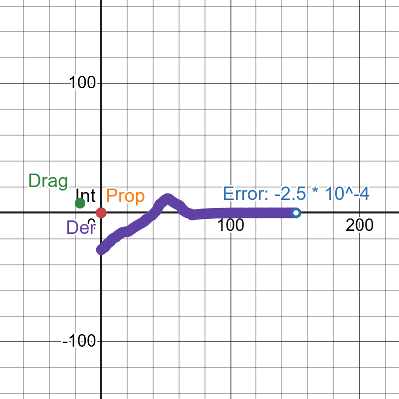
Motion is smooth, no overshoot, but I'll be upfront: the gains in there are completely arbitrary. I haven't tuned P, I, or D against anything real, this was just to get the shape of the behavior right before I touch actual hardware.
The control flow got simpler
The bigger thing this week was redoing Handy's control flow diagram in Figma. The idea hasn't changed from my last post: a shared neural net producing gains, feeding five independent per-motor PID loops. But the old diagram was overcomplicated in a way that made it harder to build, not easier.
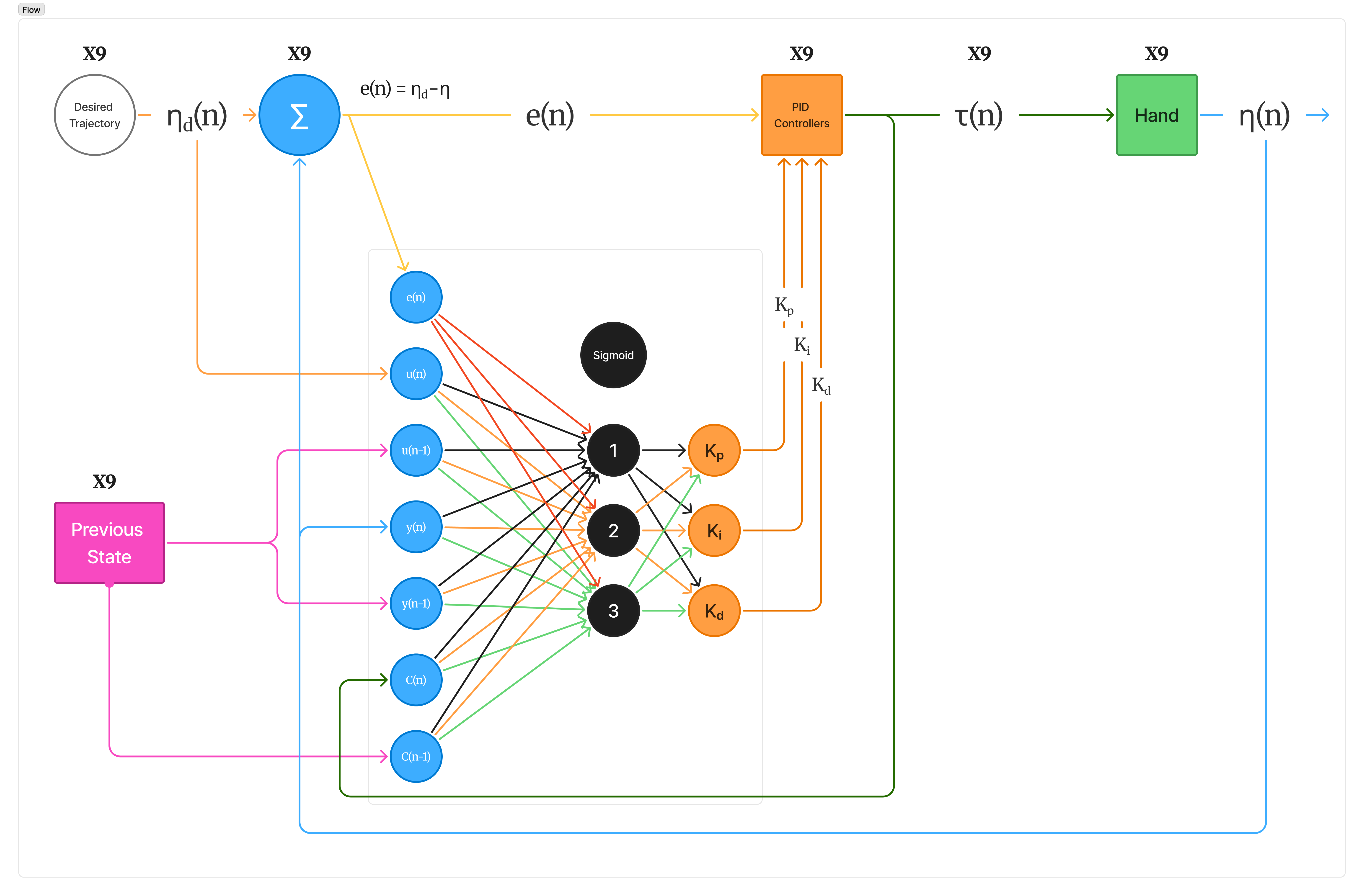
Roughly how it reads: desired trajectory and the hand's current output get compared to produce an error signal. That error, plus some previous-state values, feeds a small neural net with a sigmoid hidden layer, which outputs Kp, Ki, and Kd. Those gains go into a PID controller along with the error, and the PID output is the torque sent to the hand. The hand's new output feeds back into both the error comparison and the previous-state block, closing the loop.
That loop runs five times, once per finger. (The diagram currently says x9 in a couple spots, that's a labeling mistake, it should say x5.)
Next step is actually tuning the gains instead of eyeballing them, probably back in the Desmos sandbox before it touches real hardware.
Discussions
Become a Hackaday.io Member
Create an account to leave a comment. Already have an account? Log In.