Salah_Eddine
1. Hardware Configuration
After opening SIMATIC Manager, the “New Project Assistant” window may appear. You can simply close it, as we will create the project manually.
Right-click in the project area and select:
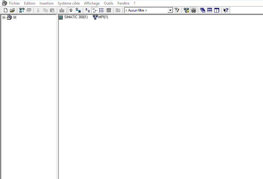
Insert → Station → SIMATIC 300 Station
For this project, I will use an S7-300 station.
 1.1 Adding the Hardware
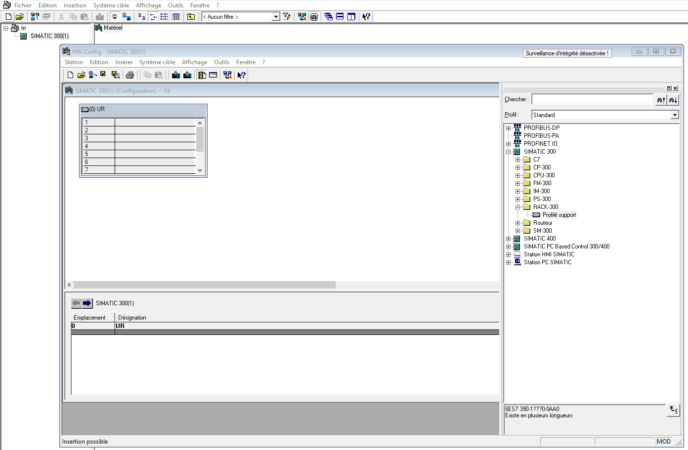
After creating the station, select it and double-click Hardware to open the HW Config editor.
On the right side, you will find the Hardware Catalog. If the catalog is not visible, go to:
View → Catalog
From the Hardware Catalog, navigate to:
SIMATIC 300 → RACK-300
Select the Rail and drag it into the configuration window.
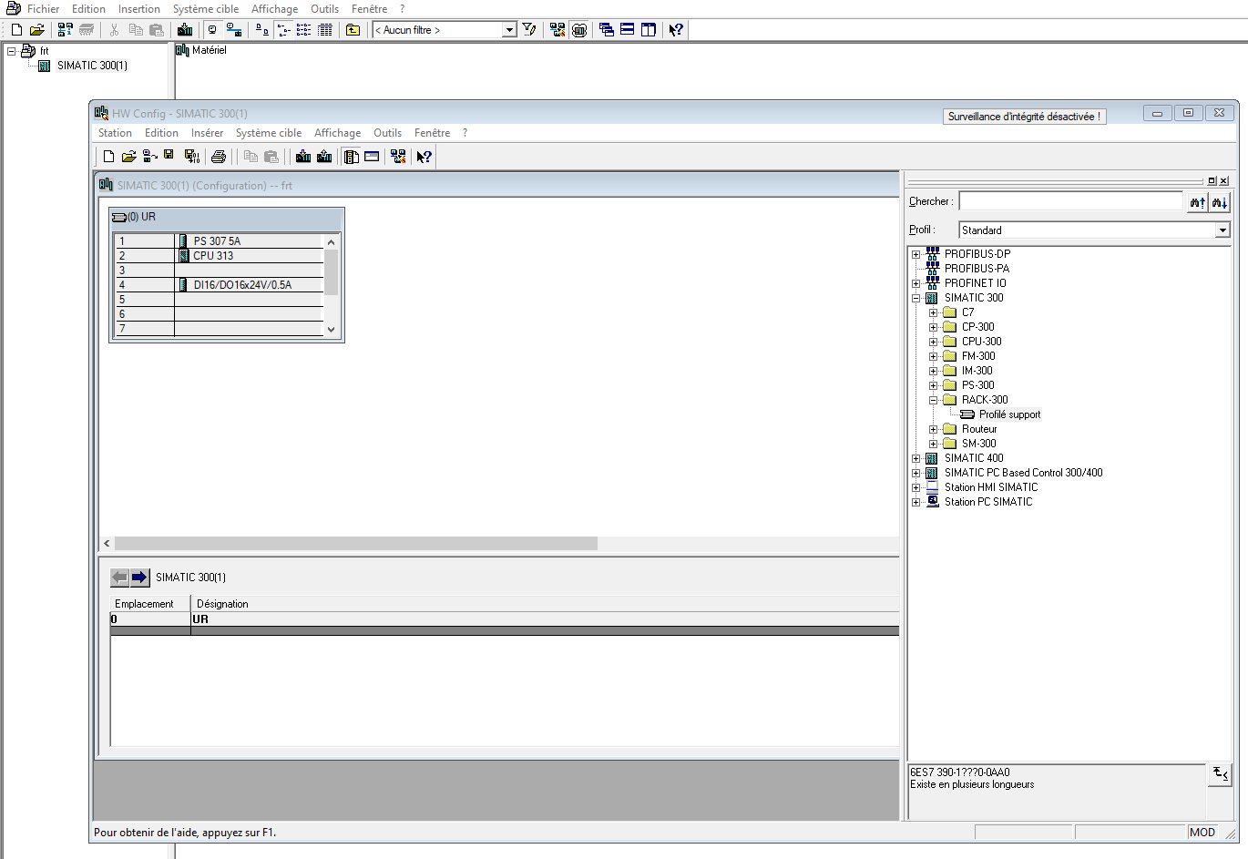
For the S7-300 hardware
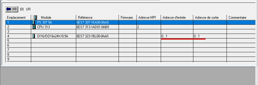
configuration, I added the required modules and arranged them according to the standard rack layout. The following image shows the complete hardware arrangement, including the power supply, CPU 313, and I/O modules.
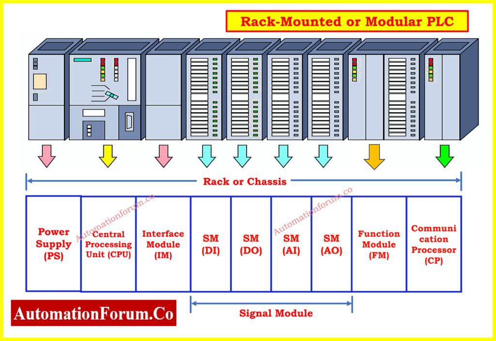
Make sure that the selected CPU and its order number match the CPU you intend to use.
1.2 Adding the Digital I/O Module
If the project requires additional digital inputs and outputs, navigate to:
SIMATIC 300 → SM-300
Select the required digital input/output module and place it in the appropriate slot.
For this DOL motor control project, the digital inputs will be used for commands such as Start and Stop, while a digital output will control the motor contactor.
1.3 Saving and Compiling the Hardware Configuration
After placing all required modules, save the hardware configuration and compile it using:
Station → Save and Compile
The hardware configuration is now ready for programming in STEP 7.
2. Configuring the PLC Program
After completing the hardware configuration, save and compile the station.
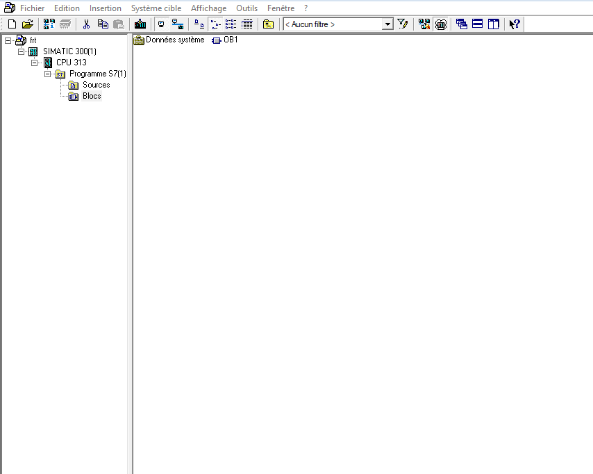
Next, return to the SIMATIC Manager and open the S7 Program under the configured CPU.
The main program will be created in OB1 (Organization Block 1). This is where I will implement the basic logic for controlling the motor.
2.1 Creating the Motor Control Logic
For this project, I will use Ladder Logic (LAD) to program the motor control sequence.
I will use two push buttons:
- Start — Normally Open (NO): used to start the motor.
- Stop — Normally Closed (NC): used to stop the motor.
The PLC output will control the motor contactor. I will also use a self-holding circuit so that the motor remains running after releasing the Start button.
Creating the Ladder Network
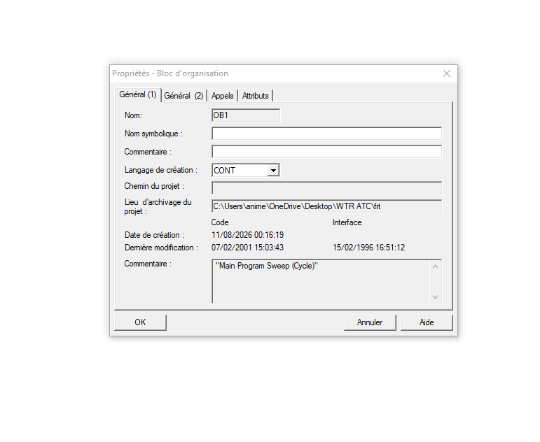
To start programming, double-click OB1 in the S7 program. A window will appear; in the Language section, select CONT to program using LAD (Ladder Logic), then click OK.
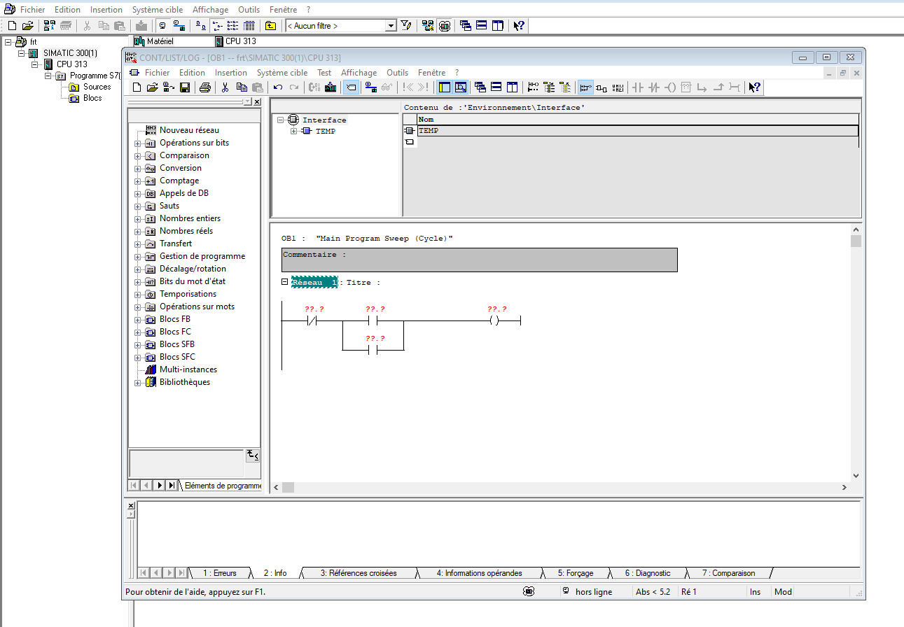
The Ladder Logic editor will open.From the instruction toolbar, I will select the required contacts and place them in the network.
For the motor control circuit, I will use:
- A Normally Closed contact for the Stop button.
- A Normally Open contact for the Start button.
- A Normally Open contact associated with the motor output for the self-holding circuit.
- A coil for the motor contactor output.
2.2 Assigning Inputs and Outputs
The next step is to assign addresses to the physical inputs ''E'' and outputs ''A''.
For example:
- Start push button → Digital Input
- Stop push button → Digital Input
- Motor contactor → Digital Output
The exact addresses depend on the digital I/O module used in the hardware configuration.
2.3 Defining the Mnemonics
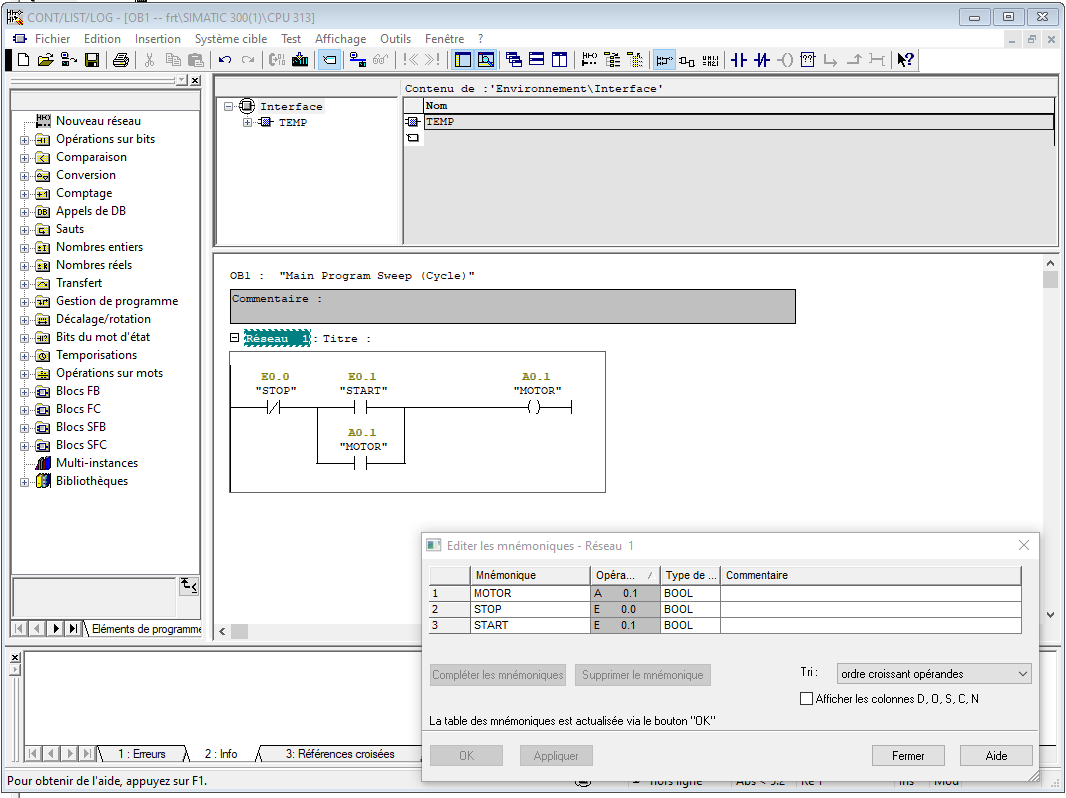
After setting up the program structure, double-click the Symbol Table. A window will open where you can define the names (mnemonics) for the inputs and outputs used in the program.
For example, you can assign descriptive names such as:
START→ Start push buttonSTOP→ Stop push buttonMOTOR→ Motor contactor
This makes the program easier to read and understand instead of working only with absolute addresses.
Personally, I prefer this method because it is a quick and convenient way to define the symbols before starting the Ladder programming.
Save the block, then close the window.
2.4 PLC Simulation
After closing the programming window, go to Options → Set PG/PC Interface.
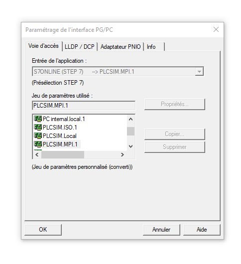
In the Interface Parameter Assignment Used section, select PLCSIM (MPI) as the communication protocol, then click OK.
Next, click the PLCSIM icon to open the simulation window.
Once the simulator is open, press Ctrl + L to load the program.
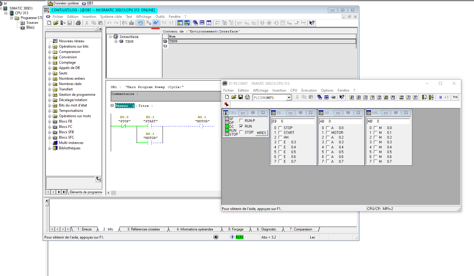
The initial test is now ready. The PLC program has been loaded into the simulator, so the next step is to configure the HMI screen using WinCC Flexible.
4. Creating and Connecting the HMI
Open WinCC Flexible and go to:
Project → New
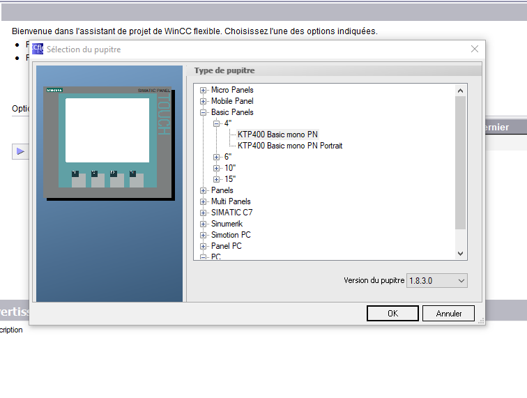
A window will appear asking you to select the HMI device you want to use.
For this project, I will use a Basic Panel ''KTP400 BASIC MONO PN''
After the project finishes loading, go to:
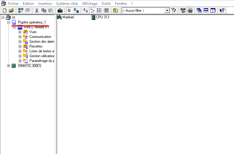
Project → Integrate into STEP 7 Project
Select the location where your STEP 7 project is saved.
WinCC Flexible will then be integrated with the STEP 7 project, allowing the HMI project and the PLC project to work together.
Compatibility Note
If WinCC Flexible and STEP 7 versions are not fully compatible, you may encounter problems during integration.
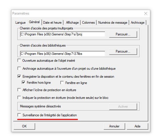
As a precaution, I recommend disabling the Surveillance option in STEP 7 before integrating the HMI project.
You can find this option under:
Options → Customize / Parameters
Once the integration is complete, the WinCC Flexible HMI project is linked to the STEP 7 project, and we can move on to configuring the HMI screen and its communication with the PLC.
5. Connecting the HMI to the PLC
The next step is to establish communication between the HMI and the PLC.
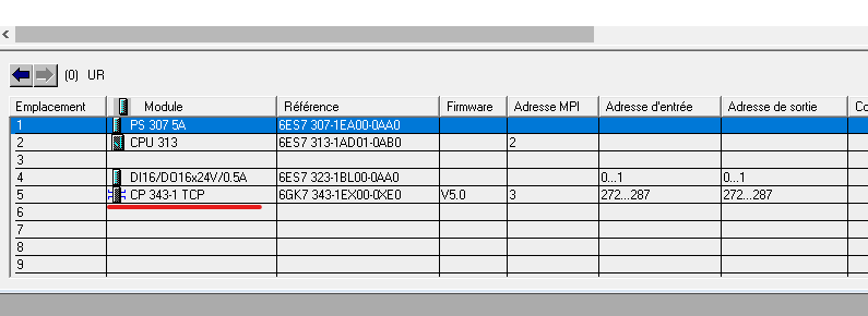
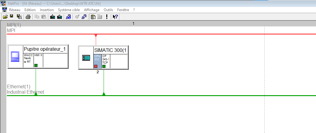
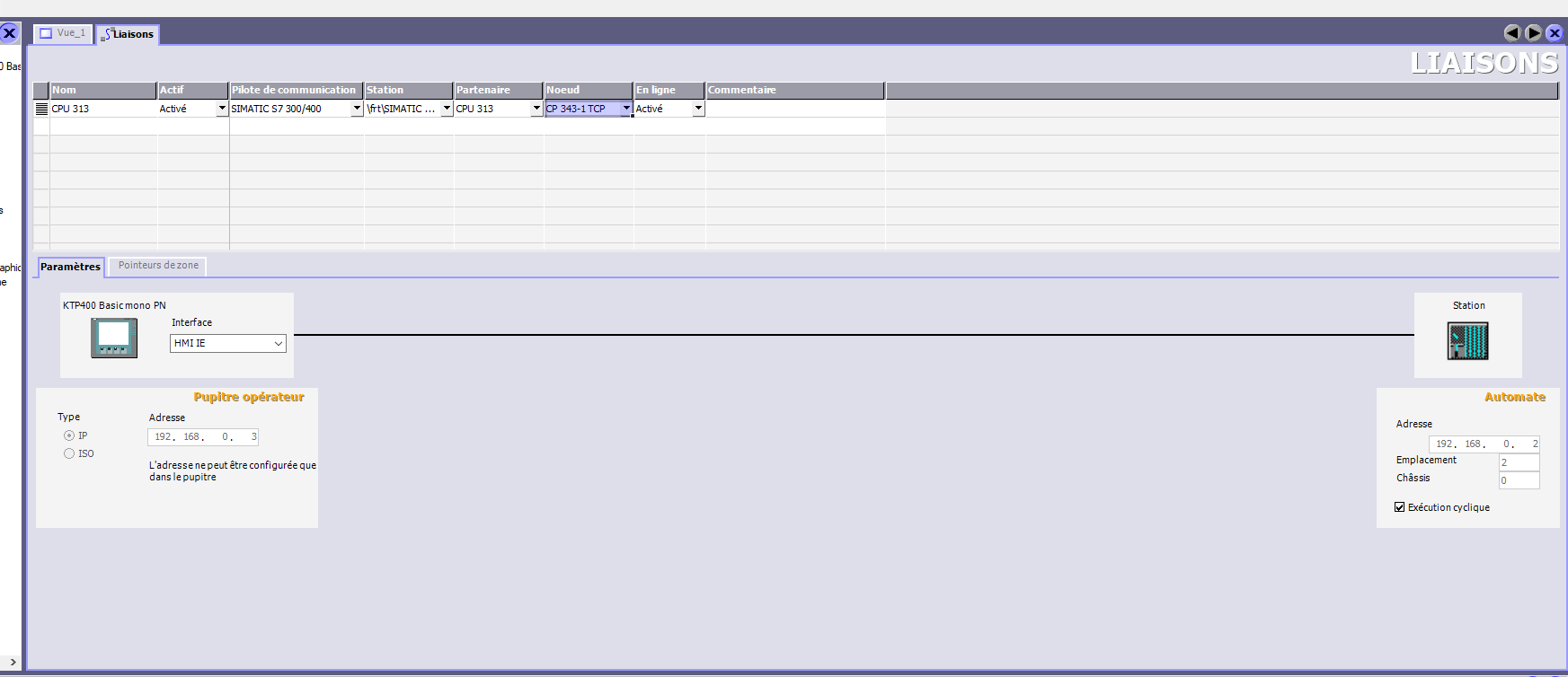
The CPU 313 I selected does not have a built-in PROFINET interface, while the HMI supports PROFINET communication. To solve this, I added a suitable communication module to the PLC to provide the required network interface.
After configuring the communication settings and verifying that the connection between the HMI and PLC is established, I moved on to configuring the HMI variables.
5.1 Creating the HMI Variables
In STEP 7, I created two memory variables (M):
- START 1 — used to start the motor.
- STOP 1 — used to stop the motor.
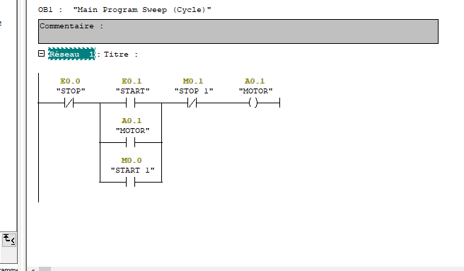
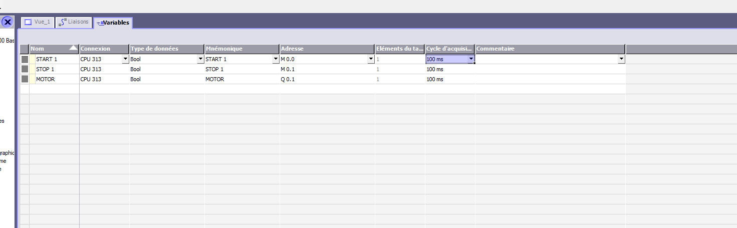
I then linked these variables to the corresponding HMI buttons.
5.2 Designing the HMI Screen
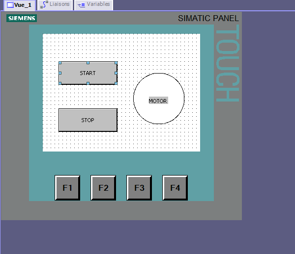
For the HMI screen, I used elements from the WinCC Flexible Library.
I added two buttons from the WinCC Flexible Library and named them START and STOP. I also added a circular indicator to show the motor status.
I then linked the START 1 and STOP 1 memory variables to their respective buttons.
Finally, I linked the MOTOR output variable to the motor status indicator. This allows the indicator to show whether the motor output is ON or OFF.