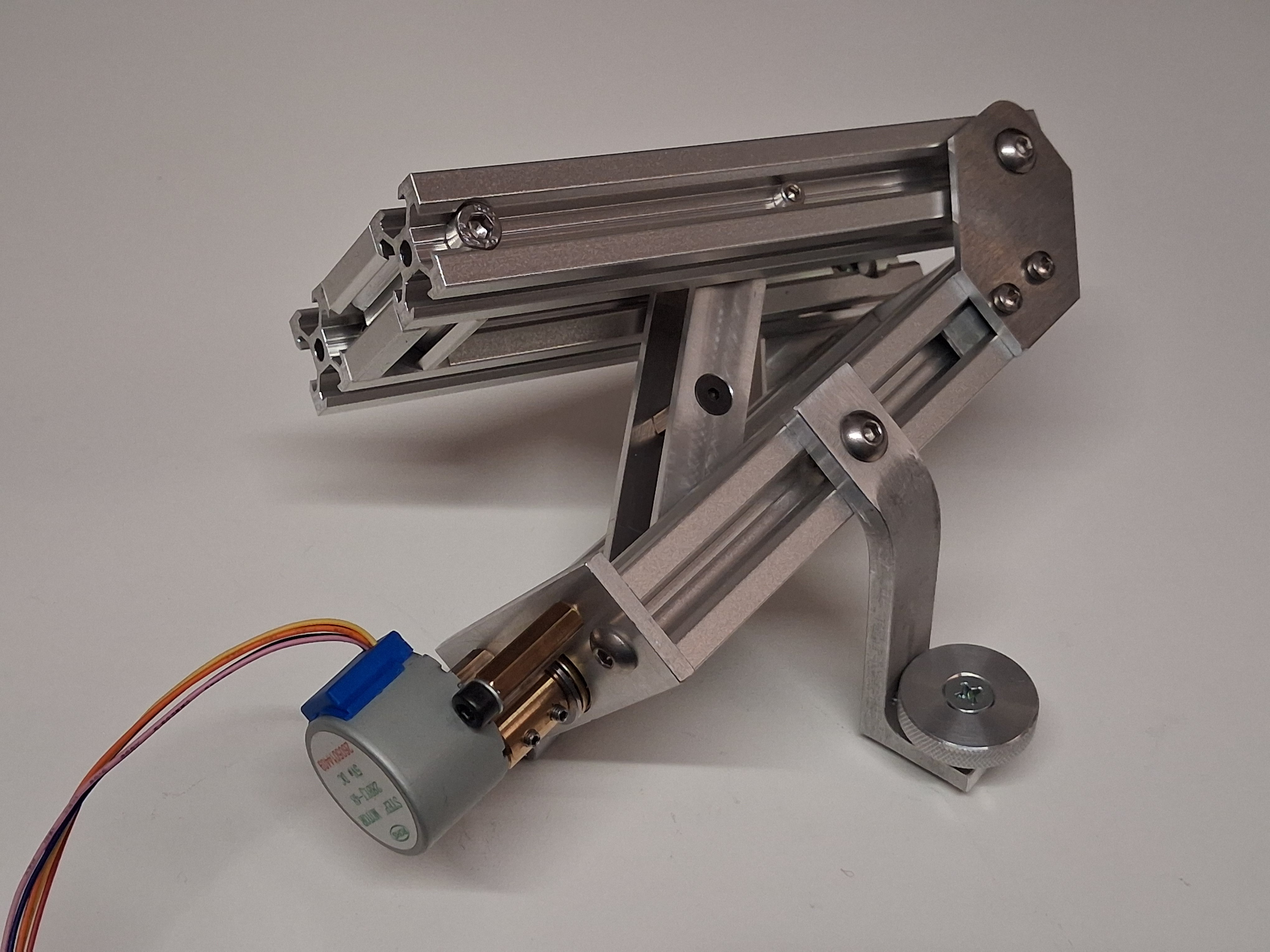
My second barn-door tracker, this time made from metal!
To make the experience fit your profile, pick a username and tell us what interests you.
We found and based on your interests.
The stepper motor runs "open loop" so the controller has no way of knowing the position of angle of the tracker. It keeps track of the step count each time the motor is stepped so, as long as it starts up in a known position, and isn't allowed to stall at all, it all works fine.
The controller also has a 'clock' which counts the milliseconds that have elapsed since powering on. After each step, the controller calculates the exact clock time of the next step. It does this using a bit of maths which relates the step count - and therefore the position of the nut - to the angle of the moving part of the tracker. The angle must increase at a constant rate, but the timing of the steps is changing slightly all the time.
Once the calculated clock time passes, the motor is stepped again and the cycle repeats.
I've been working on this a few weeks, so the design is already quite advanced. Here's what I've got so far:
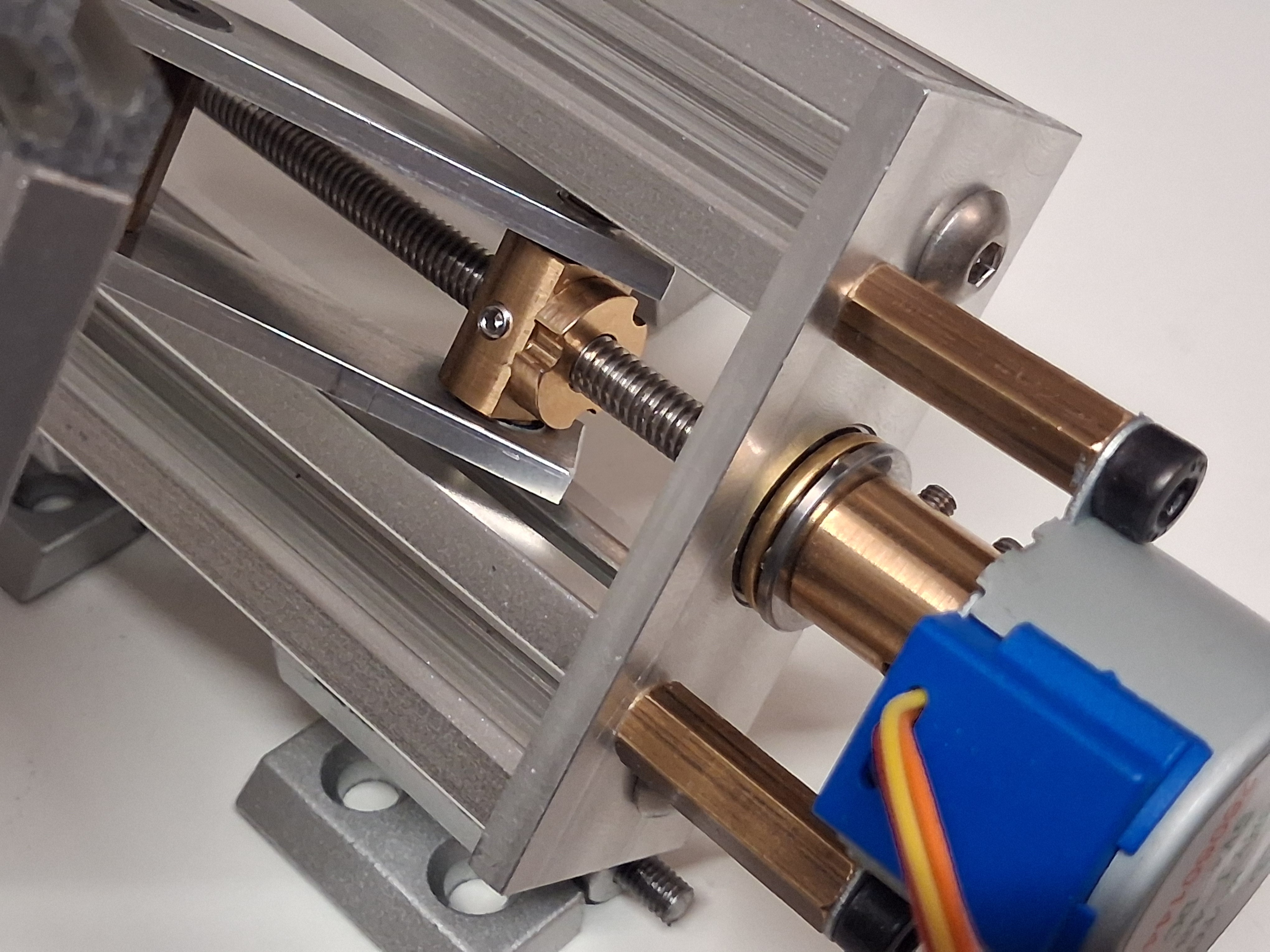
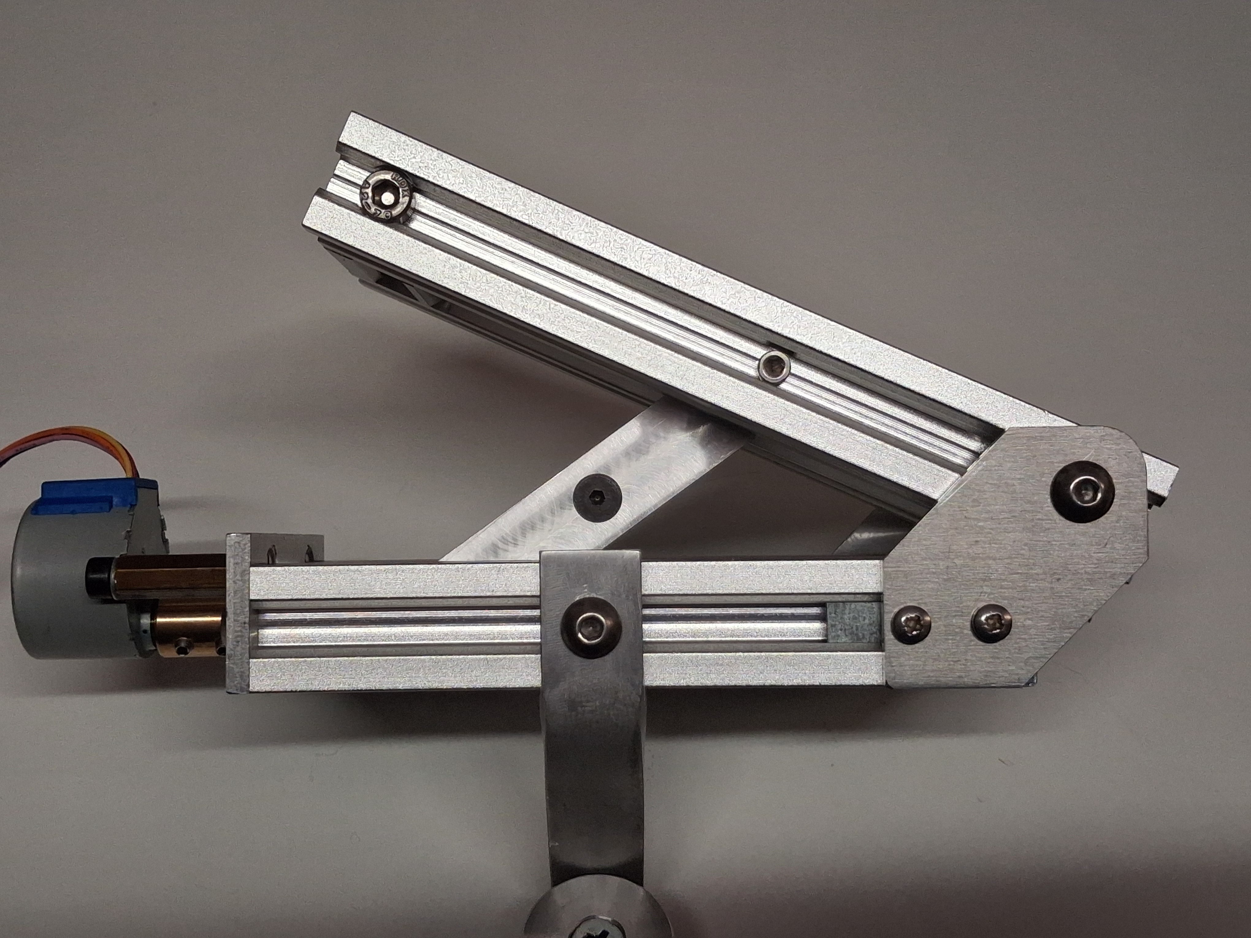
The mechanism is quite different: a nut is driven along a straight, linear leadscrew which in turn opens the two halves via a linkage. Since the opening angle must increase at a constant rate, but the position of the nut along the screw is not proportional to the angle, the screw cannot be driven at a constant rate. Instead a microcontroller (Arduino Nano) is used to calculate the precise moment to step the motor each time (20-30 times per second) in order to compensate for the changing relationship between nut position and opening angle.
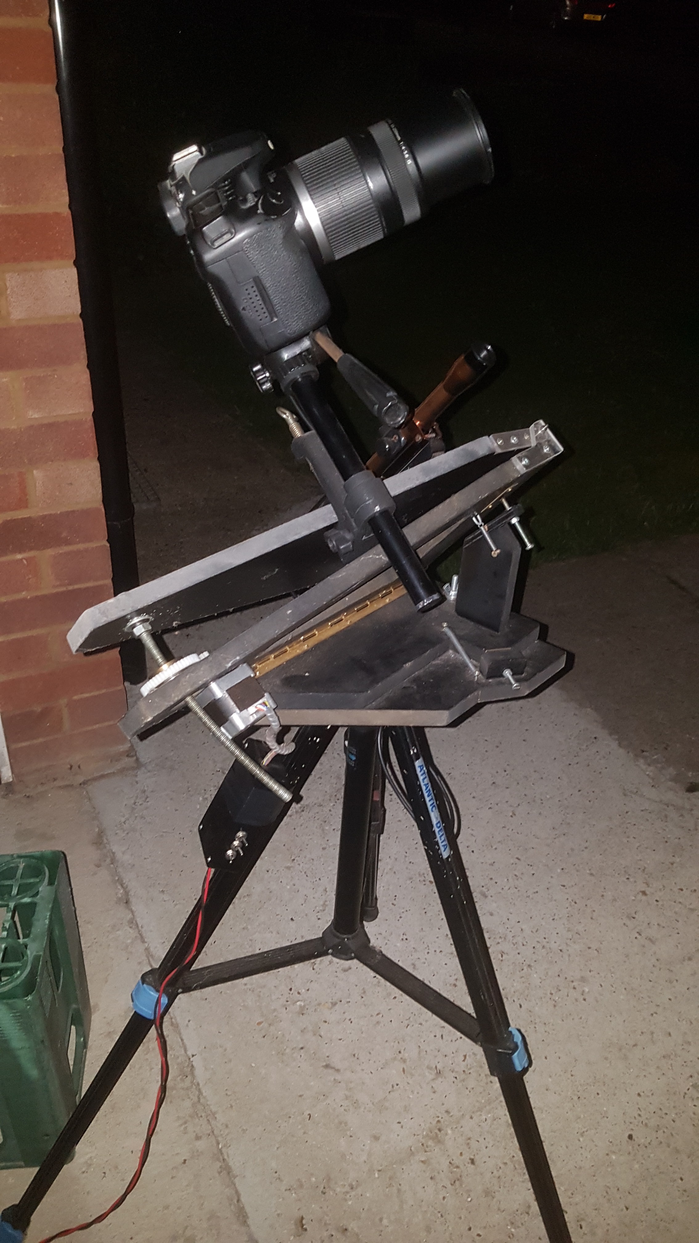
Here's a pic of the original wooden tracker with my DSLR attached:
It uses a stepper motor driven at a fixed 32-steps-per-second rate, courtesy of a 32kHz quartz crystal clock and frequency divider. The motor drives a nut along a curved, threaded rod, which opens the two halves at the required 15degrees-per-hour rate. The down-side is that the curved rod tends to waggle (the thread isn't very accurate) so very long exposure images are a little blurry. Overall accuracy is also limited by poor dimensional tolerance when drilling the holes for the bearings - the whole thing has to be large to minimise the tolerance effects.
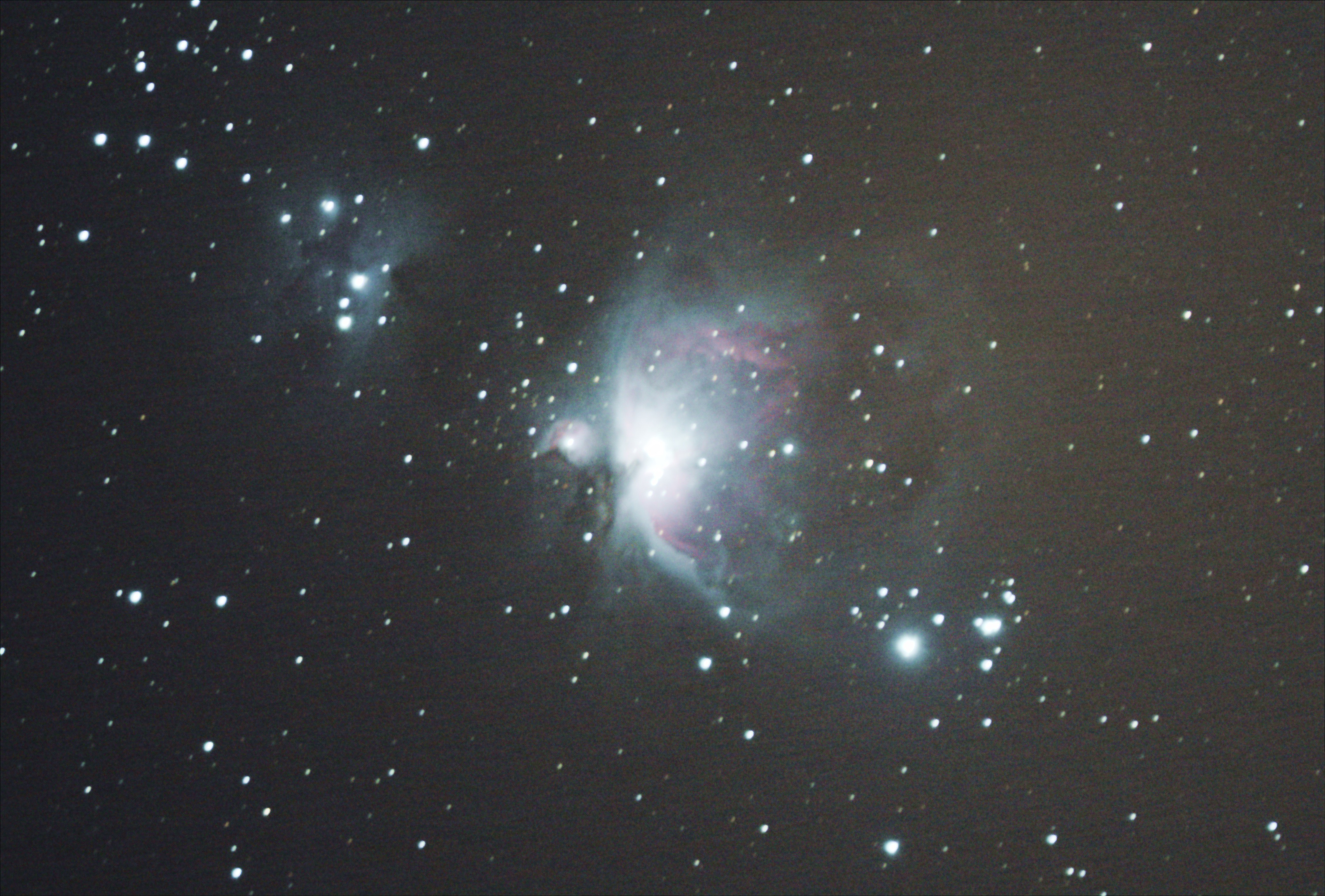
Nevertheless, here's a pic I managed to take by stacking dozens of short(ish) exposures:
This is the benchmark to try and beat!
Create an account to leave a comment. Already have an account? Log In.
Become a member to follow this project and never miss any updates