 vishal soni
The next step is to install the heat-set inserts, which provide strong, durable threads for securing the PCB with screws.
Place a heat-set insert into each hole of the 3D-printed enclosure. Position the tip of your soldering iron on top of the insert and apply gentle, even pressure. As the insert heats up, it will slowly melt into the plastic and sink into its pocket.
Make sure to keep the soldering iron perfectly vertical while inserting it. If you notice the insert starting to tilt, gently adjust it before the plastic cools so that it sits straight and flush with the surface. A properly aligned insert will make it much easier to install the screws later.
Repeat the same process for the second heat-set insert, as shown in the image. Once the plastic has cooled, the inserts will be firmly locked in place, creating strong, reusable threads for the final assembly.
Screw PCB on 3D Print
COMPONENTS:
- RGB Through Hole LED (amazon.com)
- 3P Dip Switch (amazon.com)
- CR2032 SMD HOLDER (amazon.com)
- CR2032 cell (amazon.com)
- 3 X 100 Ohm SMD Resistor (amazon.com)
- Super Glue (amazon.com)
- 2 X M2 3mm heat inserts (amazon.com)
- 2 X M2 4mm Screws (amazon.com)
- Custom PCB
- 3D Printed Parts
TOOLS:
- Soldering Iron (amazon.com / amazon.in)
- Screwdriver (amazon.com / amazon.in)
RGB Through Hole LED
RGB through-hole LEDs are available in two different types: Common Anode and Common Cathode. To make this project as beginner-friendly and flexible as possible, I designed the PCB with selectable solder jumpers that support both types of RGB LEDs. This means you don't have to worry about buying a specific version. Simply purchase whichever RGB LED is available in your local market or online store, set the appropriate jumper on the PCB, and you're ready to go. This small feature makes the Aurora Pendant more versatile and ensures that the project can be built easily using commonly available components.
3P Dip Switch
A 3P DIP switch (3-position Dual In-line Package switch) is a simple manual switch that is mounted directly on the PCB. It contains three independent ON/OFF switches, each controlling one channel of the RGB LED. In the Aurora Pendant, each switch controls one color—Red, Green, or Blue. By turning the switches on and off in different combinations, you can create 7 different color combinations (excluding the all-off state). This allows you to easily change the pendant's color without any programming, microcontroller, or mobile app.
CR2032
The CR2032 is one of the most popular 3V lithium coin cell batteries used in compact electronic devices. It measures 20 mm in diameter and 3.2 mm in thickness, while offering a typical capacity of 220–240 mAh. For the Aurora Pendant, the CR2032 is an ideal power source because it is small, lightweight, inexpensive, and readily available. It provides enough power to drive the RGB LED while keeping the pendant compact and wearable. You can easily find CR2032 batteries in local electronics stores or online, as they are commonly used in car key fobs, wristwatches, calculators, computer motherboard CMOS backup, and many other portable electronic devices. When the battery is depleted, it can be replaced in just a few seconds, allowing the pendant to be used again without any special tools.
Designing the Pendant in Tinkercad
Hi,
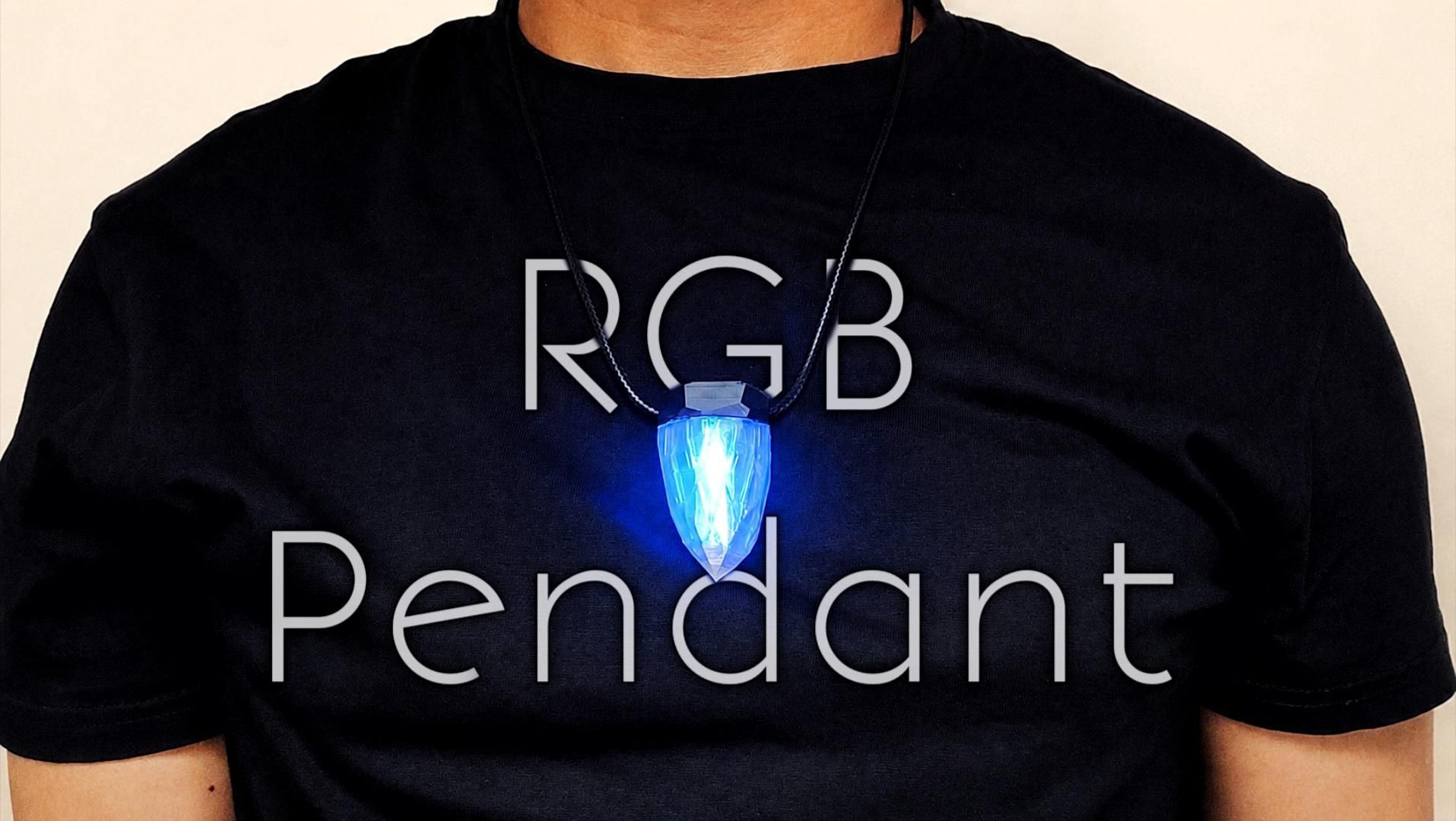
One day, my girlfriend and I were getting ready to attend an event, but we were running late. While I was ready to leave, she was still searching through her jewelry. When I asked what was wrong, she smiled and said, "I can't find a necklace that matches my dress."
That simple moment sparked an idea in my mind: Why not make a pendant that can change its color to match any outfit?
And that's how I created the Aurora Pendant. The name "Aurora" is inspired by the beautiful Aurora Borealis, the natural light display created when charged particles from the Sun collide with gases in Earth's atmosphere. Just like the colorful lights dancing across the night sky, this pendant can glow in multiple colors, making it a perfect name for the project.
My goal was to make this pendant as simple as possible, so that even beginners and kids with basic soldering skills could build it. Instead of using a programmable microcontroller, I designed it to be non-programmable and powered by a coin cell battery, making the circuit inexpensive, reliable, and easy to assemble.
Buy This 🛒: Link
By the way, Subscribe to my YouTube channel for more projects like this. I also update my upcoming projects on Instagram.
buy me a coffee! ☕: Donate
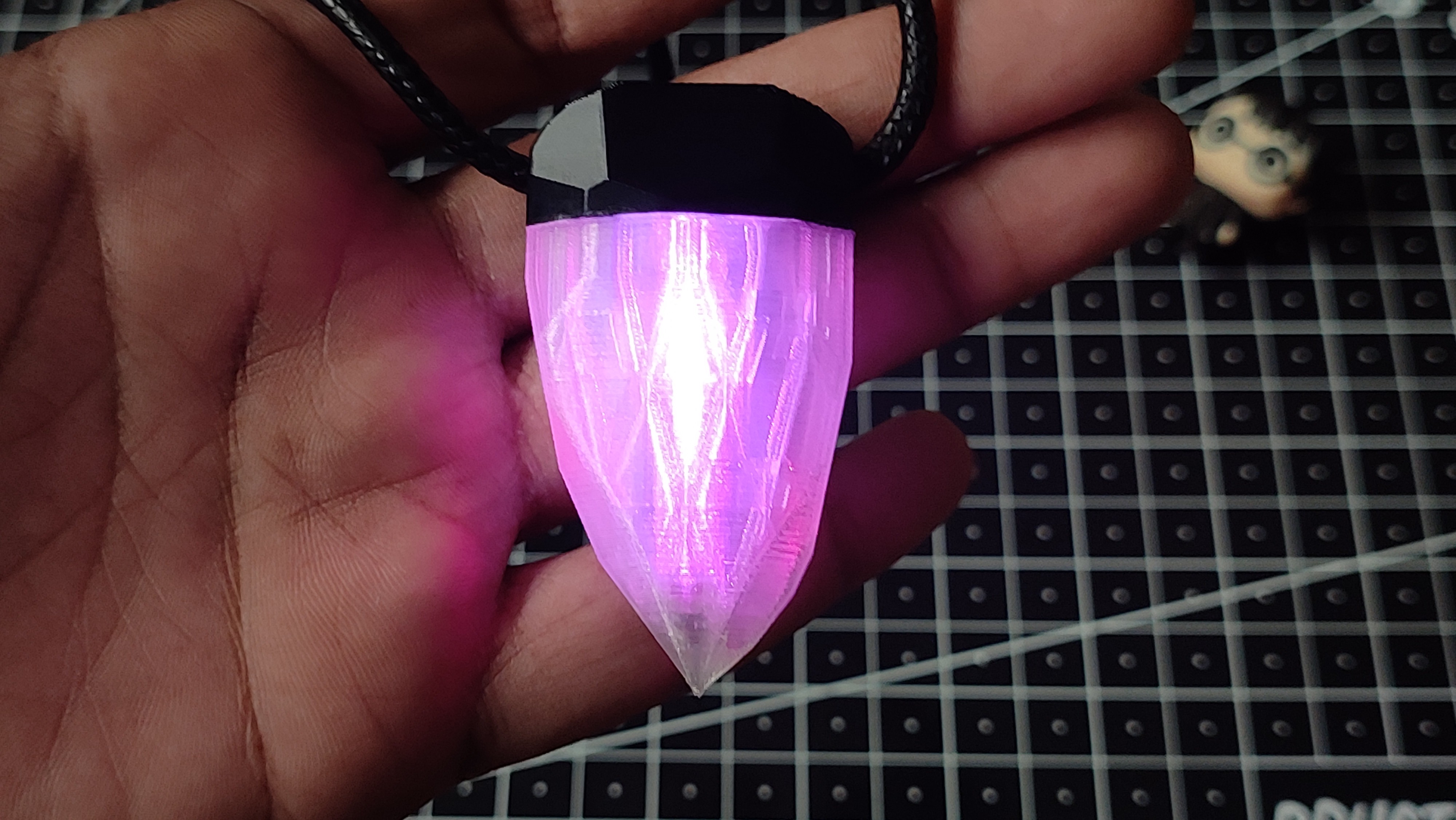
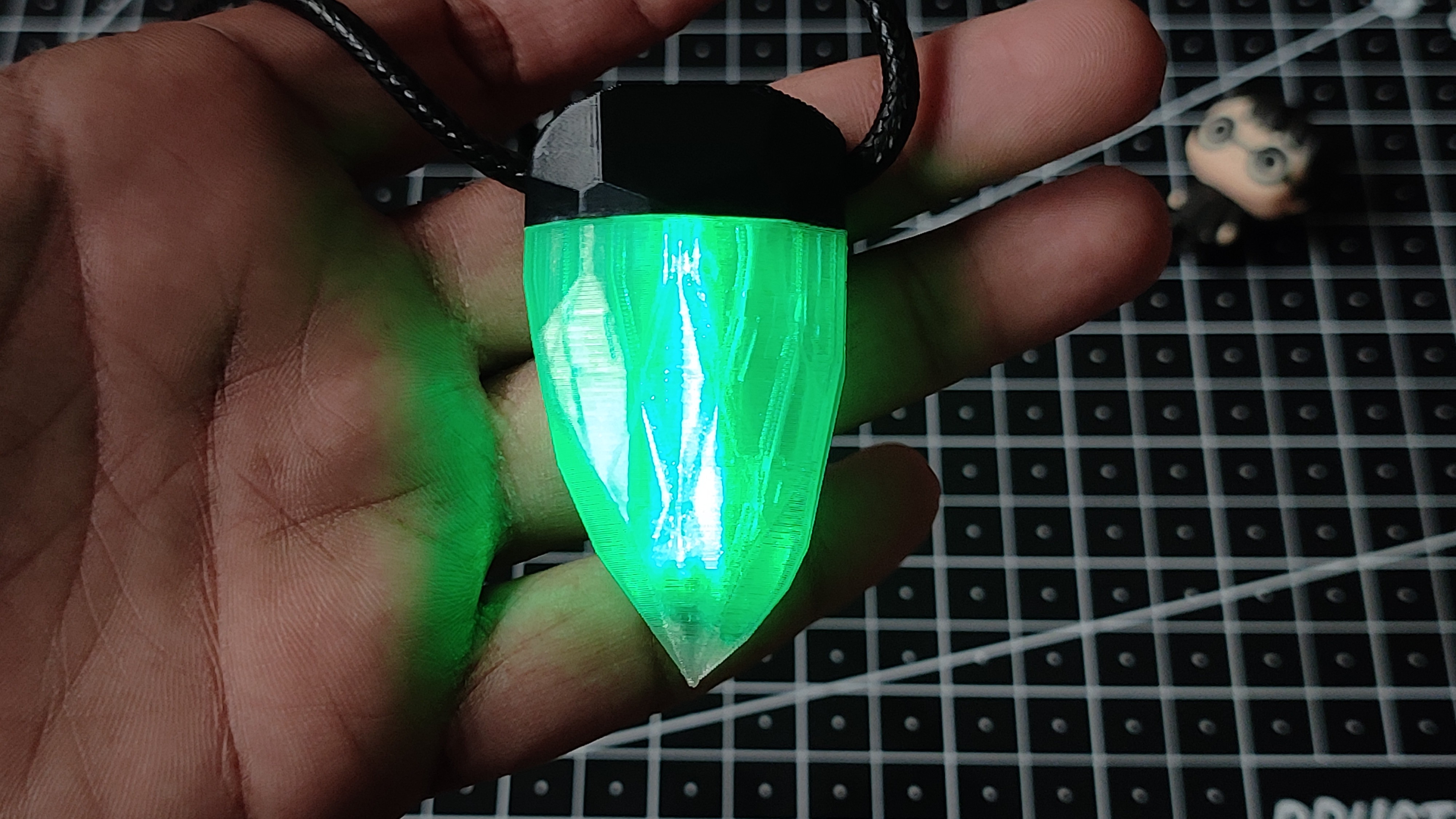
The pendant features three individual switches, each controlling one color of the RGB LED—Red, Green, and Blue. By turning the switches on and off in different combinations, you can create 7 unique colors, allowing the pendant to match different outfits, occasions, or moods.
To complete the project, I designed two different 3D-printed enclosures. One is printed in solid white, while the other is made from semi-transparent material that diffuses the LED light for a softer glow. Since I couldn't decide which one looked better, I built both versions.
So, let's build the Aurora Pendant together and find out which design shines the brightest!
Supplies
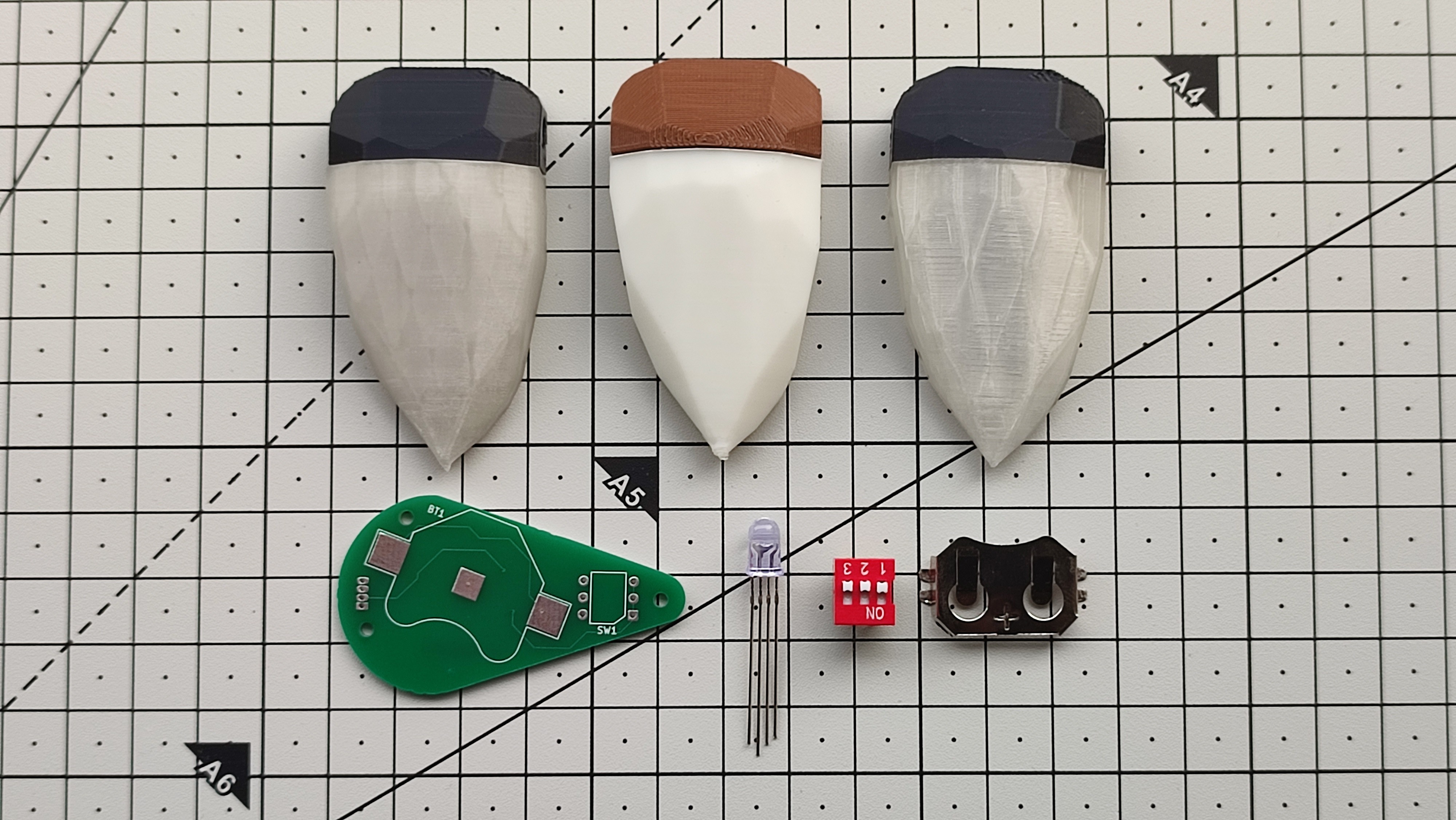
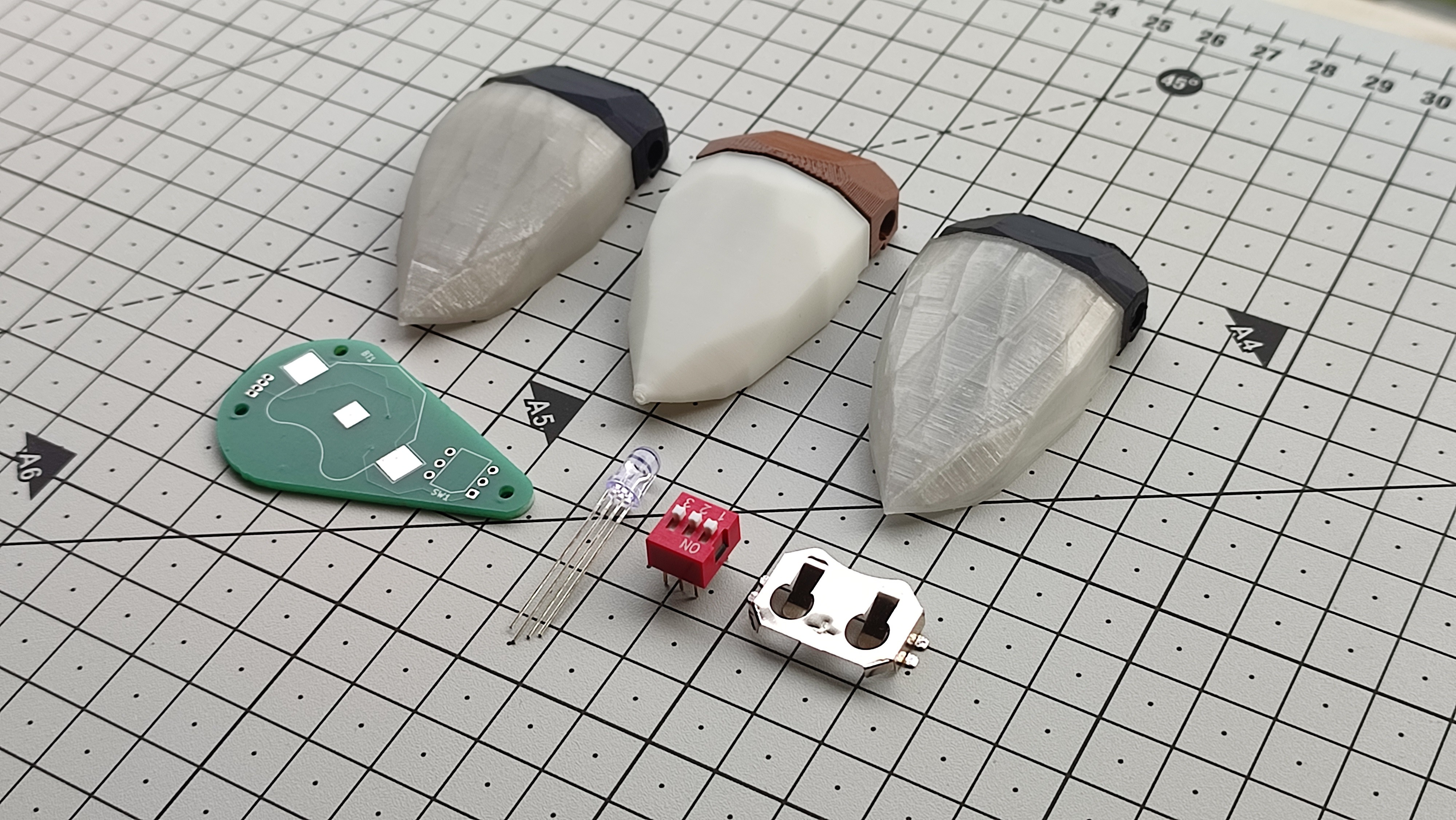
COMPONENTS:
- RGB Through Hole LED (amazon.com)
- 3P Dip Switch (amazon.com)
- CR2032 SMD HOLDER (amazon.com)
- CR2032 cell (amazon.com)
- 3 X 100 Ohm SMD Resistor (amazon.com)
- Super Glue (amazon.com)
- 2 X M2 3mm heat inserts (amazon.com)
- 2 X M2 4mm Screws (amazon.com)
- Custom PCB
- 3D Printed Parts
TOOLS:
- Soldering Iron (amazon.com / amazon.in)
- Screwdriver (amazon.com / amazon.in)
RGB Through Hole LED
RGB through-hole LEDs are available in two different types: Common Anode and Common Cathode. To make this project as beginner-friendly and flexible as possible, I designed the PCB with selectable solder jumpers that support both types of RGB LEDs. This means you don't have to worry about buying a specific version. Simply purchase whichever RGB LED is available in your local market or online store, set the appropriate jumper on the PCB, and you're ready to go. This small feature makes the Aurora Pendant more versatile and ensures that the project can be built easily using commonly available components.
3P Dip Switch
A 3P DIP switch (3-position Dual In-line Package switch) is a simple manual switch that is mounted directly on the PCB. It contains three independent ON/OFF switches, each controlling one channel of the RGB LED. In the Aurora Pendant, each switch controls one color—Red, Green, or Blue. By turning the switches on and off in different combinations, you can create 7 different color combinations (excluding the all-off state). This allows you to easily change the pendant's color without any programming, microcontroller, or mobile app.
CR2032
The CR2032 is one of the most popular 3V lithium coin cell batteries used in compact electronic devices. It measures 20 mm in diameter and 3.2 mm in thickness, while offering a typical capacity of 220–240 mAh. For the Aurora Pendant, the CR2032 is an ideal power source because it is small, lightweight, inexpensive, and readily available. It provides enough power to drive the RGB LED while keeping the pendant compact and wearable. You can easily find CR2032 batteries in local electronics stores or online, as they are commonly used in car key fobs, wristwatches, calculators, computer motherboard CMOS backup, and many other portable electronic devices. When the battery is depleted, it can be replaced in just a few seconds, allowing the pendant to be used again without any special tools.
Designing the Pendant in Tinkercad
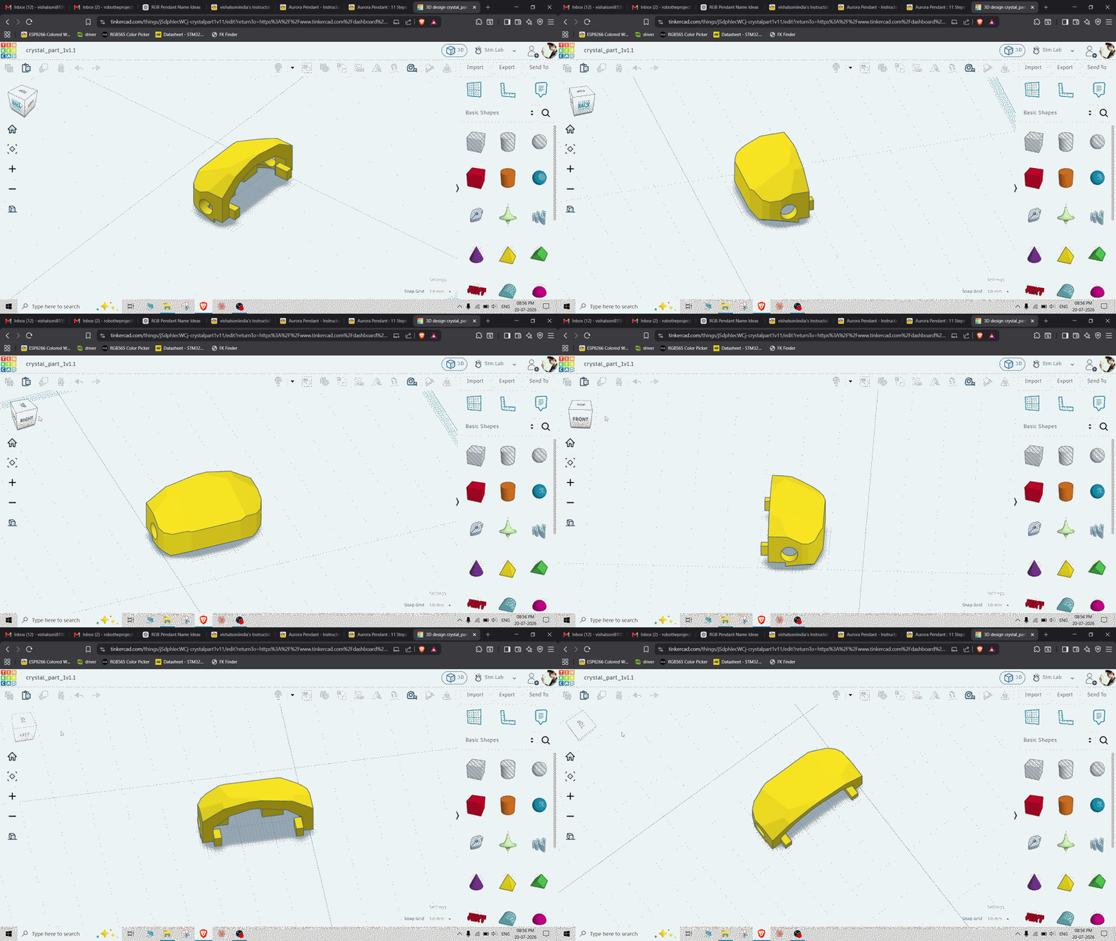
I designed the 3D enclosure for the Aurora Pendant using Tinkercad, a free, browser-based 3D design tool that is perfect for beginners. Its simple drag-and-drop interface makes it easy to create functional designs without any prior CAD experience, making it an excellent choice for makers and hobbyists.
The enclosure is designed in two separate parts, giving the pendant a cleaner and more premium appearance while making assembly straightforward. I chose a crystal-inspired shape so the finished pendant looks more like a piece of jewelry rather than an electronic gadget.
The upper part includes a small hole for attaching a string, chain, or necklace so the pendant can be comfortably worn. Inside the enclosure, I added dedicated mounting points for heat-set inserts, allowing the PCB to be securely fastened with screws. This not only keeps the electronics firmly in place but also makes the pendant easy to disassemble for battery replacement or future modifications.
3D Printing the Enclosure
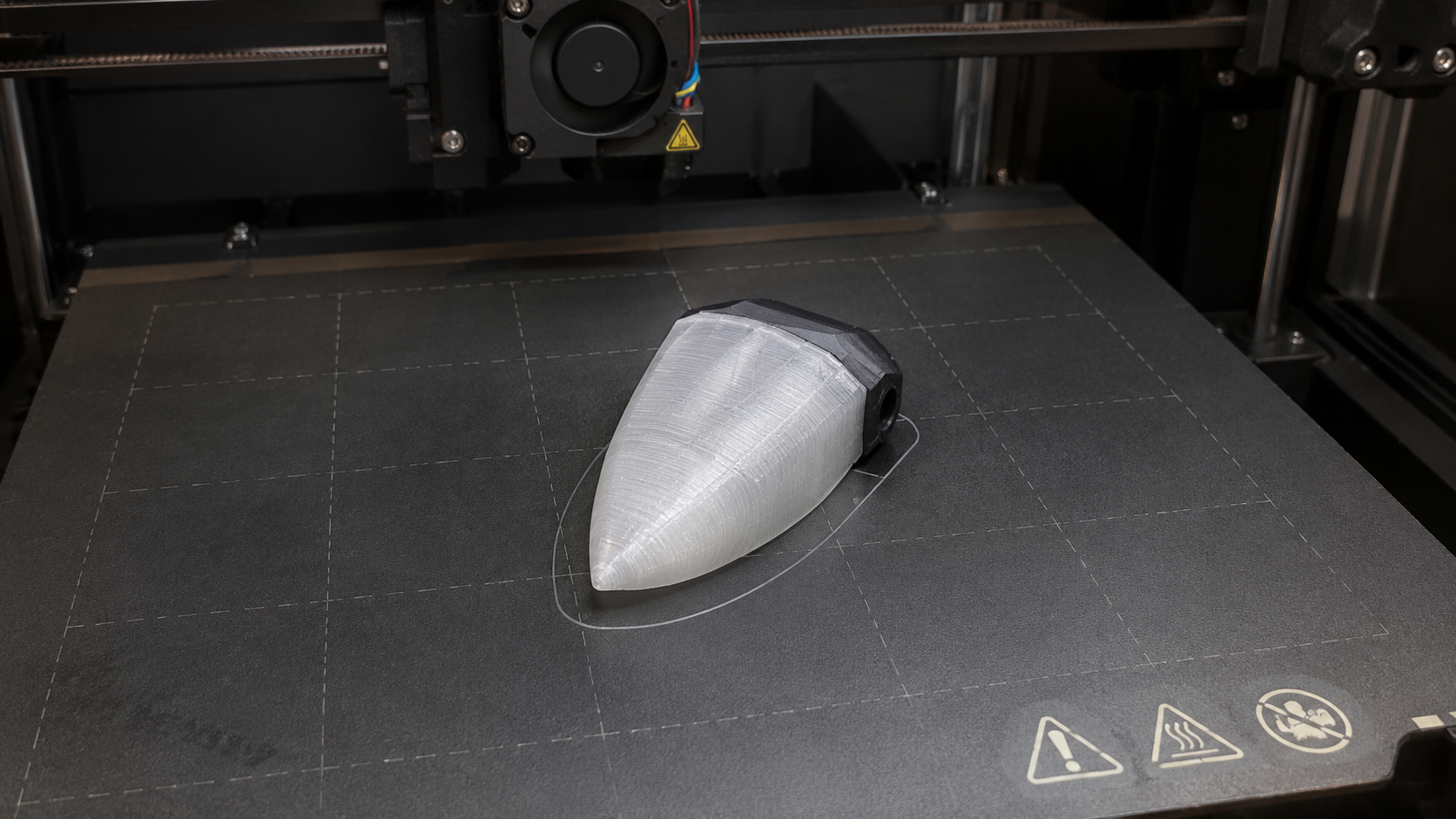
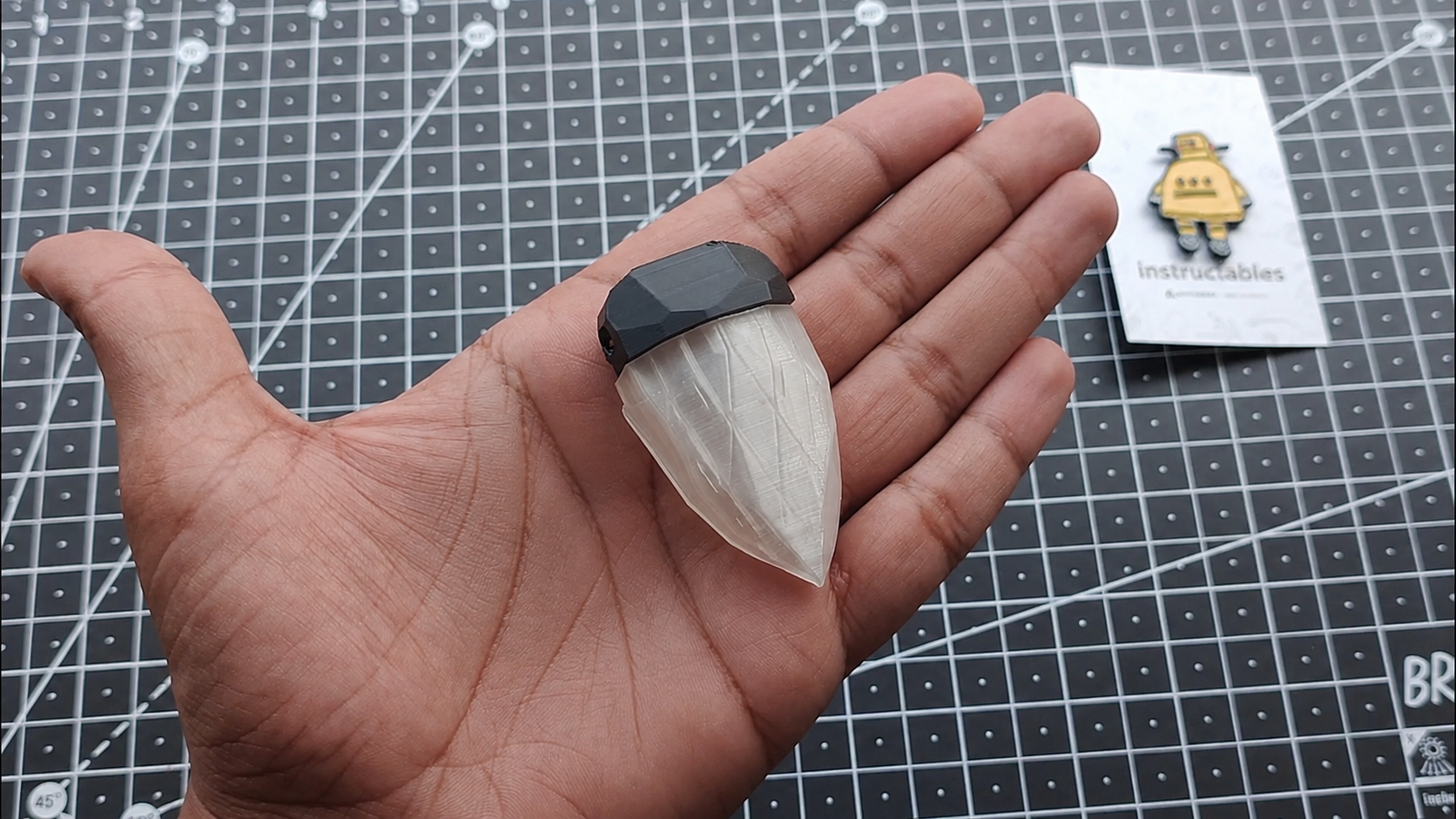
Printing Details:
- Nozzle: 0.1 mm (for fine detail and smooth finish)
- Infill: 20>#/b### (strong yet lightweight)
- Material: ABS – Black (durable, heat-resistant, and gives a professional look)
To see how the enclosure would affect the appearance of the pendant, I 3D printed it in two different materials. One version was printed in solid white PLA, while the other was printed in semi-transparent PLA to experiment with light diffusion.
The white enclosure gives the pendant a clean, modern look and hides the internal electronics completely. In contrast, the semi-transparent enclosure allows the RGB LED light to spread more evenly throughout the body of the pendant, creating a softer, crystal-like glow.
Printing both versions was a fun experiment that helped me compare their overall aesthetics, brightness, and light diffusion. You can choose the version you like best—or print both and decide for yourself!
PCB Design
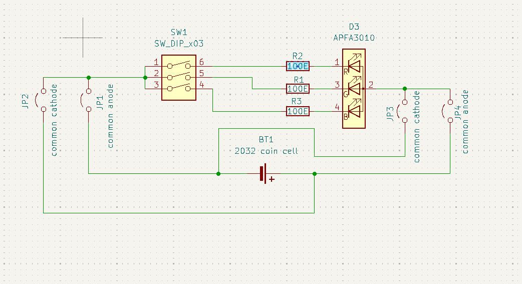
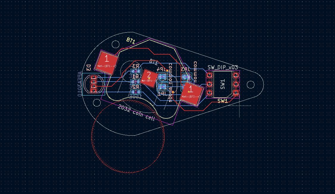
I designed the PCB for the Aurora Pendant using KiCad, a powerful and free open-source PCB design software. I started by creating the schematic, where I connected all the electronic components and verified that the circuit functioned correctly. Once the schematic was complete, I assigned the appropriate footprints to every component before moving on to the PCB layout.
One feature I really like about KiCad is its 3D modeling support. I imported the 3D models of the major components, which allowed me to visualize the completed PCB and ensured that everything would fit perfectly inside the 3D-printed enclosure. This made designing the enclosure much easier and helped avoid mechanical fitting issues before manufacturing the PCB.
To make the project as flexible as possible, I also added two solder jumpers for Common Anode LEDs and two solder jumpers for Common Cathode LEDs. By simply bridging the appropriate jumpers, builders can use either type of RGB through-hole LED, depending on what is available in their local market. This small addition makes the PCB more versatile and beginner-friendly, eliminating the need to search for a specific LED type.
GitHub : https://github.com/vishalsoniindia/RGB_Pendant
Dip Switch & Resistor Soldering
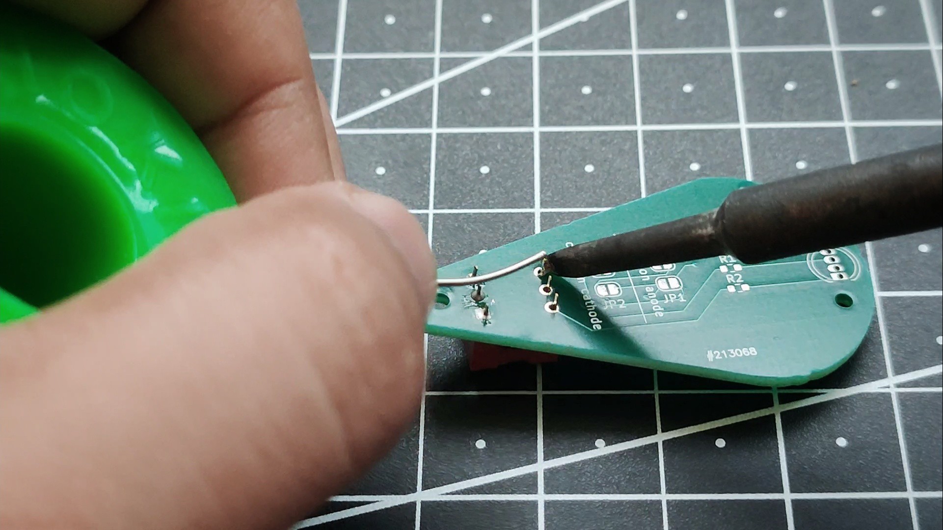
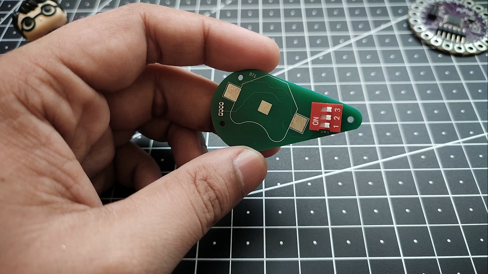
We'll begin by soldering the 3-position DIP switch. Insert the switch into the PCB as shown in the image, making sure it is oriented correctly. Pay close attention to the "ON" marking on the switch, as it should face the correct direction according to the PCB silkscreen. Once the switch is properly seated, flip the PCB over and solder all six pins, ensuring each joint is clean and shiny.
Next, solder the three 100 Ω resistors onto their respective resistor pads. These resistors limit the current flowing through the Red, Green, and Blue channels of the RGB LED, helping to protect the LED while providing balanced brightness.
If you find that the LED is too bright or too dim, feel free to experiment with different resistor values. Lower resistance will increase the LED brightness (while drawing more current), whereas higher resistance will reduce the brightness and extend the battery life. This gives you the flexibility to customize the pendant's appearance to your preference.
RGB LED Soldering
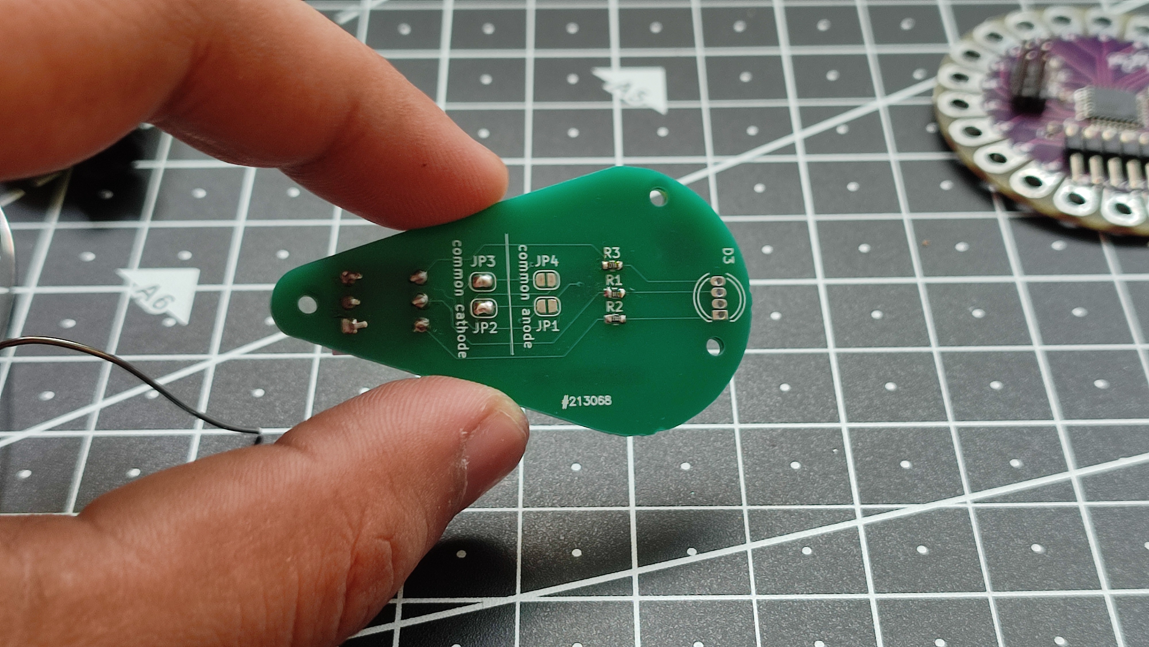
Before soldering the RGB LED, you must first solder the appropriate LED jumper pads on the PCB. Since I am using a Common Cathode RGB LED, I bridged the two Common Cathode jumpers, as shown in the image. If you are using a Common Anode RGB LED, simply solder the Common Anode jumpers instead. Selecting the correct jumpers is essential for the LED to operate properly.
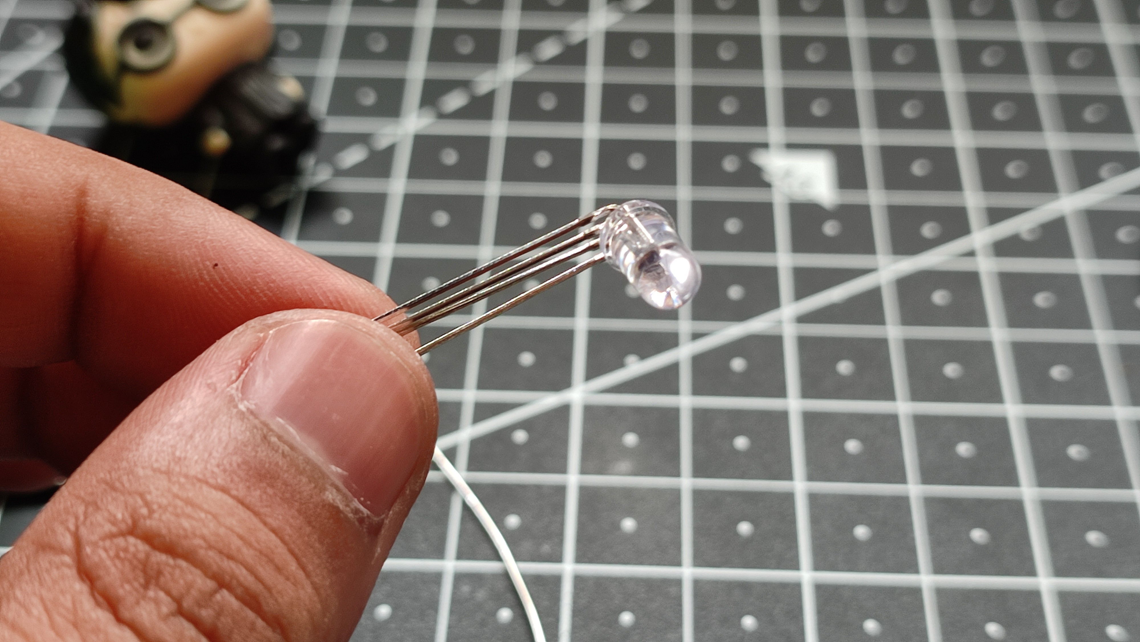
Next, prepare the RGB LED by carefully bending all four leads to a 90° angle, as shown in the image. This allows the LED to sit horizontally inside the pendant enclosure.
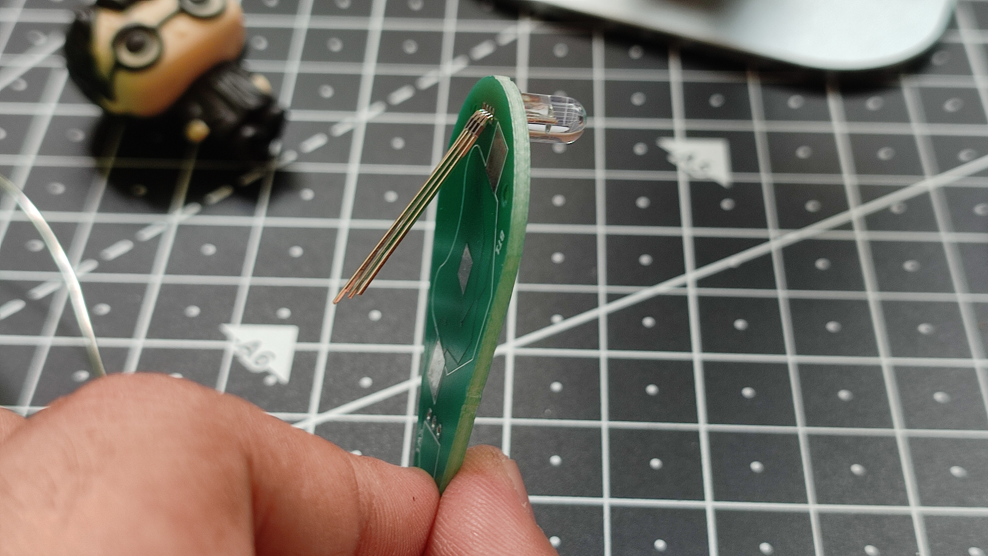
Insert the LED into the PCB with the LED dome facing downward, exactly as shown in the reference image. Double-check that the pins are aligned with the correct holes before soldering.
Once the LED is positioned correctly, solder each of the four leads one by one, making sure every solder joint is neat and secure. After all the connections are complete, use a flush cutter to trim the excess leads from the back of the PCB, leaving a clean and professional finish.
Cell Holder Soldering
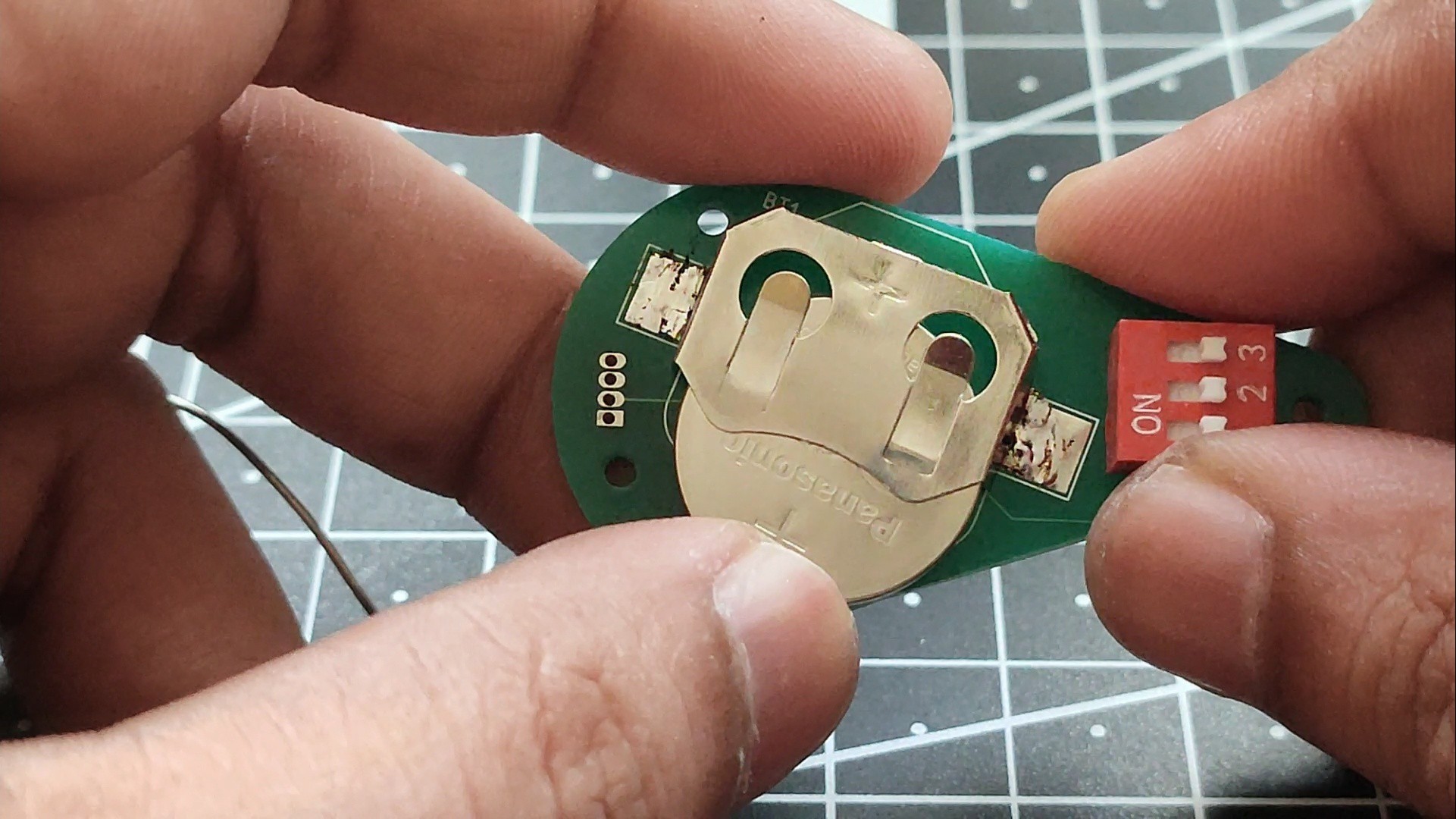
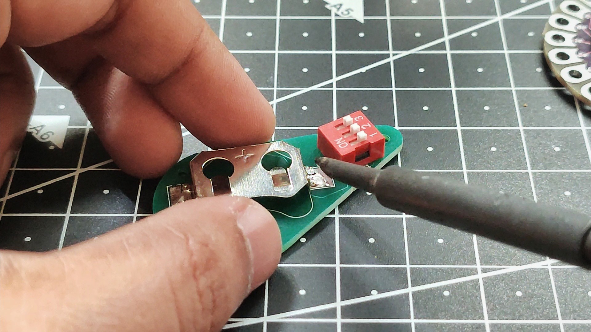
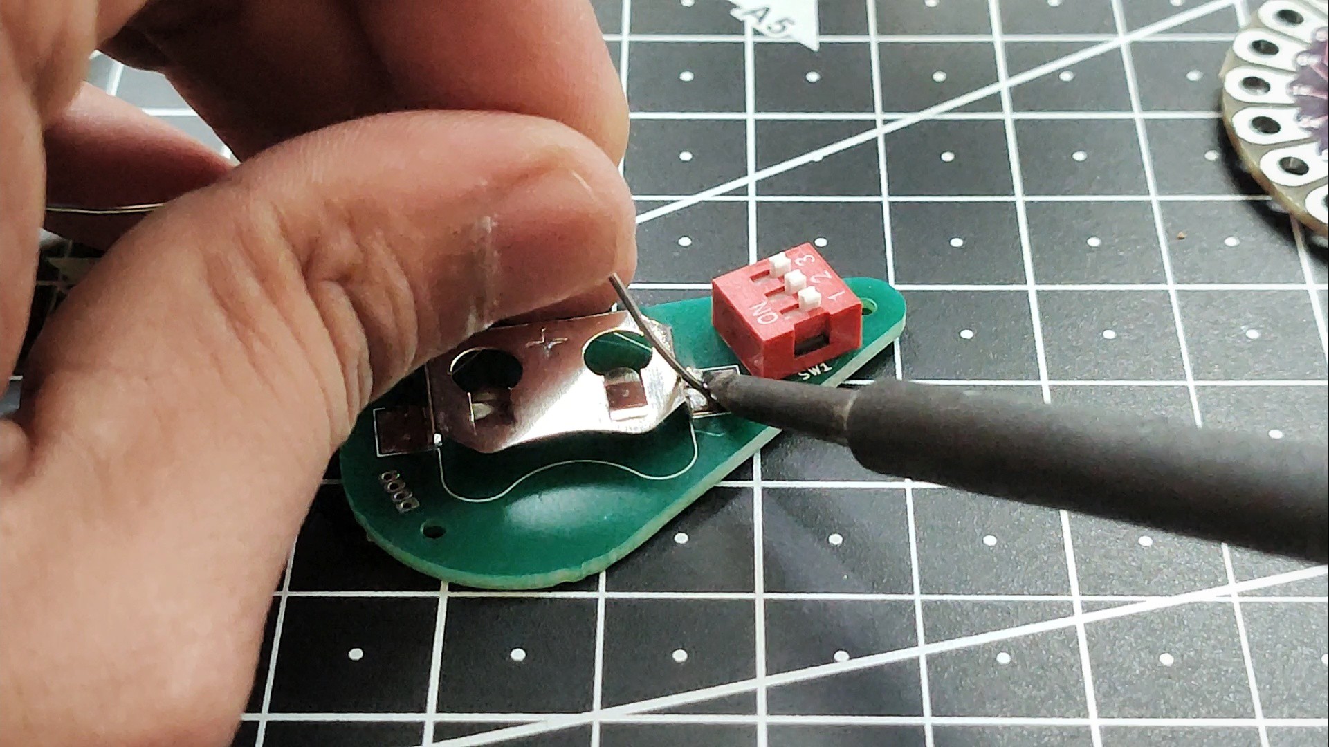
The final component to solder is the CR2032 battery holder. Place the holder onto the PCB, making sure it is aligned correctly with the footprint and sits flat against the board.
To keep it securely in place, solder one of the mounting legs first. This will hold the battery holder firmly while you check its alignment. If necessary, reheat the solder joint and adjust the position before soldering the second mounting leg.
Once the holder is properly aligned, complete the remaining solder joints. Since the battery holder has large metal tabs, they can absorb a lot of heat, so you may need to keep the soldering iron on the joint a little longer than usual. Be careful, as the metal tabs can become very hot during soldering.
After all the joints are soldered, inspect them to ensure they are smooth, shiny, and securely attached. Your PCB is now fully assembled and ready for the battery and enclosure.
Glue 3D Printed Parts
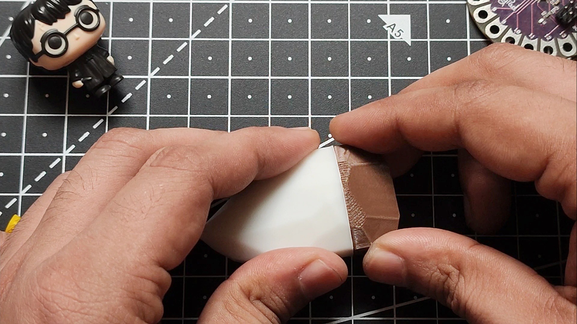
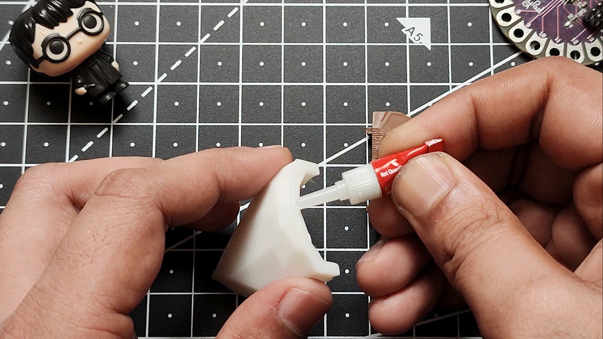
Now it's time to join the two 3D-printed enclosure parts. Apply a small amount of super glue along the joining edge of the bottom part. Be careful not to use too much glue, as excess adhesive may squeeze out and affect the appearance of the pendant.
Carefully align the top part with the bottom enclosure and press the two pieces together. Make sure all the edges line up properly before the glue begins to set.
Hold the enclosure firmly for 20–30 seconds, or according to the curing time recommended for your super glue, to ensure a strong bond. Once the glue has cured, the enclosure will form a sturdy, crystal-shaped pendant ready for the final assembly.
Heat Inserts
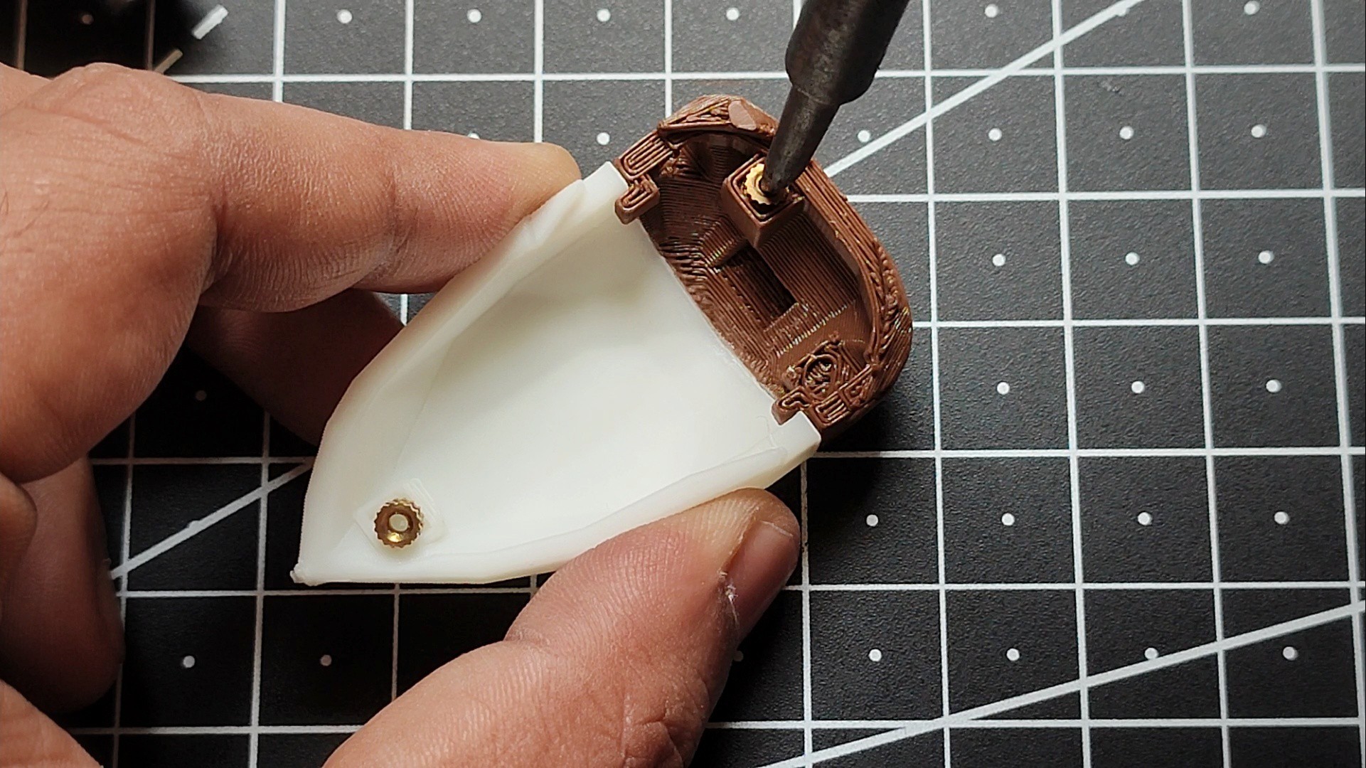
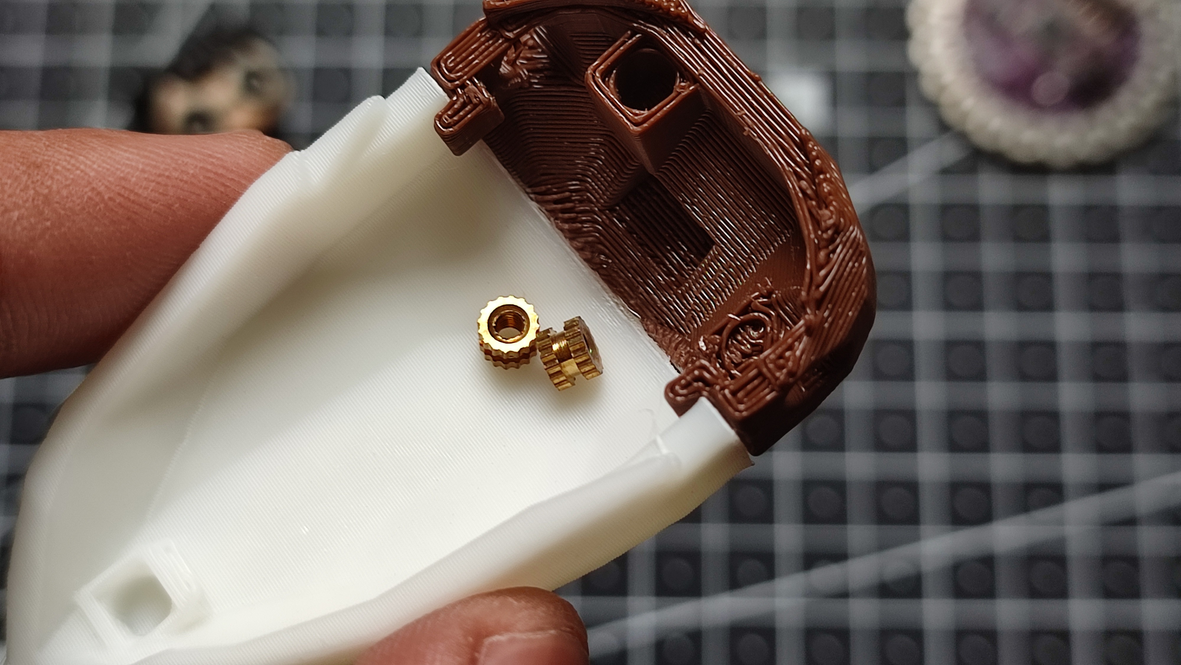
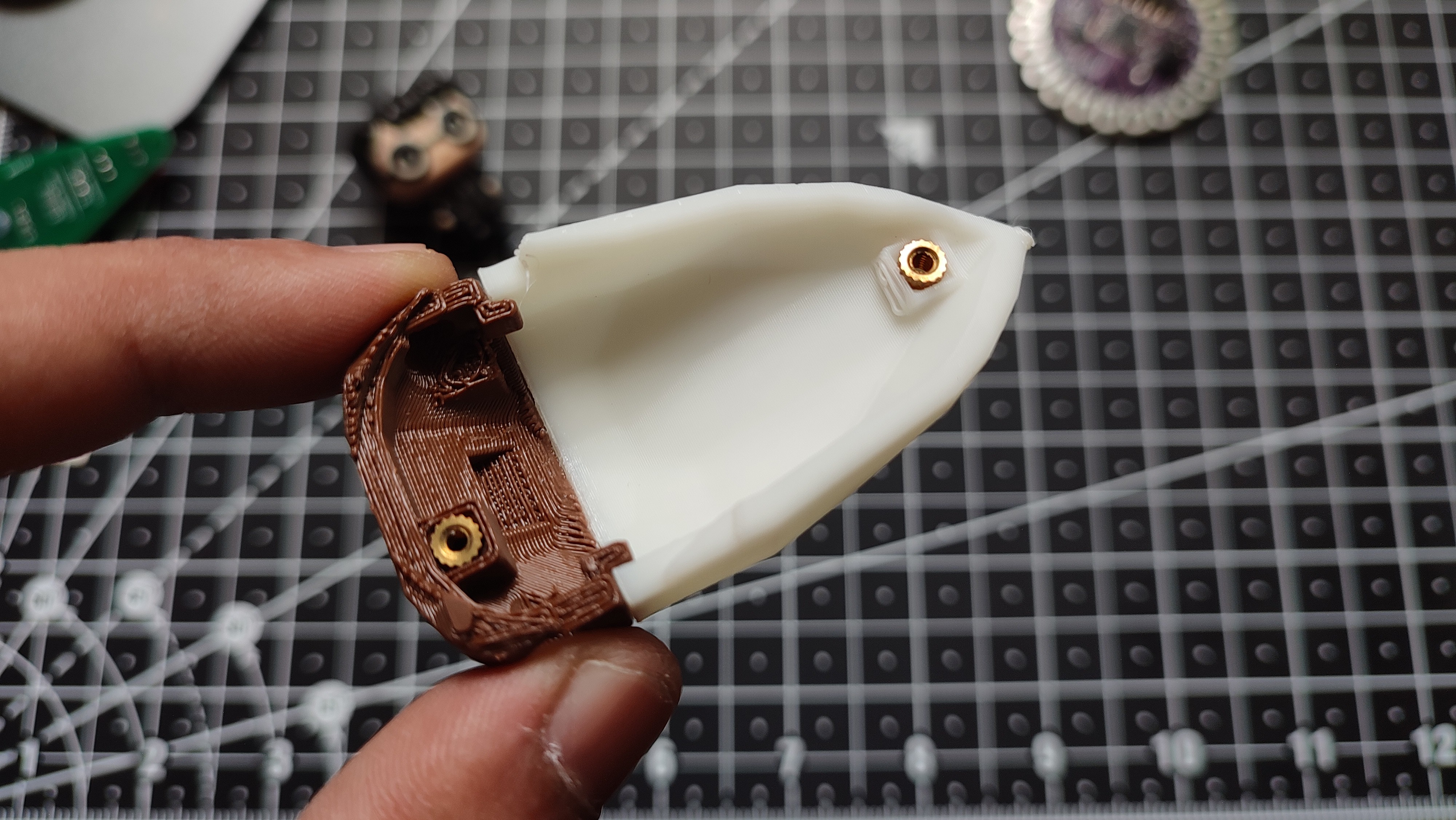
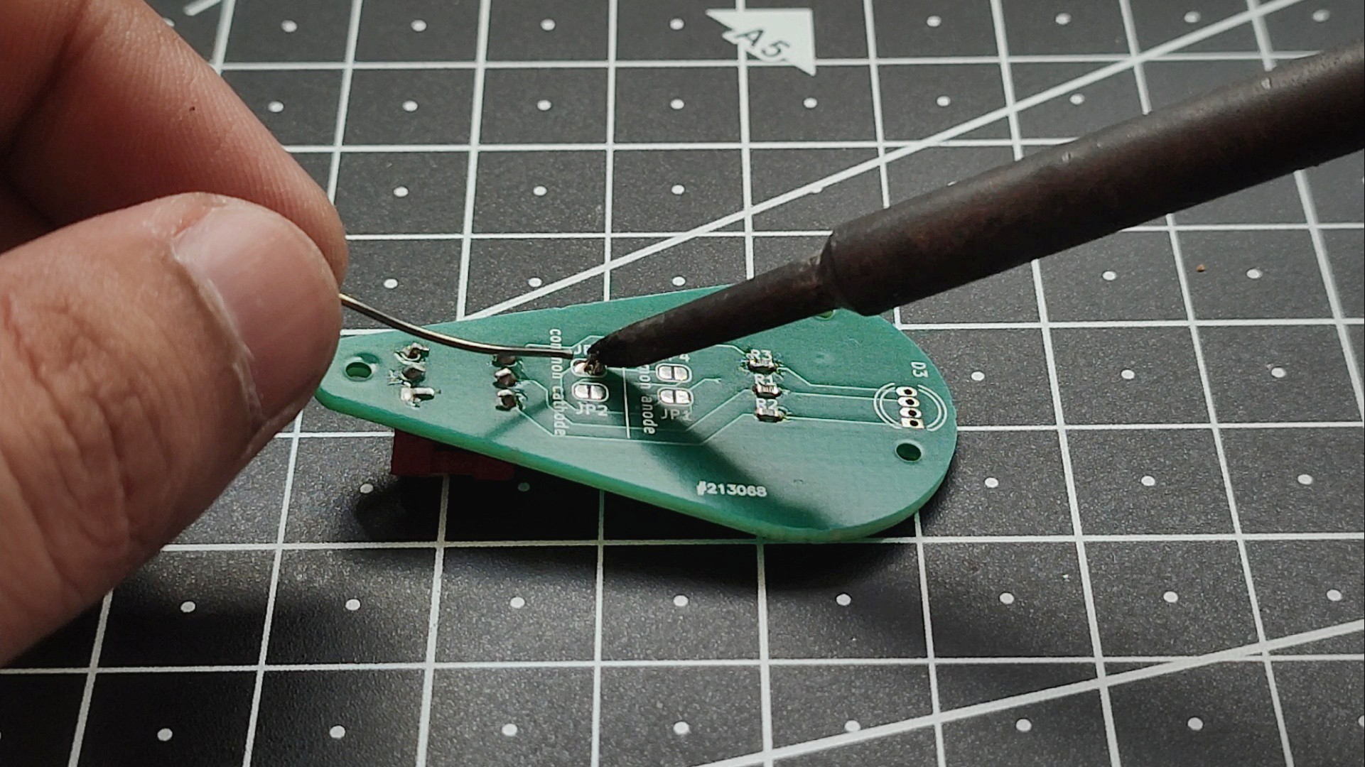
The next step is to install the heat-set inserts, which provide strong, durable threads for securing the PCB with screws.
Place a heat-set insert into each hole of the 3D-printed enclosure. Position the tip of your soldering iron on top of the insert and apply gentle, even pressure. As the insert heats up, it will slowly melt into the plastic and sink into its pocket.
Make sure to keep the soldering iron perfectly vertical while inserting it. If you notice the insert starting to tilt, gently adjust it before the plastic cools so that it sits straight and flush with the surface. A properly aligned insert will make it much easier to install the screws later.
Repeat the same process for the second heat-set insert, as shown in the image. Once the plastic has cooled, the inserts will be firmly locked in place, creating strong, reusable threads for the final assembly.
Screw PCB on 3D Print
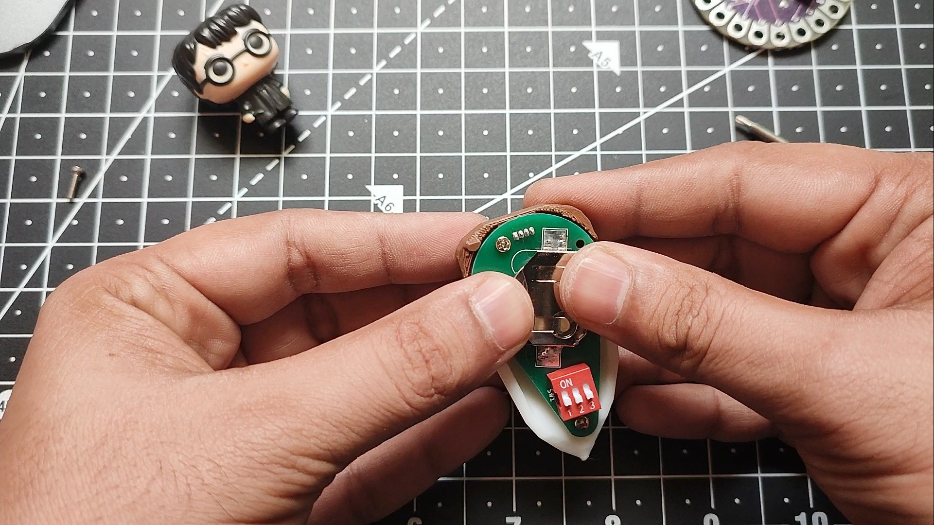
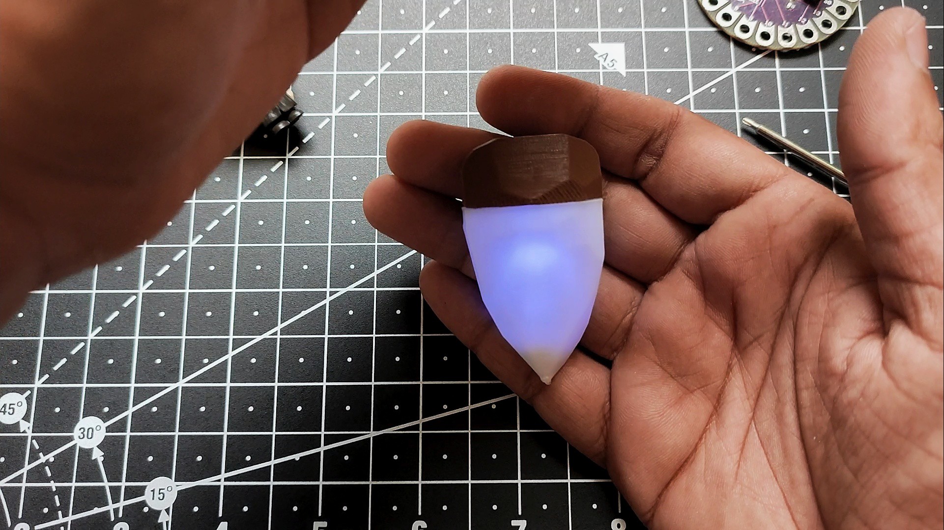
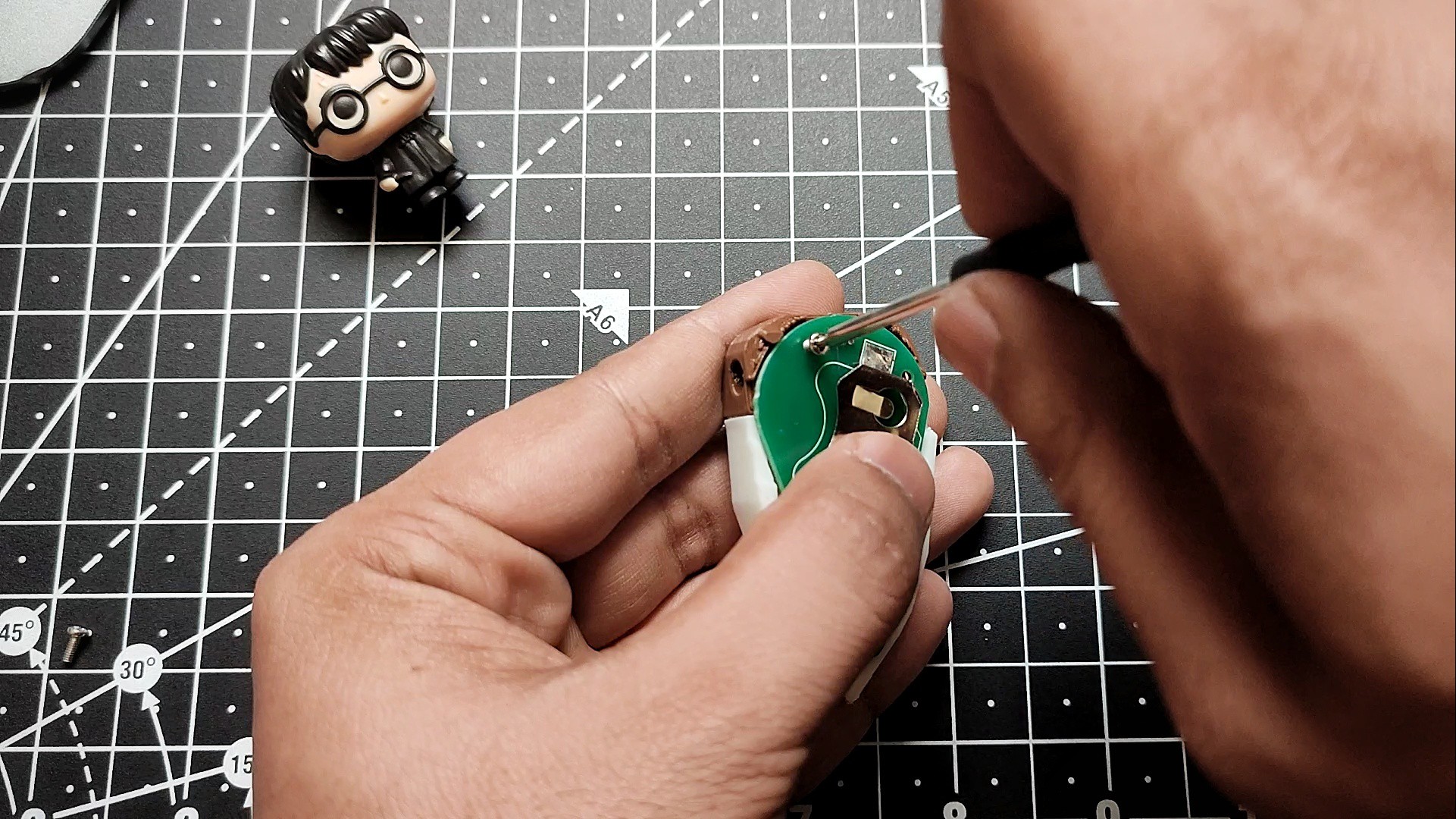
Now it's time for the final assembly of the Aurora Pendant.
Carefully place the assembled PCB inside the 3D-printed enclosure, making sure the RGB LED is properly aligned and the PCB sits flat on the mounting posts. Insert the M2 screws through the PCB mounting holes and tighten them into the heat-set inserts. Tighten the screws just enough to hold the PCB securely in place—avoid overtightening, as it may damage the enclosure or the PCB.
Next, insert the CR2032 coin cell battery into the battery holder, ensuring the positive (+) side is facing the correct direction, as marked on the holder.
Once the battery is installed, test the pendant by toggling the three DIP switches.
Using the Device
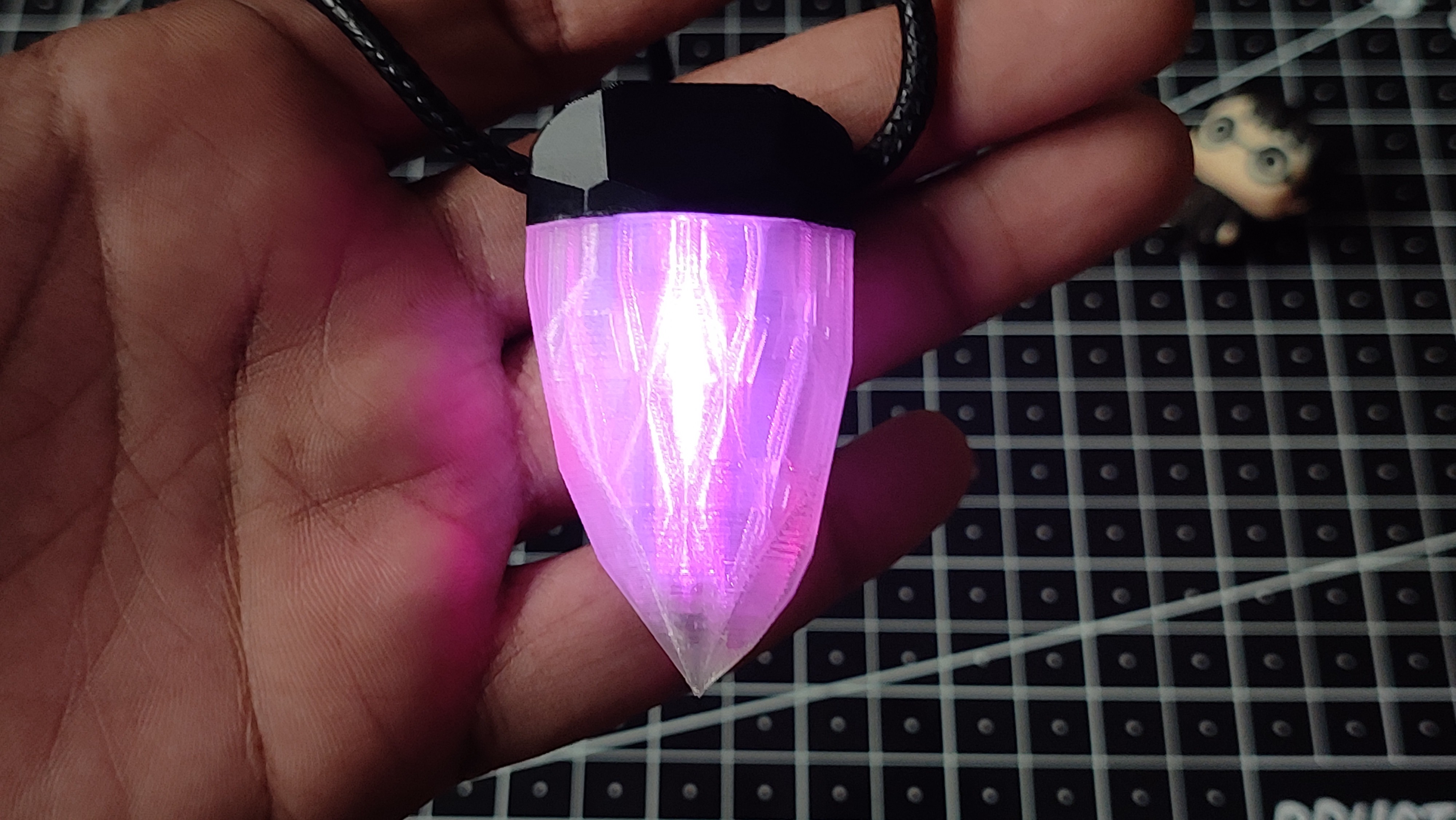
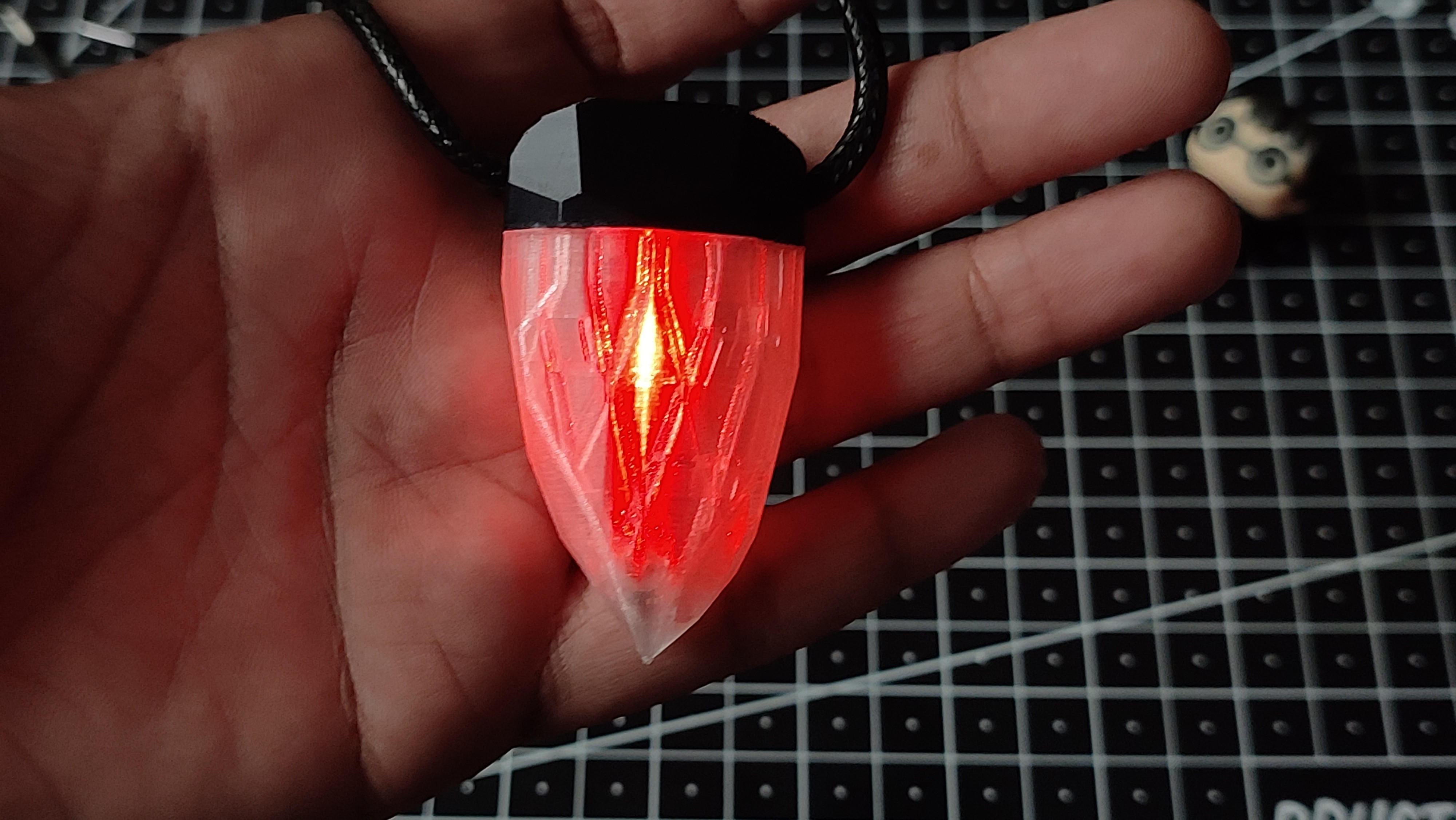
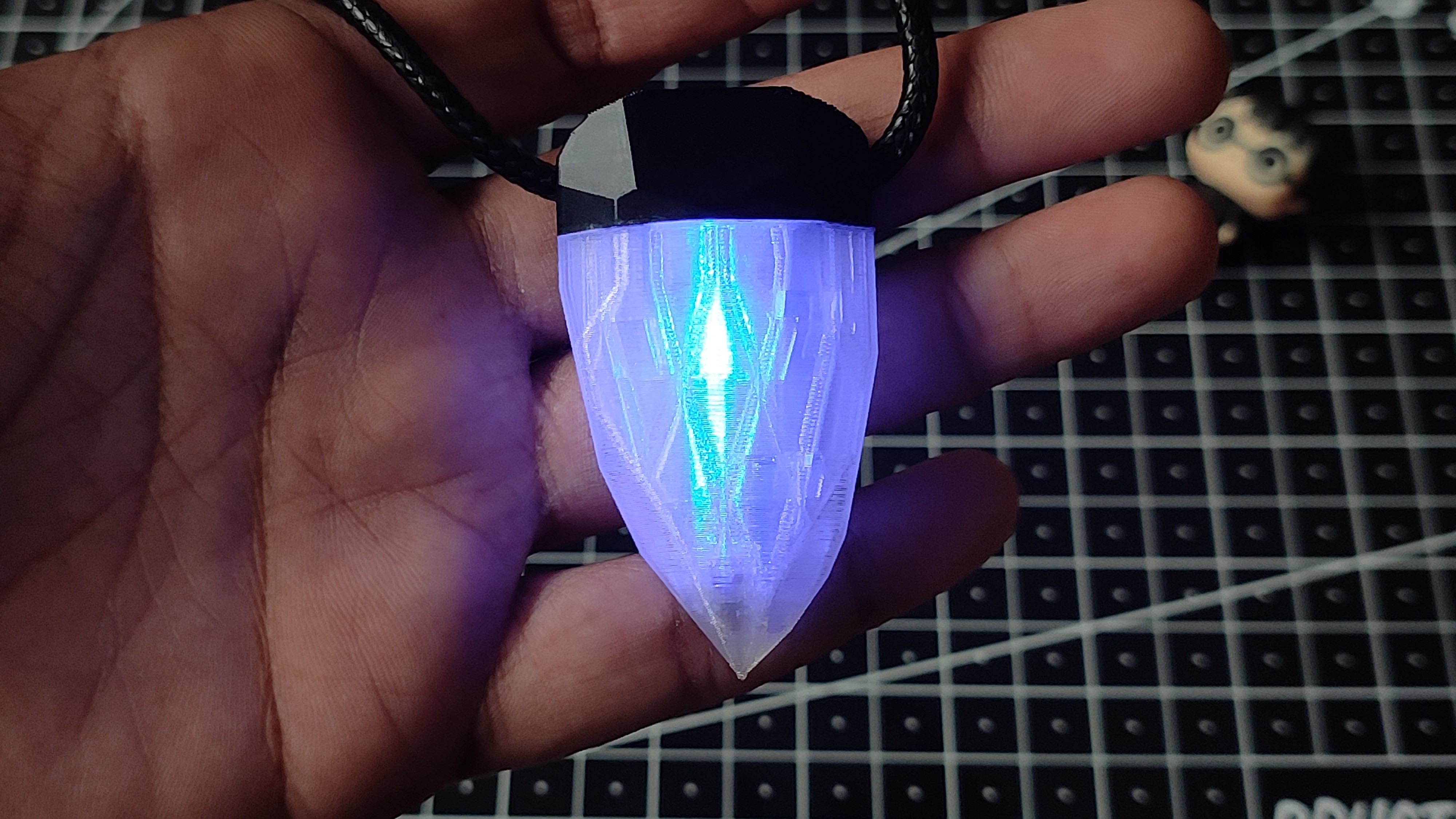
How to Use the Aurora Pendant
Using the Aurora Pendant is incredibly simple. On the back of the pendant, you'll find three DIP switches, with each switch controlling one color of the RGB LED:
- Switch 1 controls the Red LED.
- Switch 2 controls the Blue LED.
- Switch 3 controls the Green LED.
By turning the switches ON or OFF, you can mix the three primary colors to create 7 different color combinations (excluding the all-off state).
- Switch 1 ON → Red
- Switch 2 ON → Blue
- Switch 3 ON → Green
- Switch 1 + Switch 2 ON → Magenta (Red + Blue)
- Switch 1 + Switch 3 ON → Yellow (Red + Green)
- Switch 2 + Switch 3 ON → Cyan (Blue + Green)
- Switch 1 + Switch 2 + Switch 3 ON → White (Red + Blue + Green)
Simply flip the switches to create your favorite color combination and match the pendant with your outfit, mood, or occasion. There is no programming, mobile app, or charging required—just insert the battery, toggle the switches, and enjoy your custom-colored pendant!
Which Looks Good?
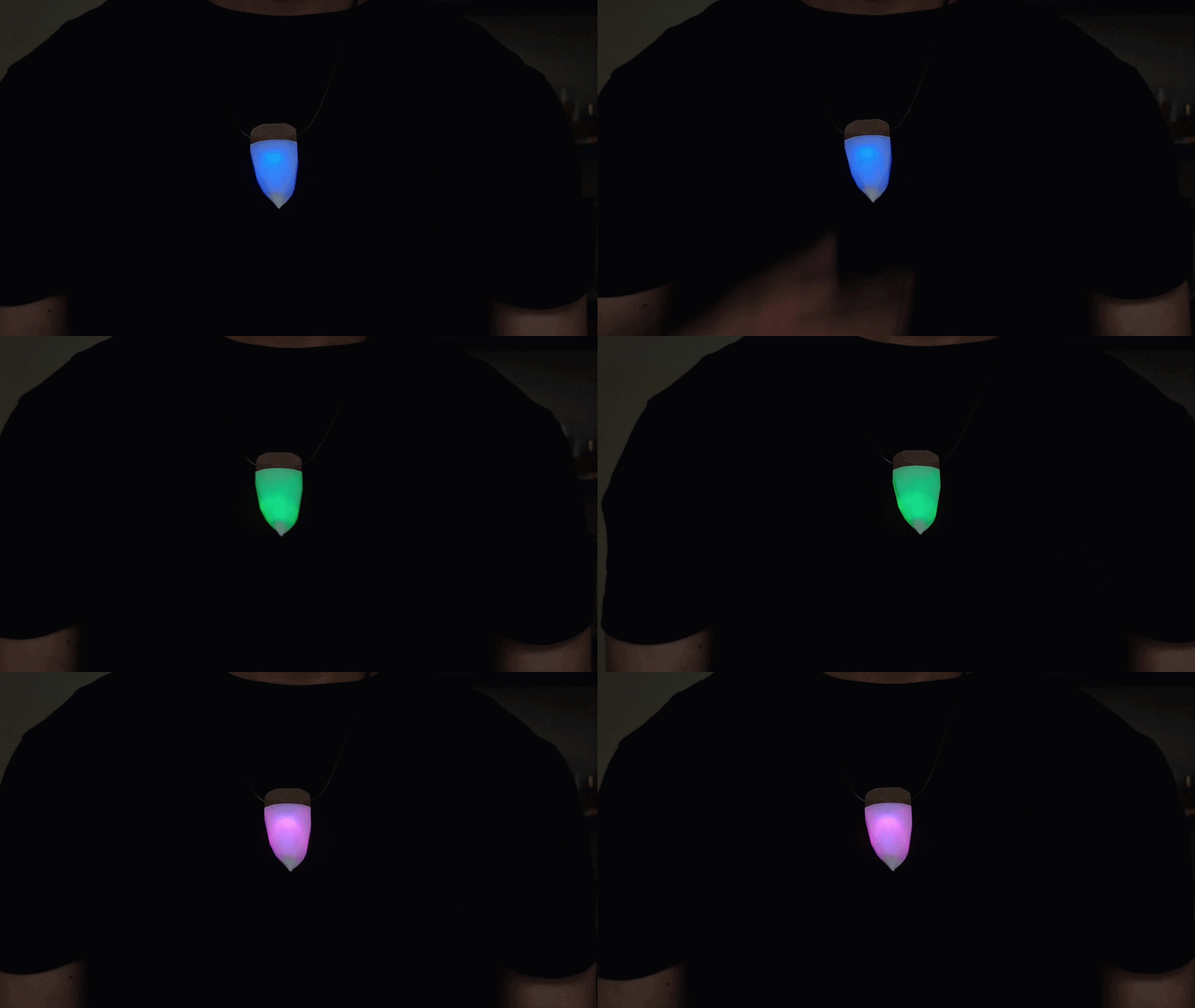
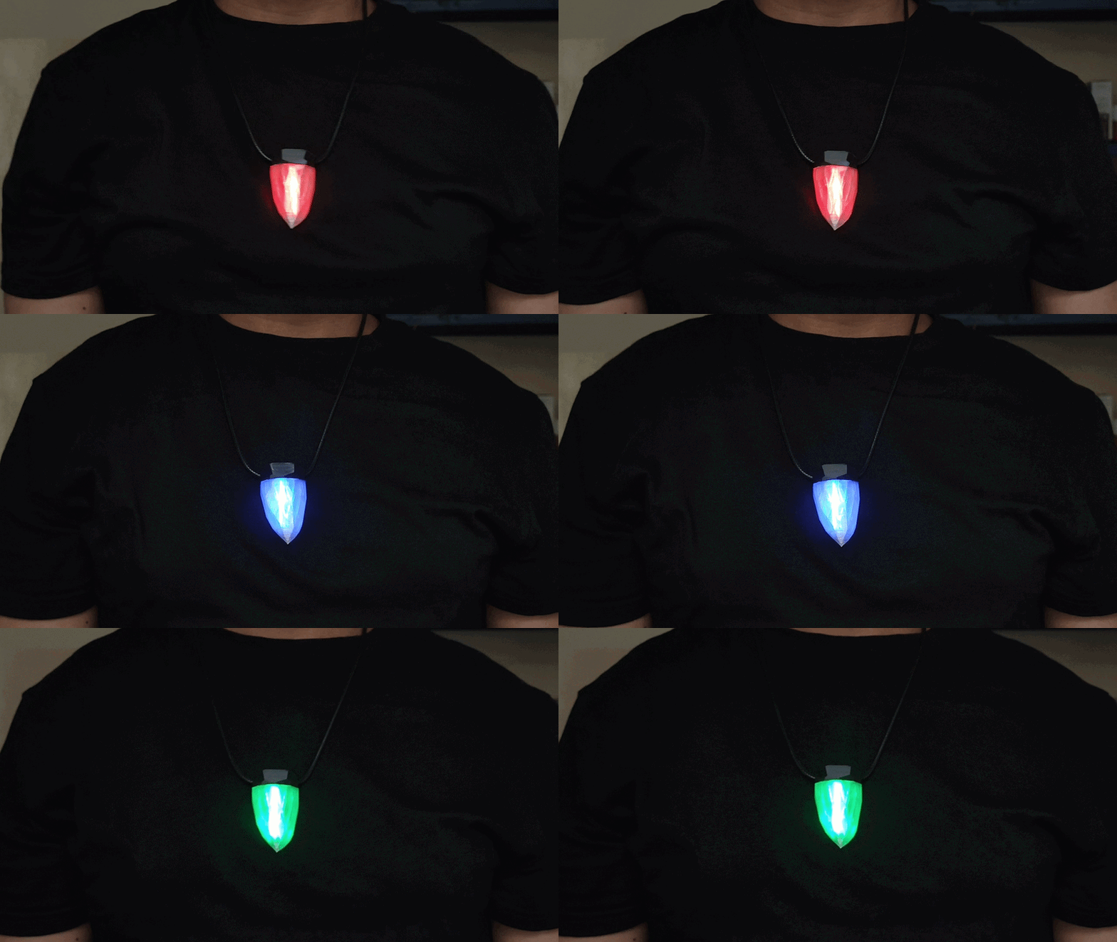
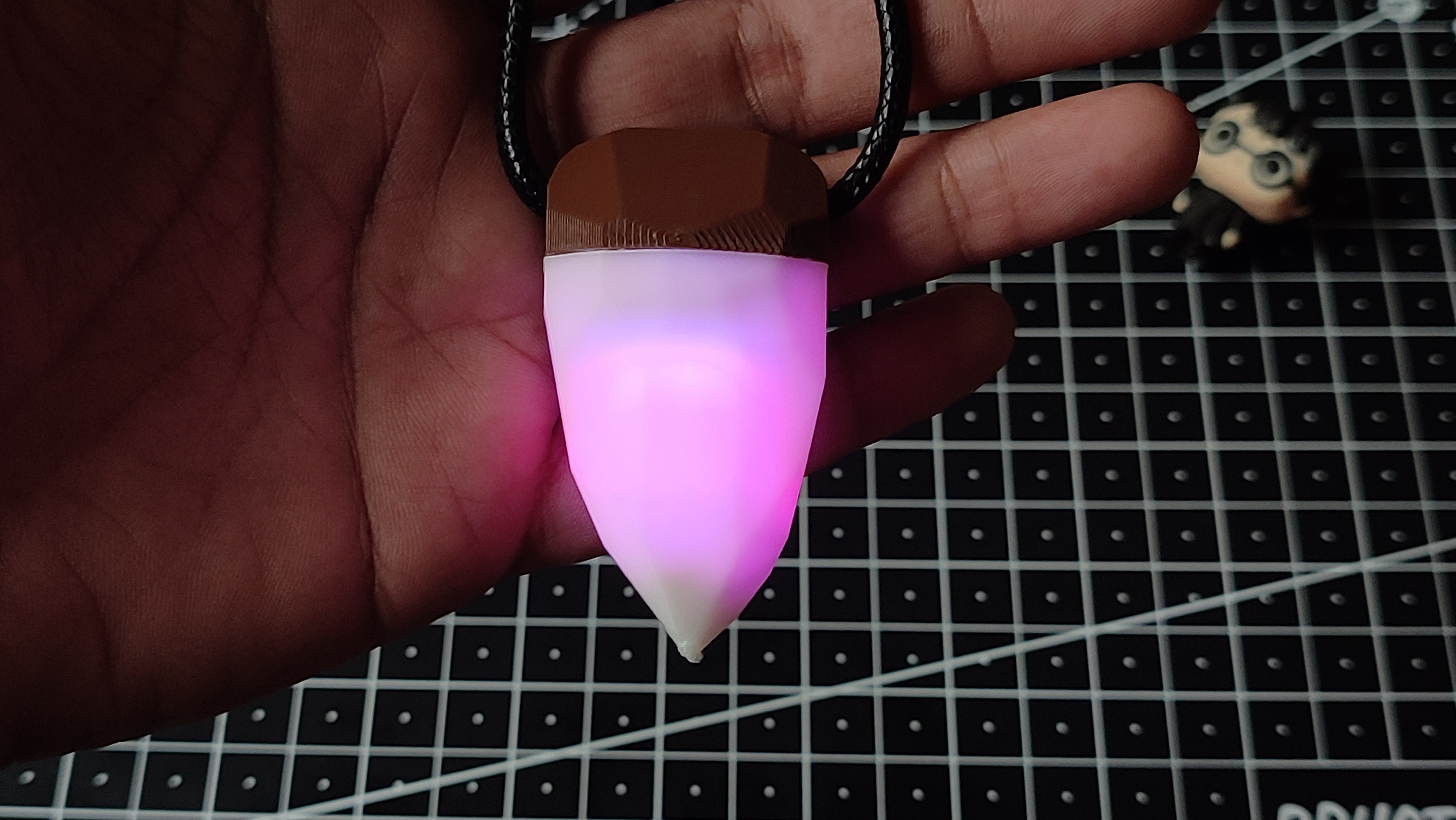
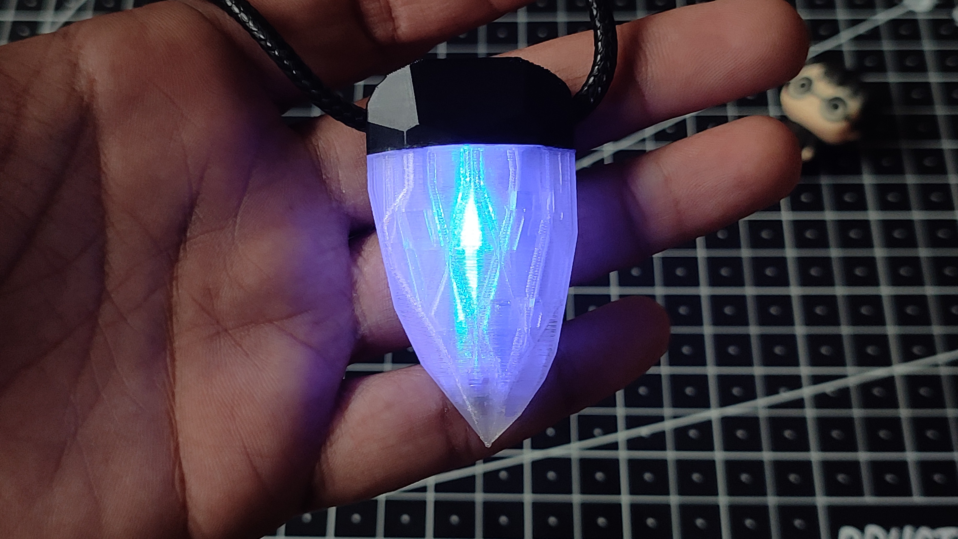
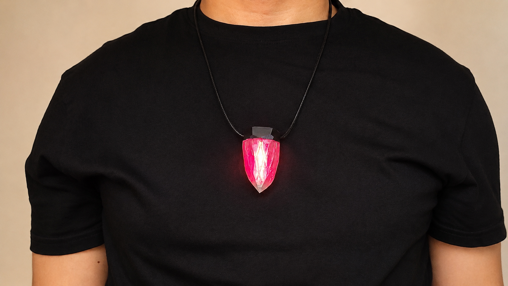
As I mentioned earlier, I designed and printed two versions of the Aurora Pendant so I could compare their appearance and how they diffused the RGB light. You can see both versions in the image—one is printed in solid white PLA, and the other is printed in semi-transparent PLA.
The white version has a clean, elegant look and completely hides the electronics inside, making it resemble a traditional piece of jewelry. On the other hand, the semi-transparent version allows the light to spread throughout the enclosure, producing a brighter, softer, and more vibrant glow. The colors are much more noticeable and create a beautiful crystal-like lighting effect.
Personally, I prefer the semi-transparent version. The light diffusion makes the colors look richer and more eye-catching, especially in low-light conditions. It gives the pendant a unique appearance that really highlights the RGB LED and makes it feel more like a glowing gemstone.
Which version do you like better—the clean white design or the glowing semi-transparent one? Let me know in the comments!
Improvements & Future Ideas
Although the Aurora Pendant works great, there are many ways it could be improved in future versions:
- Replace the CR2032 with a rechargeable battery and USB Type-C charging.
- Add Bluetooth support for smartphone app control.
- Include automatic brightness adjustment using an ambient light sensor.
- Add multiple lighting effects such as breathing, fading, blinking, and rainbow modes.
Buy This 🛒:Link
By the way, Subscribe to my YouTube channelfor more projects like this. I also update my upcoming projects on Instagram.
buy me a coffee! ☕: Donate