 Luis Mestre
Current state of the project is that it is working and rather well. I actually had a look on hackaday and there seem to be other quartz tuning fork AFMs going but no one seems to have gotten nice images. I am fortunate enough to be in the right scientific environment for my work where I can ask people questions when I get stuck and therefore I wanted to put this project on here to perhaps show the other projects is doable and for them to take some ideas out of this was well. I am not sure how much time I will have to document this very throughly especially because I am still improving the setup and want to do this once it's in its final state but I hope it's useful to someone. I want to make a little kit people can buy and just assemble for university labs and hobbyists but I will also work on 3D printed stages anyone can build at home with some time which should be dirt cheap and these I will try to put on here in more detail. The PCB etc I will document at the end once I am happy with it's final state as this was my first iteration and still needs improving.
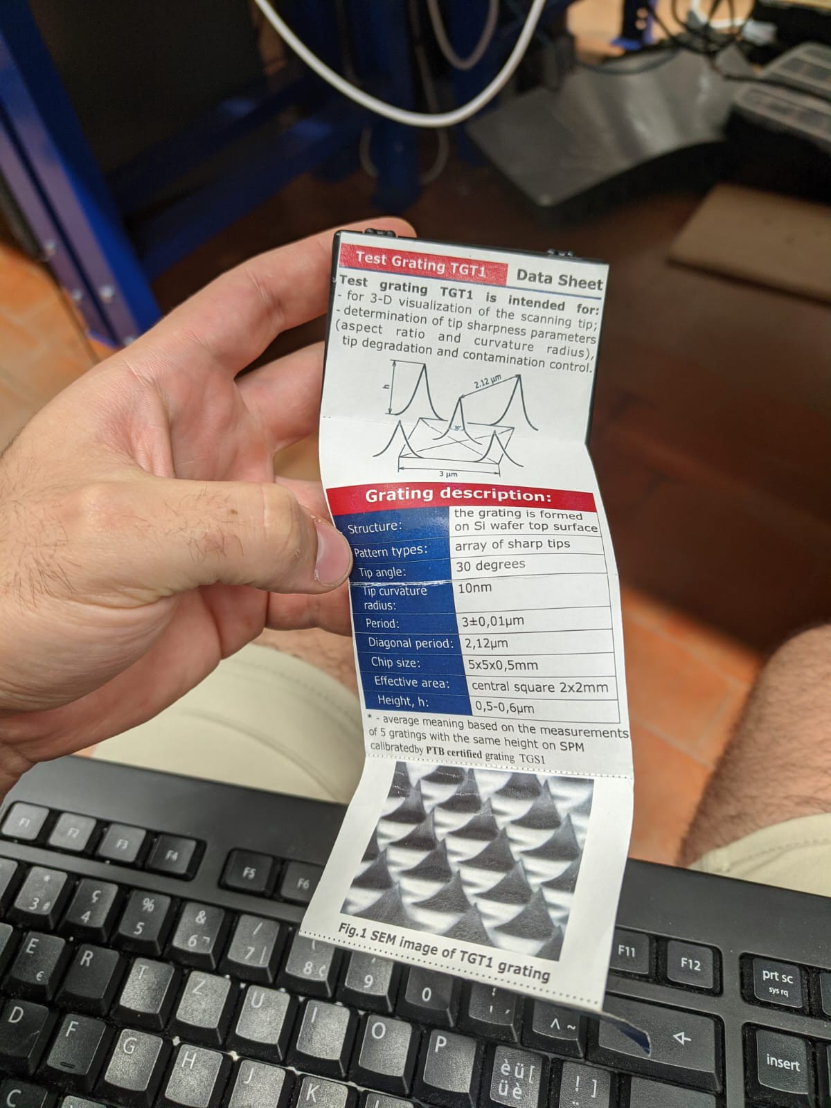
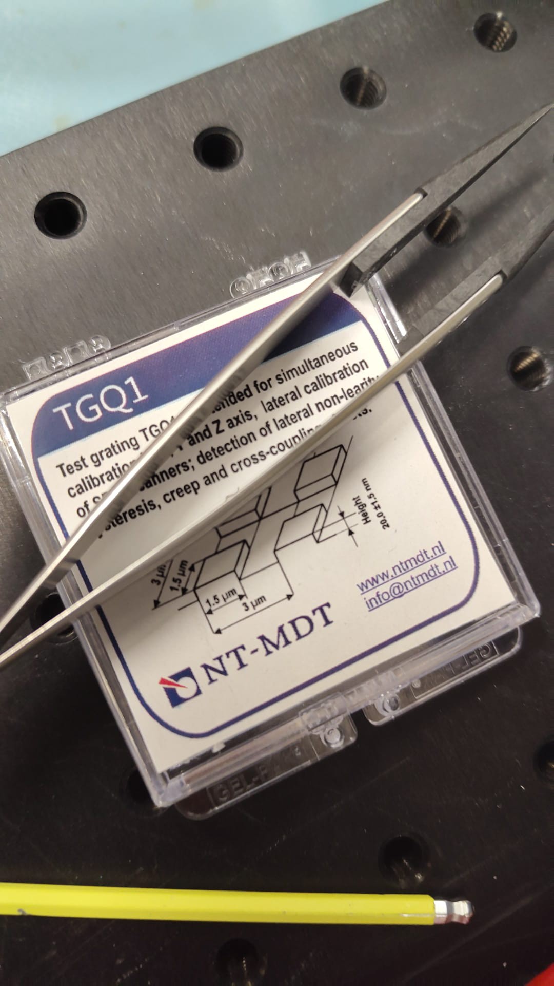
Now for the cool stuff. The images shown are from AFM calibration grids one has steps of 20nm which really require a decent AFM to see. I also tried to image a graphene device with some wires coming out. Bigger calibration grid is quite easy to see. Some examples of images are below
This is the image below
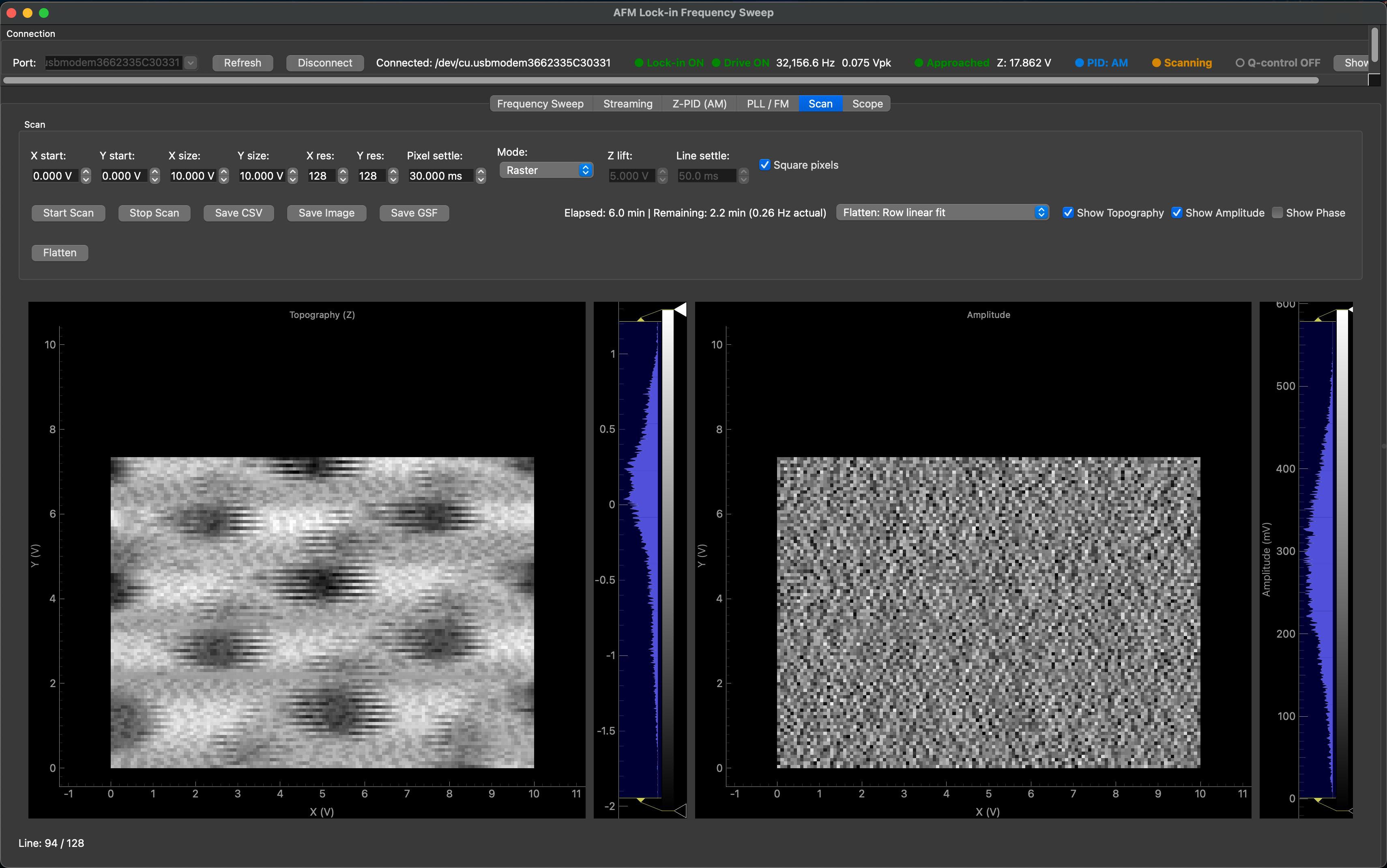
as you can see the forwards and backwards scans during the raster scan have different sizes (the backwards scan is stretched in comparison with the forwards one) I believe this is the piezo hysteresis in the stage. This is fixed by scanning in a single direction. That is, once you reach the end of the forwards scan, you lift the tip move it back reengage the PID and scan again, this unfortunately adds some time to the scan but fixes this issue more or less.
New images I took are now with improved noise from shielding on the tuning fork wires leading to the transimpedance amplifier (TIA) and below you can see a 20nm step from the calibration grid with 20nm high 1.5um wide squares
 Here is an example of the 20nm step with improved noise. The previous steps looked like this:
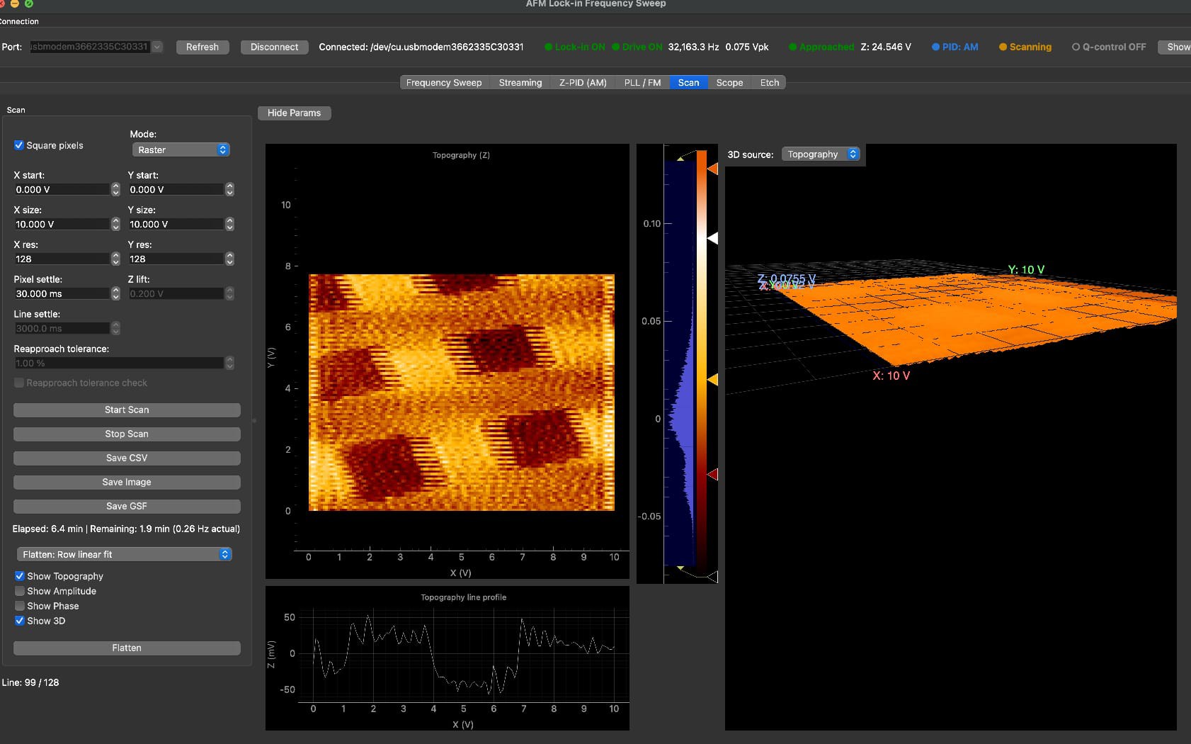 With the improved shielding on the tuning fork wires to the TIA the same 20nm step is much cleaner. I believe now I am limited by environmental vibrations due to my damping being a bike inner tube, to see atomic layers, I likely need and enclosure and the setup suspended by springs with eddy current damping from magnets similar to Dan Berard's STM. but I would say this is pretty good already for most applications like looking at cells or DNA.
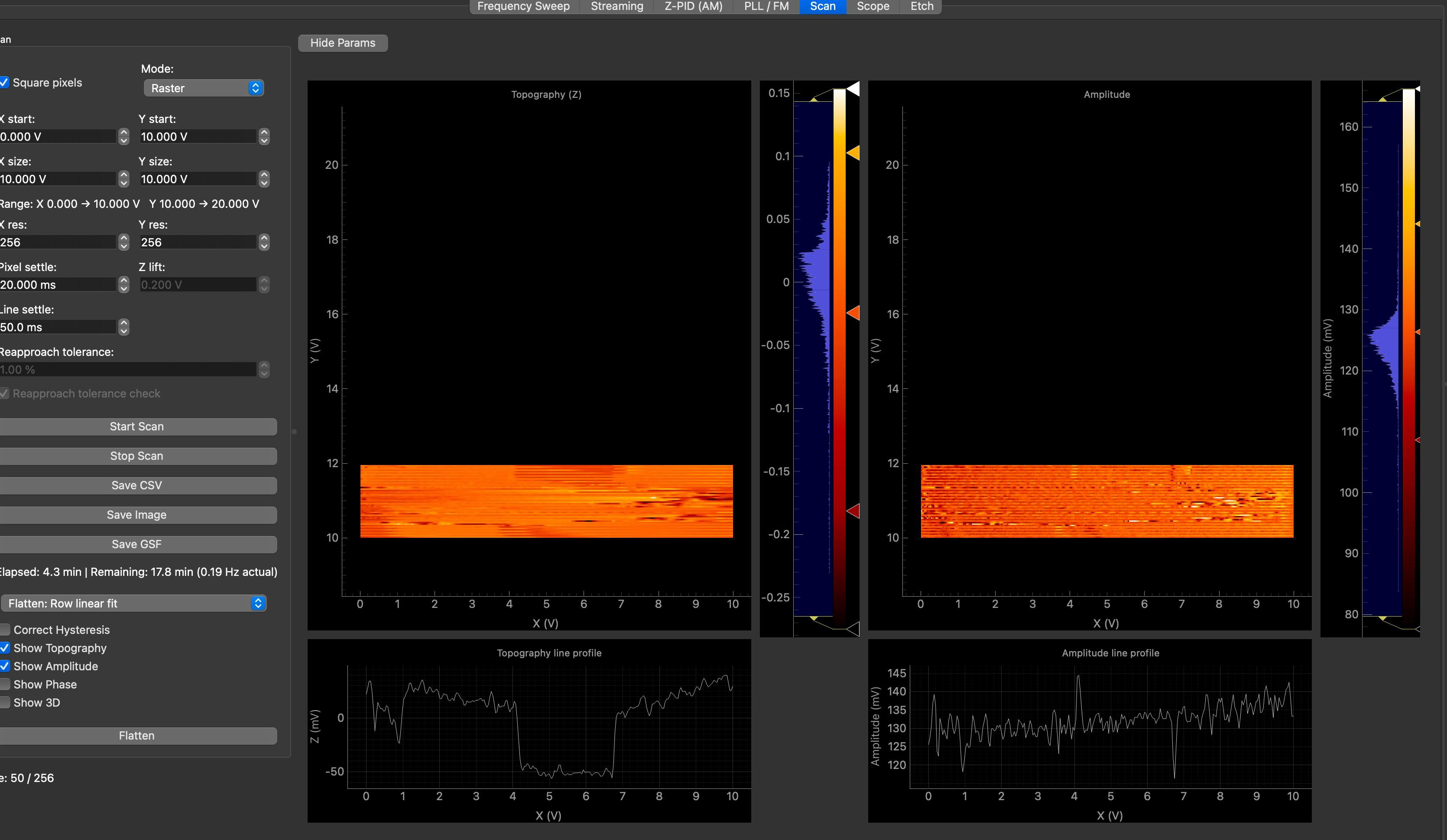 I also imaged the connections wires to a graphene device kindly given to me by a friend where you can see 10s of nm high wires, It's a little hard to see in the topography image without better processing in gwyddion but you can see the e-beam evaporated gold wires coming out from the graphene flake in the amplitude scan quite well.
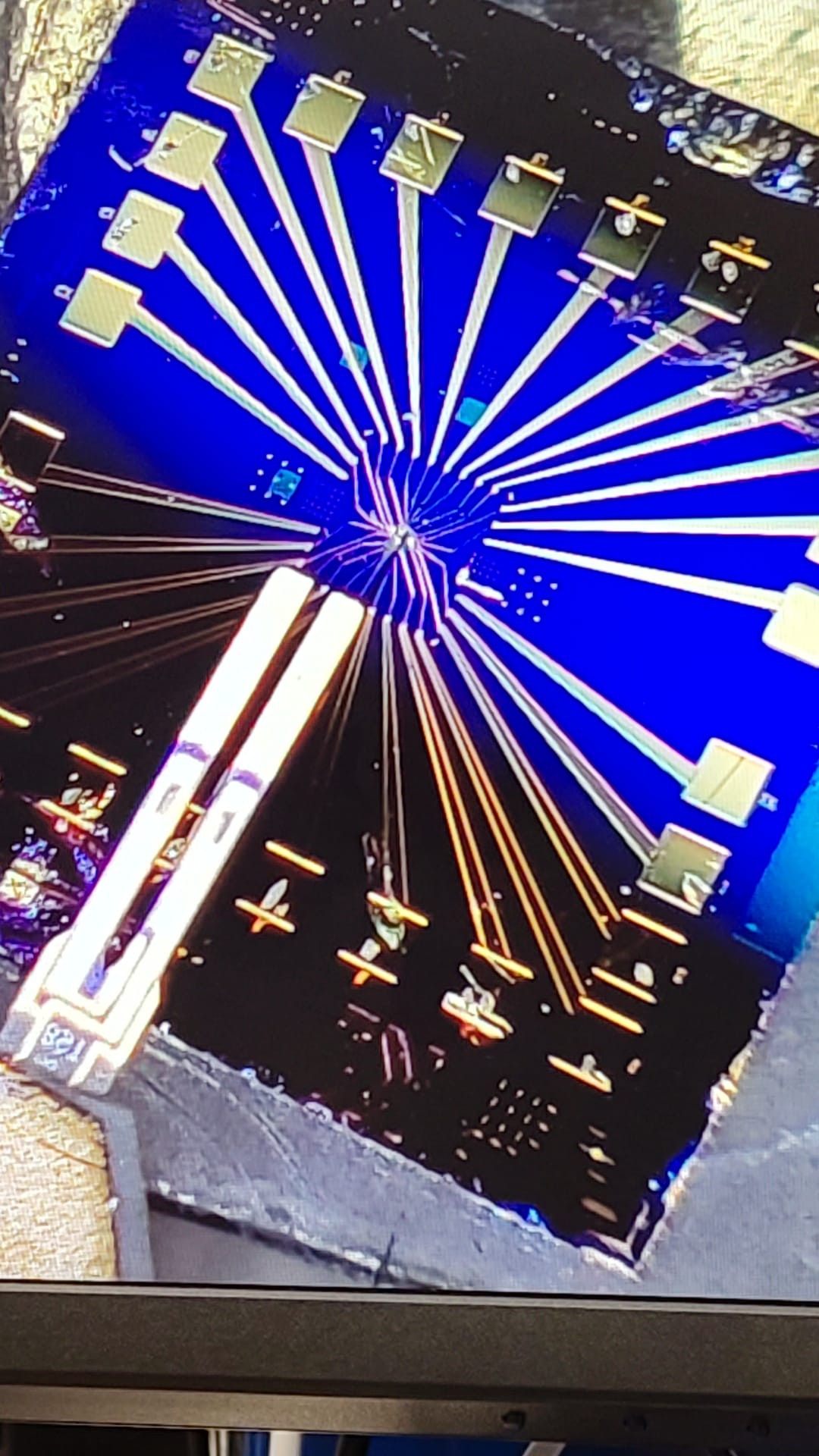
 below is the setup the device is in the middle of the wires
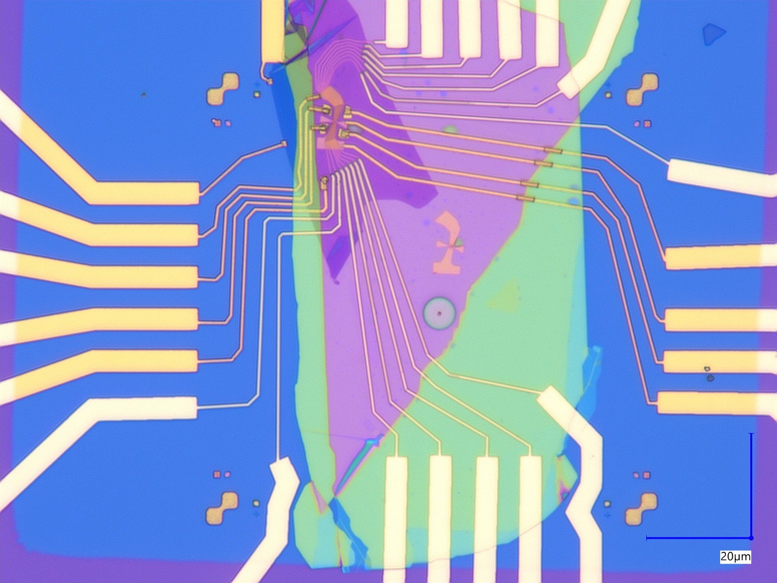
Here is the optical microscope image
I believe this image is on one of the edges of the flake, as I didn't have a great microscope to check where I was and the tip is moved with a hand micrometer stage. With only 15x15um scanning range and the images taking a while it's hard to hit the actual 10ish um device (I didn't have too much time that evening). However, it is still possible to see the 10nm high wires and the graphene should be quite thin as well.
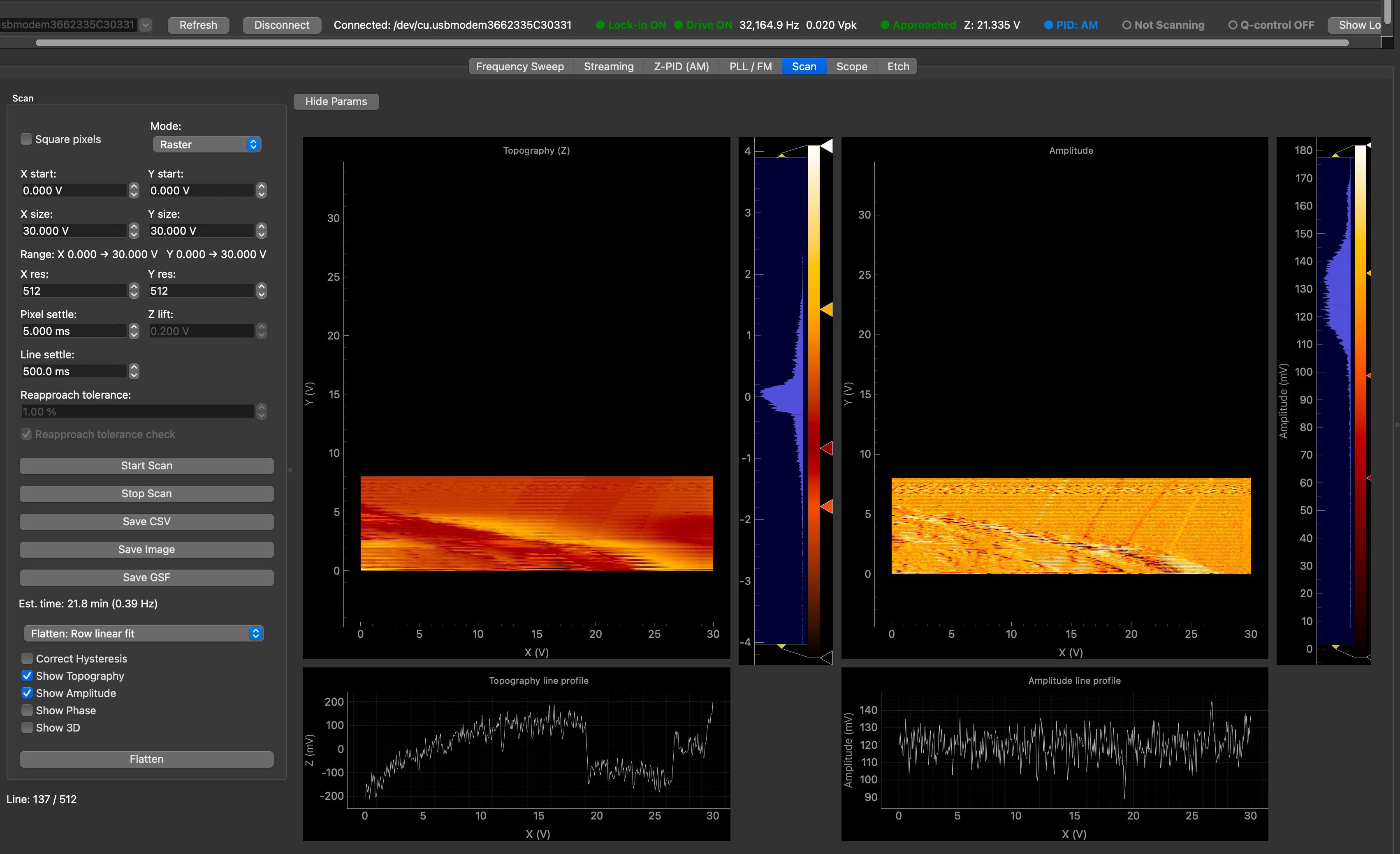 These are all half images because I was trying quite a few things out and I am limited by the bandwidth of my loaded Z piezo buzzer. This means I have to scan quite slowly and the images with high resolution can take quite a bit of time compared to a standard cantilever AFM that will take like 3 min. I actually compared my images to the system we have in the building costing upwards of 200k and mine are really not that bad especially if you don't mind waiting.
 Conclusion:
-The system is currently working reasonably well
-The bandwidth on the z axis needs improving to run the PID faster in order to decrease scanning time
-The hysteresis of the stage is a working progress and will likely be solved with some initial hysteresis calibration before the scan using some rough displacement sensors like strain gauges on the stage to get the hysteresis curve and fit and then run the stage open loop (this should hopefully get it down to like 1% or so)
-Need a motorised rough positioning micrometer stage or stick slip piezo setup similar to Edwin's design https://hackaday.io/project/185518-hacking-any-linear-slidebearing-into-piezo-motor.
Basically the project is still a working progress but I think it's getting there and it's in a good state as it stands even just to play around as a hobbyist looking at cells butterfly wings etc, if anyone has any ideas for easy samples to prepare it would be great if you could drop a comment.
Discussions
Become a Hackaday.io Member
Create an account to leave a comment. Already have an account? Log In.