What is in this test (Introduction)
In this log, I will share my experience with testing of power handling capability of a really cheap USB cable using MightyWatt R3. How cheap? I don't know because I found this cable in my box of USB cables. I probably got this bundled with some device. What you will find inside this test? A (not so) shocking revelation that chinese manufacturers are able to make a cable with virtually no copper at all.
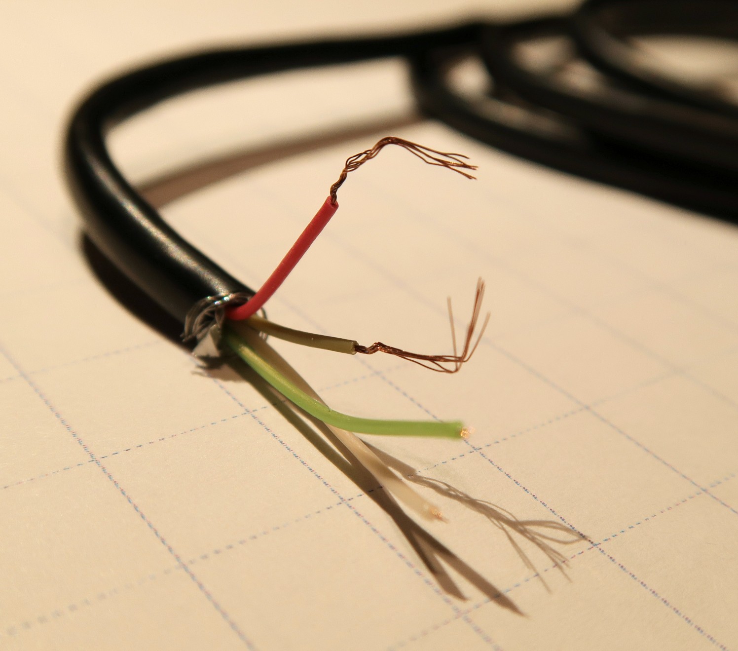
I wasn't really going to test the cable in the first place. I was actually going to test a cheap powerbank I got as a corporate gift. You know, one of those small powerbanks that have a single 18650 cell inside and a boost converter ending in a USB port. And for testing, I needed a cable I could connect to MightyWatt R3. So I cut the cable, saving only the USB-A connector end with a few centimetres of cable. Inside, I found four tiny conductors that had barely any metal in them.
How I tested the cable (Experimental part)
The USB-B connector was cut from the remaining part of the cable, which was subsequently used for the experiment. The length of the cable for experiment was measured using a tape measure. Both ends of the crappy cable under test (CCUT) were stripped and the foil and braided shielding was removed (Figure 1). Using the removed part with the USB-A connector, the power conductors were identified to be red (VBUS) and grey (GND). These conductors were stripped to bare copper and twisted together at one end, forming a single conductor.

A power bank was used as the power supply. A MightyWatt R3 electronic load (24A/3A, 30V/5.5V ranges) was used as the measurement device.
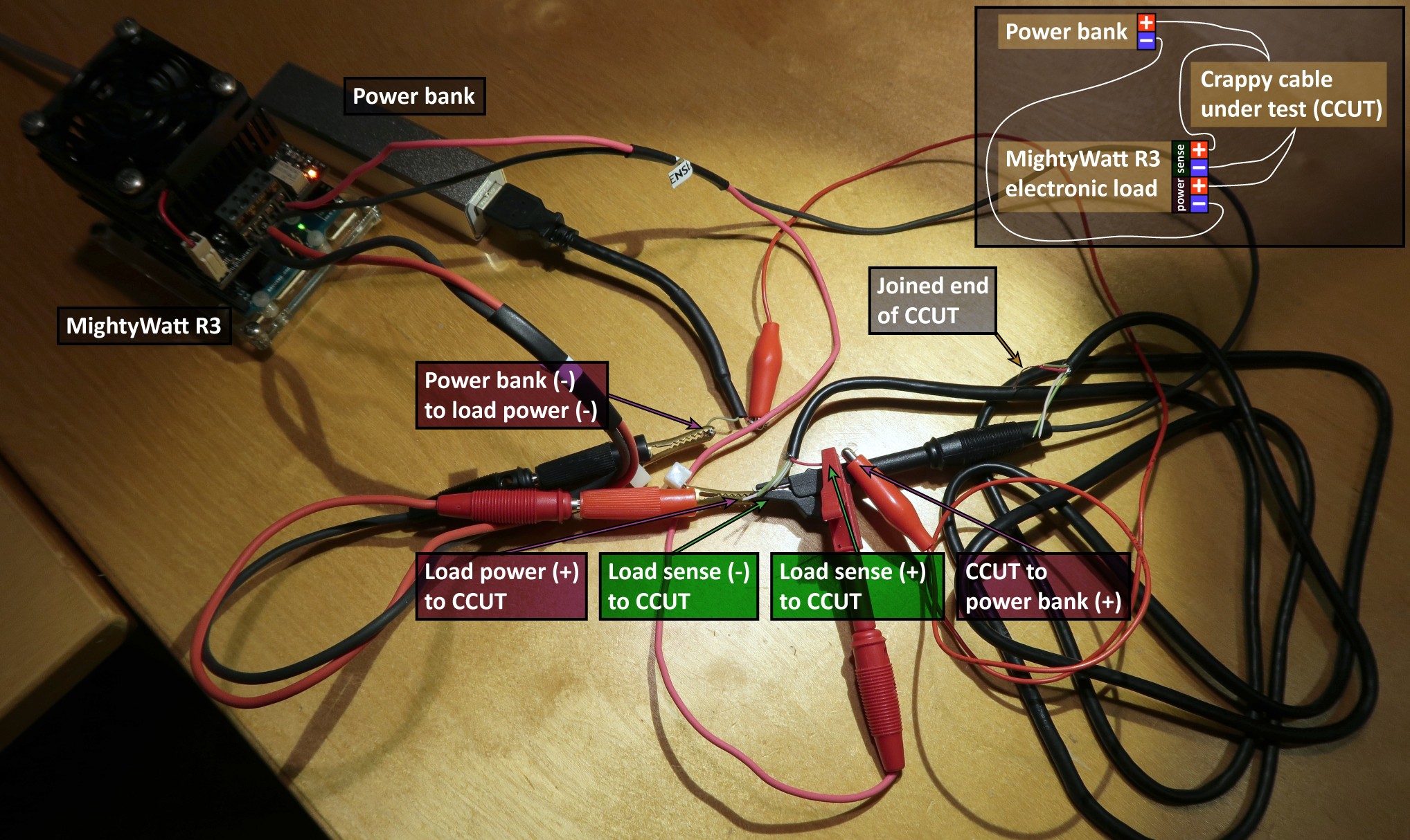
The positive terminal of the power bank was connected to one end of CCUT, the negative terminal was connected to negative (PWR-) terminal of the load. The other end of CCUT was connected to positive (PWR+) terminal of the load. The voltage-measuring (sense) terminals of the load were connected at the ends of CCUT to measure the voltage drop across it (Figure 2).

A 30-second linear sweep from 0 to 0.5 A was applied by the load followed by 60-second constant current at 0.5 A. Voltage drop across CCUT was measured as well as the applied current. The resistance was calculated as a ratio of voltage drop and applied current at the beginning of the 60-second constant current phase. The ambient temperature was 22 °C. Approximate cable gauge was estimated from the experimental data using a table on Wikipedia.
So how bad was it? (Results and discussion)
Pretty bad…
The total resistance was 3.7 Ω and slowly increasing as the cable was heating up. The length of the cable was 1.55 m so back and forth 3.10 m. That means the specific resistance was a solid 1.19 Ω/m, which is horrible. The wire gauge was approximately 36 AWG and its cross-section around 0.0127 mm2, which can be safely rounded to zero :-) If you really put 0.5 A through this cable, you would get 1.85 V drop, which would probably cause any device supplied from that cable not working.
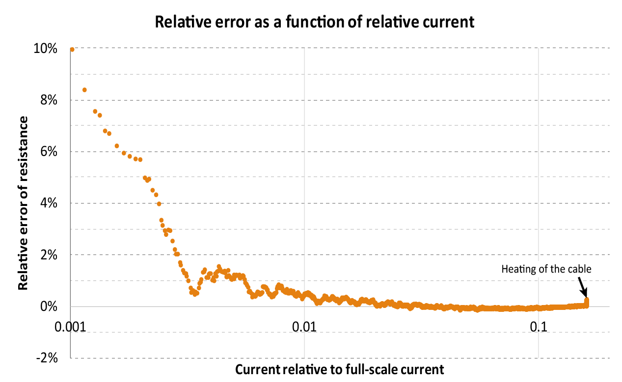
On the bright side, MightyWatt R3 turned out to be great at such an experiment. The accuracy within 1 % was available when the current was a meager 1/180 of the used range (Figure 3).

The bottom line (Conclusions)
Crappy cables are crappy. And at the USB 2.0 maximum current may be totally unusable.
May this be a cautionary tale and also an inspiration how to use an electronic load to measure stuff!
Discussions
Become a Hackaday.io Member
Create an account to leave a comment. Already have an account? Log In.