 Dzmitry Dydyshka
Prerequisite
Getting a device connected and the PSU-EXT Dashboard open follows the Installation section of the psu-ext-software README.
Overview
Our dashboard, backend, and firmware all speak SCPI, the standard ASCII command language for test-and-measurement instruments. Two transports and one WebSocket bridge carry that command language between browser and device — nothing here invents a protocol of its own.
That choice matters in practice. One shared command language means every dashboard widget and script talks to PSU-EXT the same way, regardless of how it's connected. Exposing that language over two transports instead of one means a USB-tethered setup on a workbench and a Wi-Fi-only deployment across the room run on identical firmware, with nothing to swap out between them.
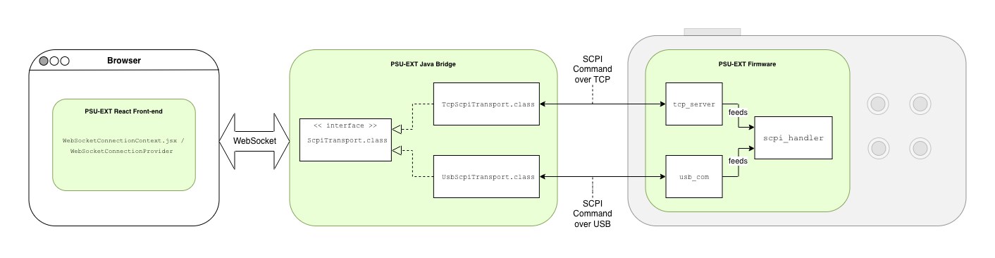
One query, one bridge, two possible transports, one firmware dispatcher.
The stack behind it
Front-end ( psu-ext-software/psu-fe )
- Framework: React 18.3.1 + React Router 6.30.1, built with Vite 6.0.5
- Styling: Tailwind CSS 4.1.0 (via the @tailwindcss/vite plugin)
- Charting: uPlot 1.6.32 — the live telemetry chart widgets
- Icons: lucide-react
- Testing: Vitest 4.1.5 + Testing Library (React, jest-dom), jsdom
Back-end ( psu-ext-software/psu-be )
- Language/runtime: Java 25, Maven multi-module build (parent + BOM pattern)
- Framework: Spring Boot (version pinned via the psu-be-bom/parent POMs; spring-boot-maven-plugin 4.0.6)
- Transport-specific: spring-integration-ip (backs "TcpScpiTransport.class") and jSerialComm (backs "UsbScpiTransport.class")
- WebSocket: spring-boot-starter-websocket — backs "ScpiWebSocketHandler.class"
- Serialization: Jackson (jackson-databind, jackson-datatype-jsr310) - Testing: JUnit 5 + Mockito across all modules
SCPI: the command language, not the wire
SCPI (Standard Commands for Programmable Instruments) is an established, ASCII-text command-set standard for controlling test-and-measurement instruments. It's built on IEEE 488.2-1992, the message-exchange and common-command layer originally defined for GPIB (General Purpose Interface Bus) instruments under IEEE-488.1, and it grew up in the context of GPIB and VXIbus test gear. Its latest formal revision is commonly referenced as "SCPI-99."
The format is hierarchical and colon-separated: a command like "MEAS:VOLT?" addresses a "MEASURE" subsystem's "VOLTAGE" node. Commands defined by IEEE 488.2 itself — the ones every SCPI instrument shares regardless of what it measures — are prefixed with an asterisk, such as "*IDN?", "*RST", and "*CLS'. A trailing question mark on the header is what distinguishes a query, which expects a reply, from a plain command, which doesn't.
Crucially, the standard is transport-agnostic by design: it defines the command language, not the physical or electrical link it rides on.
PSU-EXT's own SCPI commands
Our command surface implements exactly one IEEE-488.2 common command:
*IDN?
, which returns
PSU-EXT,ESP32-S3,0001,0.1.0
and is handled before anything else, ahead of the per-family dispatch chain. Beyond that, everything is organized into eight command families:
| System (`SYST`) | "SYST:ERR?" returns "0,"No error"; "SYST:DATETIME" sets a runtime wall-clock mapping that isn't persisted across reboots |
| Measure (`MEAS`) | "MEAS:VOLT? CH1" and "MEAS:CURR? CH1' read output voltage and current; "MEAS:VOLT:DATA? CH1" returns a binary block of stored history records. |
| Calibration (`CAL`) | "CALibration:STARt VOLTage,CH0" opens a calibration transaction; "CALibration:COMMit" validates the staged points and writes them to non-volatile storage. |
| Output (`OUTP`) | "OUTP CH1,1" energizes the output relay (after clearing latched protection and checking the input-voltage condition); "OUTP? CH1" reads the relay state back. |
| Protection (`OVP`/`OCP`) | "OVP CH1,<value>" sets the over-voltage threshold; "RESET:PROTect CH1" clears a latched protection trip |
| Timer (`TIMer`) | "TIMer:ADD CH1,<id>,<seconds>,<0|1>" queues a delayed relay transition; "TIMer:STATus? CH1" reports whether that queue is idle, running, paused, or tripped. |
| Trigger (`TRIG`) | "TRIG:CONF <trigger>,<HIGH|LOW>,<function>" maps a GPIO edge on one of the two physical trigger inputs to an action like turning the output on or starting a timer. |
| WiFi (`WIFI`) | "WIFI:SSID <ssid>" and "WIFI:PASS <password>" store network credentials; "WIFI:STATUS?" reports the live connection state. |
Some of that lines up with standard SCPI convention, some of it doesn't.
`SYST`, `MEAS`, `CAL`, `OUTP`, `OVP`,`OCP`
all use subsystem names and query syntax that read the way a generic bench instrument's SCPI set would; the specific behavior underneath — CH0/CH1 channel semantics, the calibration stage/commit procedure, the pre-enable interlock on "OUTP", the exact threshold defaults on "OVP`/`OCP" — is ours.
WiFi configuration is the clearest example of something we added outright: there's no "WIFI" subsystem anywhere in the SCPI or IEEE-488.2 standard, so "WIFI:SSID", "WIFI:PASS", "WIFI:CLEAR", and "WIFI:STATUS?" have no standard analog to diverge from at all — we needed a way to configure the device's own network connection over the same command channel already used for everything else, so we added one.
Two transports
That whole command set — the standard-shaped families and the ones we added ourselves — reaches PSU-EXT over one of two physical connections: TCP or USB.
Adding a device starts from the dashboard's Config page: the "Device List" widget carries a "Add Device" button that opens a form offering the same TCP/USB choice. The device profile it creates is saved server-side rather than in the browser, so it's still there the next time anyone opens the dashboard, from any browser.
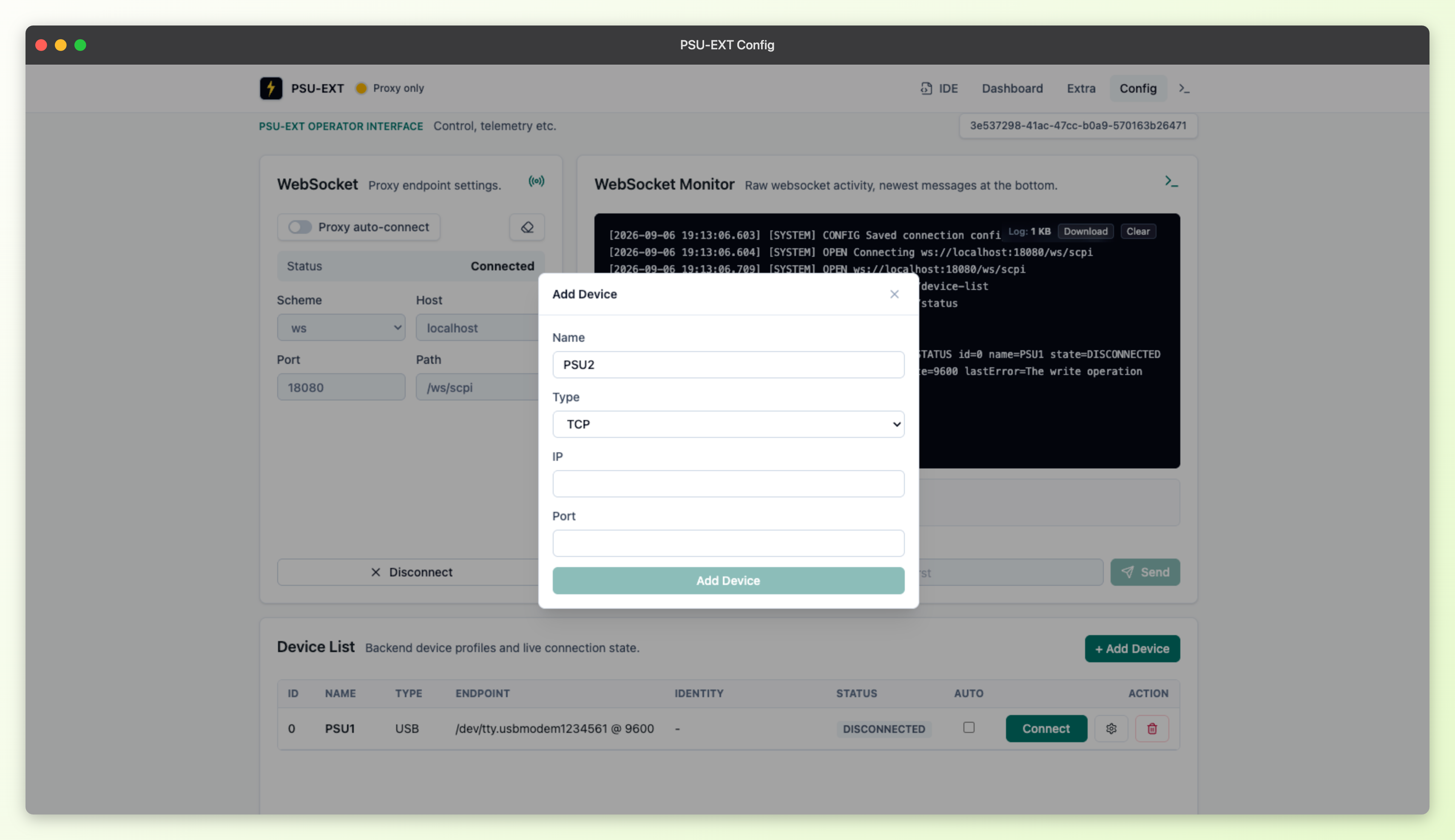
Our TCP transport's default target is "192.168.4.1:5025".
USB connects as a standard USB-CDC virtual COM port, so it shows up like any other serial device once plugged in.
We also have two independent physical status LEDs, one per connection: a red LED on GPIO17 for USB status and a blue LED on GPIO18 for Wi-Fi status. Each lights solid once its connection is up. Wi-Fi additionally shows a slow breathing ramp while it's connecting; USB has no connecting state of its own, just connected, failed, or off. Both use the same fast-triple-blink-then-pause pattern to signal a failure, and both go dark when idle.
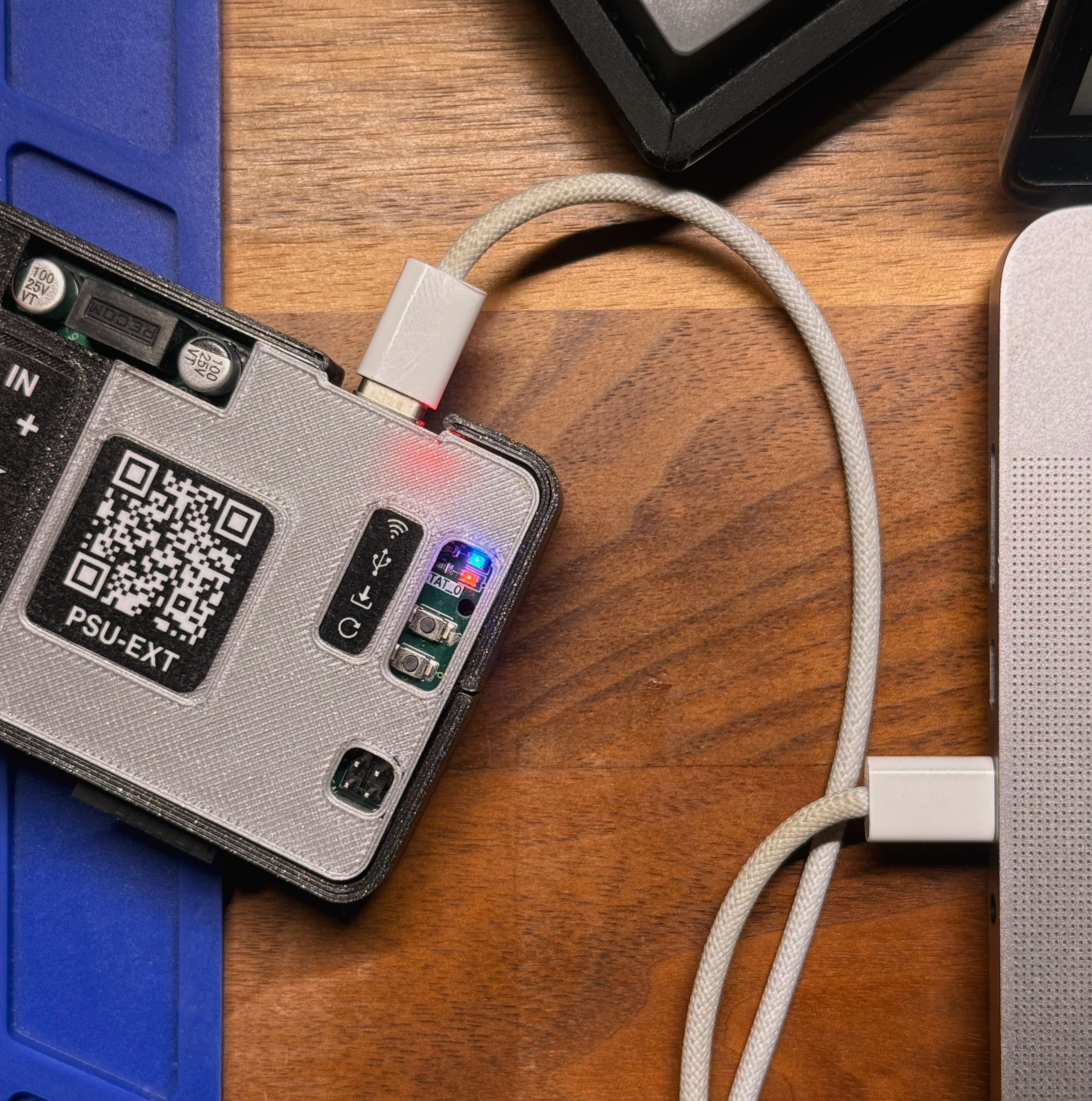
WiFi and USB Status LEDs
The Java bridge and WebSocket layer that normalizes both
The bridge is the piece of our backend written in Java that sits between the browser and whichever transport a device uses. It takes a command in from the browser's WebSocket connection, sends it out over TCP or USB, and relays whatever comes back straight to the browser.
Both transports behave identically from the bridge's point of view — connect, send a command, wait for a reply if it's a query — so the bridge itself doesn't care which one a device is using. The dashboard's live telemetry charts poll frequently - each poll a "CMD <device> <query>" request — and running all of that over one persistent connection avoids the overhead of opening a fresh one for every query. The built-in SCPI console widget rides the same bridge: a command typed there goes out over the identical channel as the charts' polled queries.
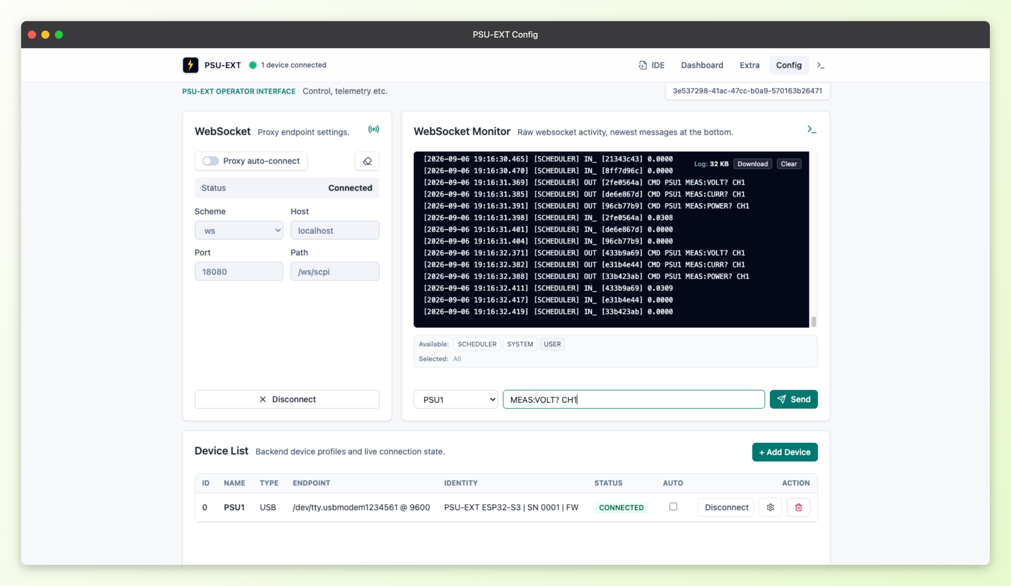
Under the hood, that channel is a single WebSocket endpoint, "/ws/scpi", carrying a simple text envelope. Inbound frames use a "REQ <uuid> <payload>" format:
REQ 3f9c... /connect TCP-Bench-1
REQ 3f9c... MEAS:VOLT? CH1
Slash-prefixed commands (`/device-add`, `/device-list`, `/device-modify`, `/device-delete`, `/connect`, `/disconnect`, `/status`) handle device management; anything else is forwarded as raw SCPI text.
Outbound frames reply with
RES <uuid> <payload>
for plain text and acknowledgements like
OK SENT`, or `BIN <uuid> <base64-scpi-block>
for binary SCPI definite-length blocks such as the reply to "MEAS:VOLT:DATA?".
Firmware's own shared dispatcher underneath both transports
Our firmware mirrors the same split on the device side. Every incoming command, regardless of which link it arrived on, lands at:
scpi_handler_handle_command()
It uppercases the command keyword and chains through handler families in order — system, measure, calibration, output, protection, timer, trigger, and WiFi — before falling back to
ERR,"Unknown command"
Two components feed that one dispatcher.
- "usb_com" is a USB CDC ACM interface on TinyUSB, exposed as a virtual COM port and line-buffered until it sees a CR/LF.
- "tcp_server" is a raw TCP server on port 5025, with a listen backlog of one and a single active client socket.
Neither touches output, measurement, or protection logic on its own; both just hand the received line to the dispatcher.
Where this leaves us
That's the full path, end to end: one SCPI command surface, exposed over TCP or USB, unified by one WebSocket bridge for the browser, and landing on one shared dispatcher in firmware regardless of which link it came in on. Nothing here is aspirational — it's what's running on PSU-EXT today, and it's the foundation every dashboard widget and script in this project builds on.
Source links:
Follow Along on Crowd Supply
If you're interested in PSU-EXT, subscribe to our pre-launch page on Crowd Supply: crowdsupply.com/maxeelabs/psu-ext
Discussions
Become a Hackaday.io Member
Create an account to leave a comment. Already have an account? Log In.