 Kartikeya

First get an old small monitor that you don't mind destroying, it may take a couple of tries until you manage to have a fully working one, after that you can move on to better and larger sizes.
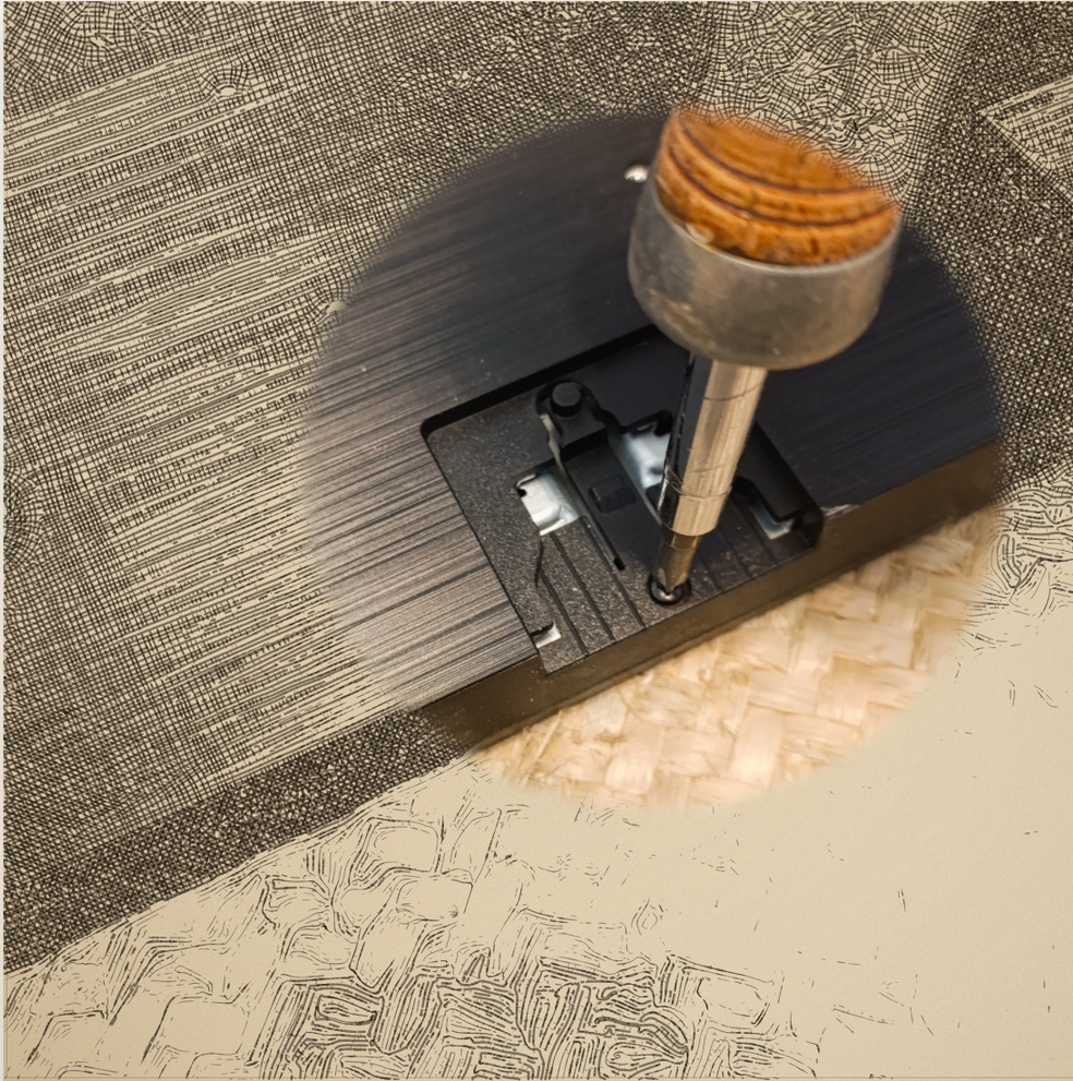 • Find any screws in the back and unscrew them
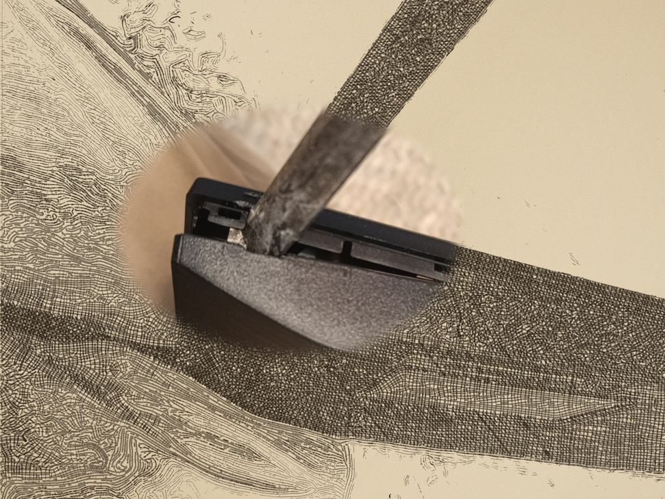
• Find a suitable entry space and remove the bezel carefully in a twisting action, do not to insert the tool edge too far in or you may irreparably damage the inside components, make your way carefully little by little in one direction until bezel starts coming apart.
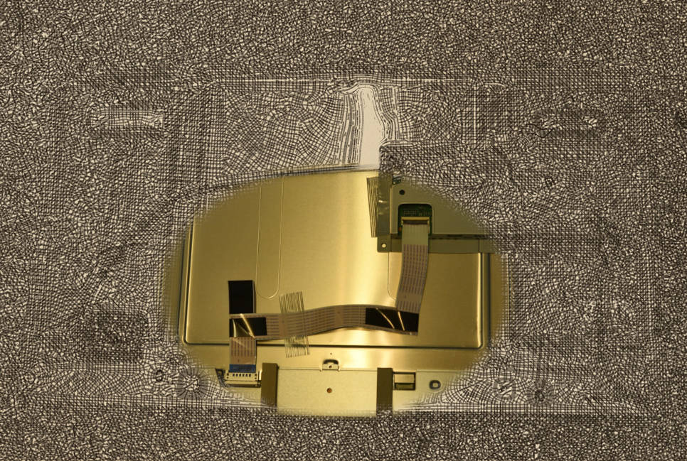
• Remove the back cover until you see the entrails
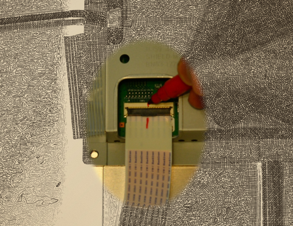
• Mark ribbon connectors and mark them with a line on both ends to register the position which we will later need
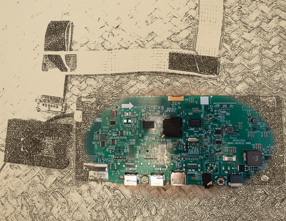
• Very carefully remove one and then the other cable until you are able to get the card out.
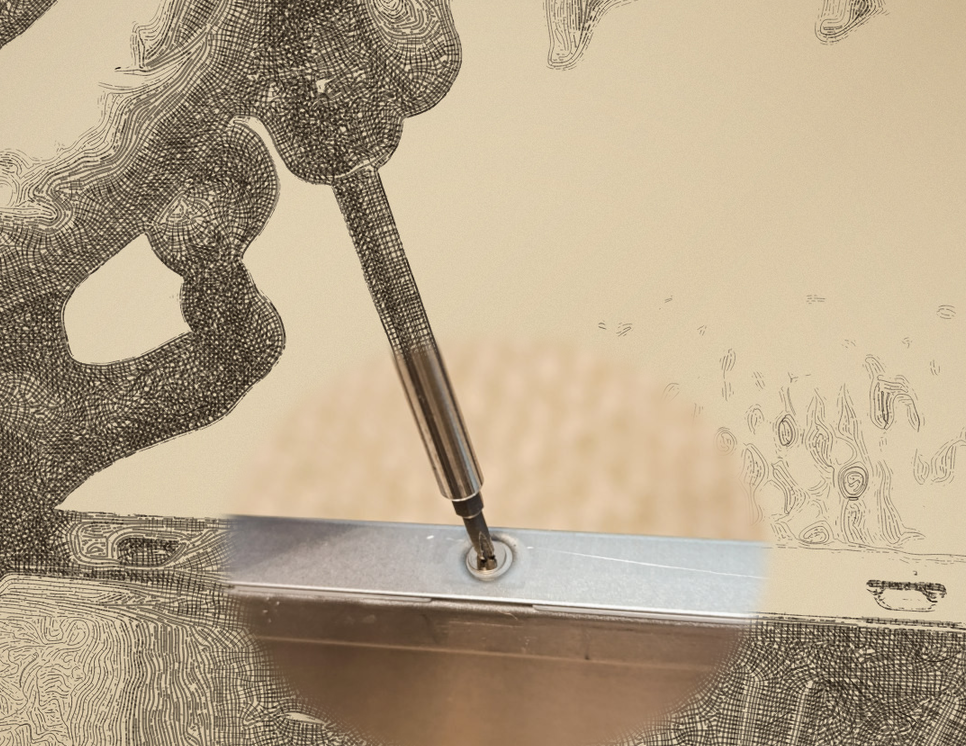 • Very carefully turn the panel to the side and find any side screws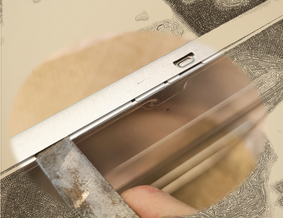
• You may also find these latch locks holding a frame in place.
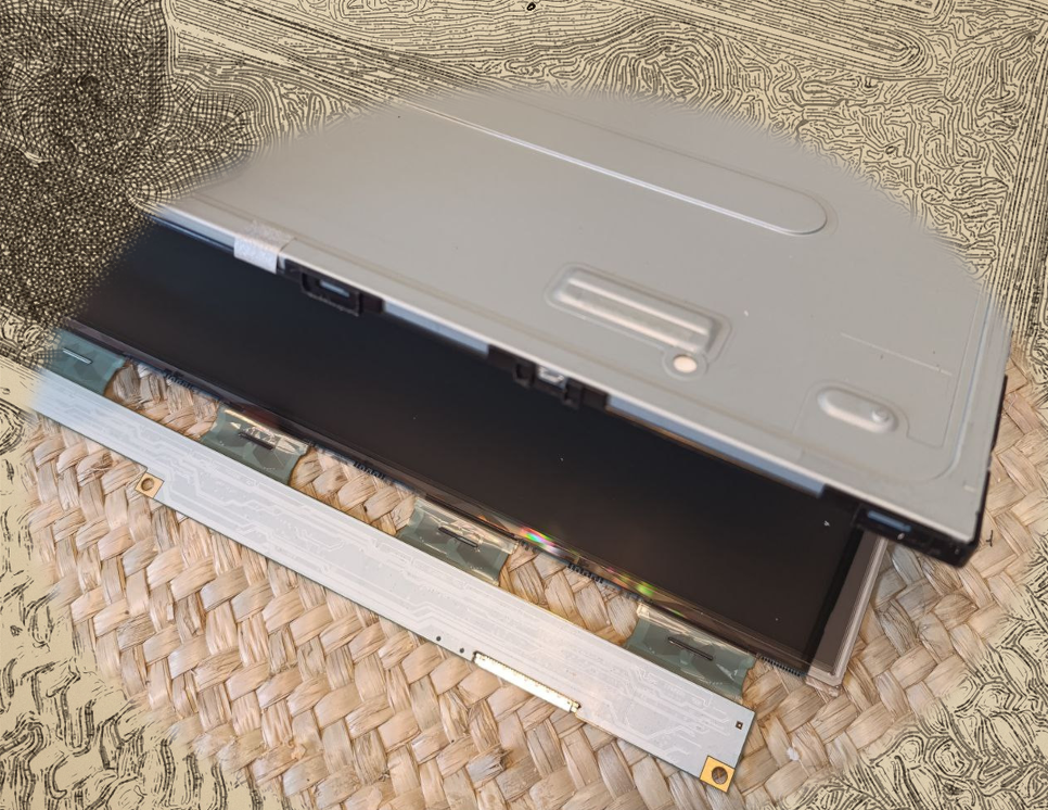
• You should be able to remove the cover and frames effortlessly, if you feel that its does not come out easily, do not force anything and see what is keeping it held
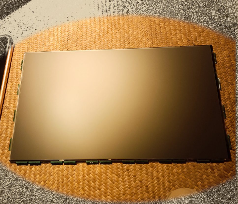
• Place the panel in a clean safe place face down ( viewing side down), with utmost attention to the ribbon cables to not touch or move them too much, handle it as the most delicate flower petals.
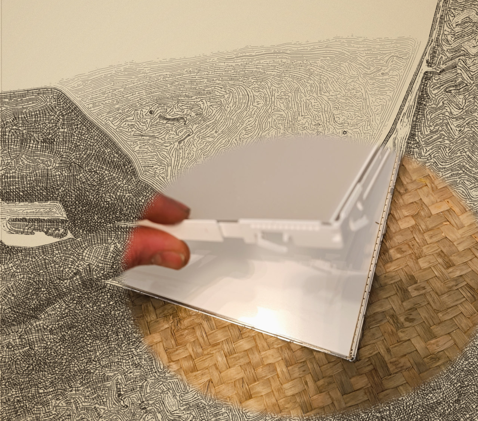
• With the rest of the module carefully snap out everything and pull it apart, saving the soft matte sheet and put them directly into the back of the LCD panel, and also save the hard acrylic sheet, discard the prismatic looking ones.
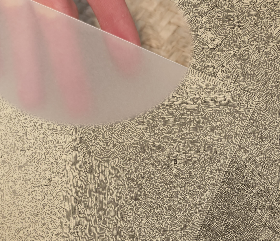 • If you will find a white hard acrylic then you are ahead one step, if you find a transparent one you will need to wet sand it with some fine grit sand paper on both sides until uniform and opaque, use water to no produce dust
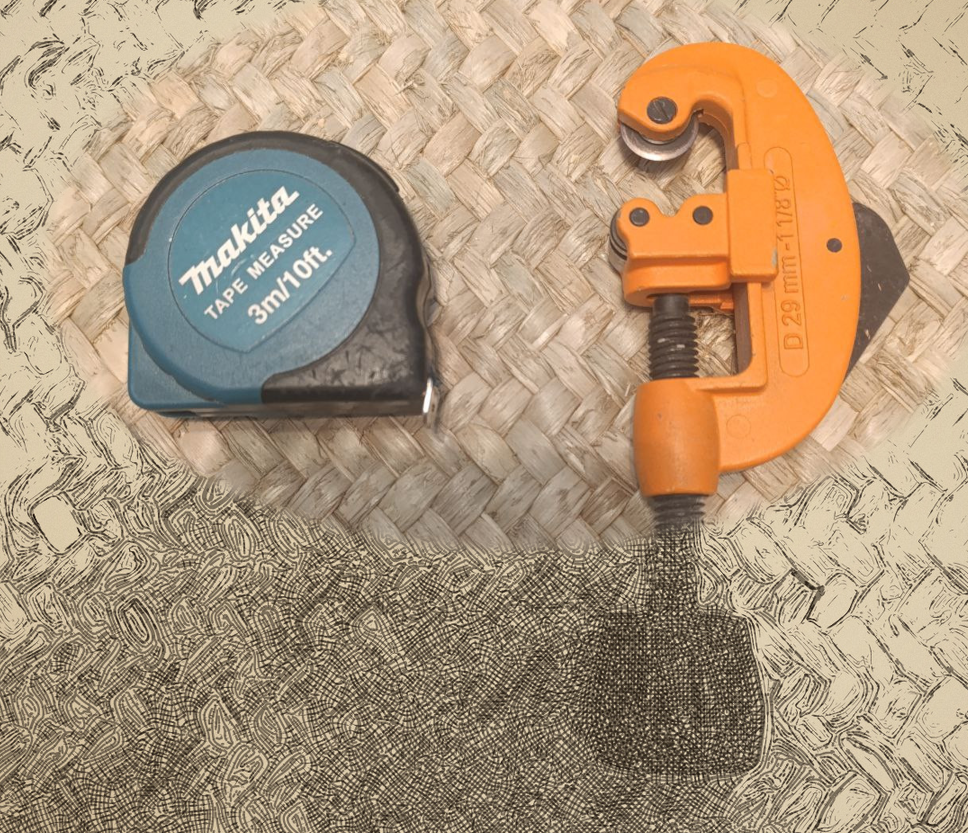
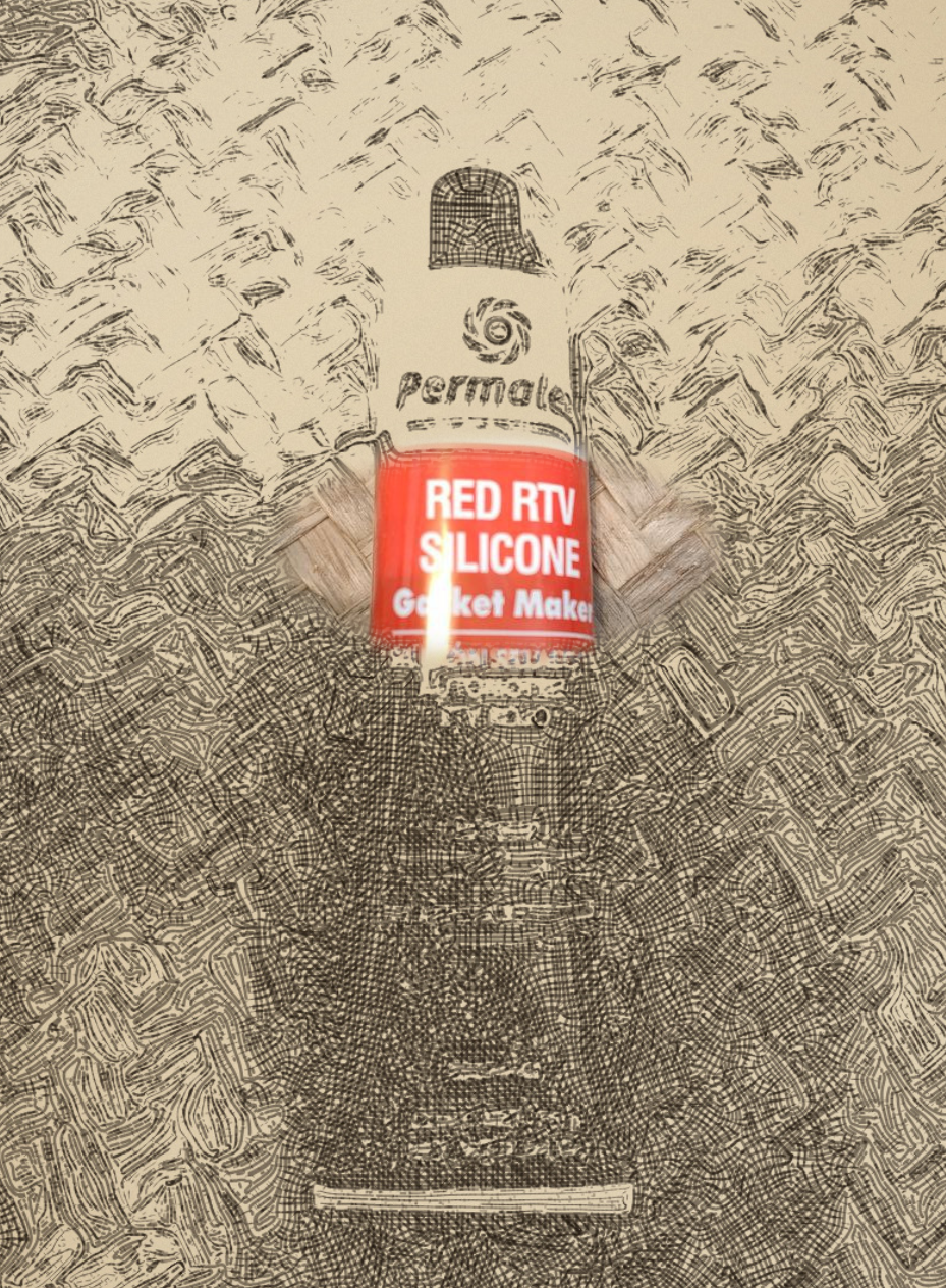
• Now is the time to mount it in a frame, to make it durable and hard, there are many solutions and approaches to this step, hopefully others will share their own solutions. Exact measuring is a must and you will need a ruler a pipe cutter, red automotive silicon and a few meters of 1/2 inch copper tube, also get four 90° joints, and four "T's" to fit the copper tube.
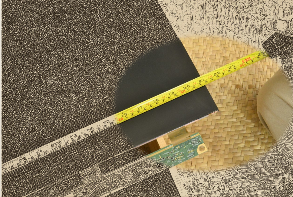
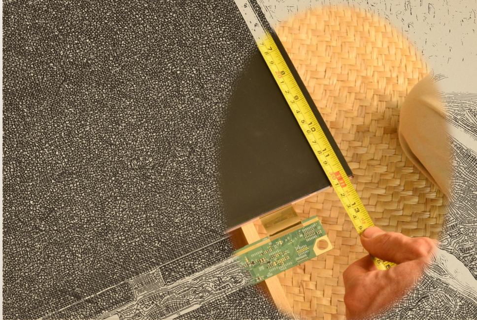
• Carefully measure the actual panel from one dimension and then from the other, be really accurate, and write this measurements, be careful with the ribbon cables, always be conscious of where your hands are
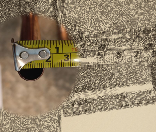
• Add all this sides of the panel to (2x height + 2x width) to the total length of your copper tube perimeter plus add 1 more meter, then cut the pipe accordingly, this has to be real precise.
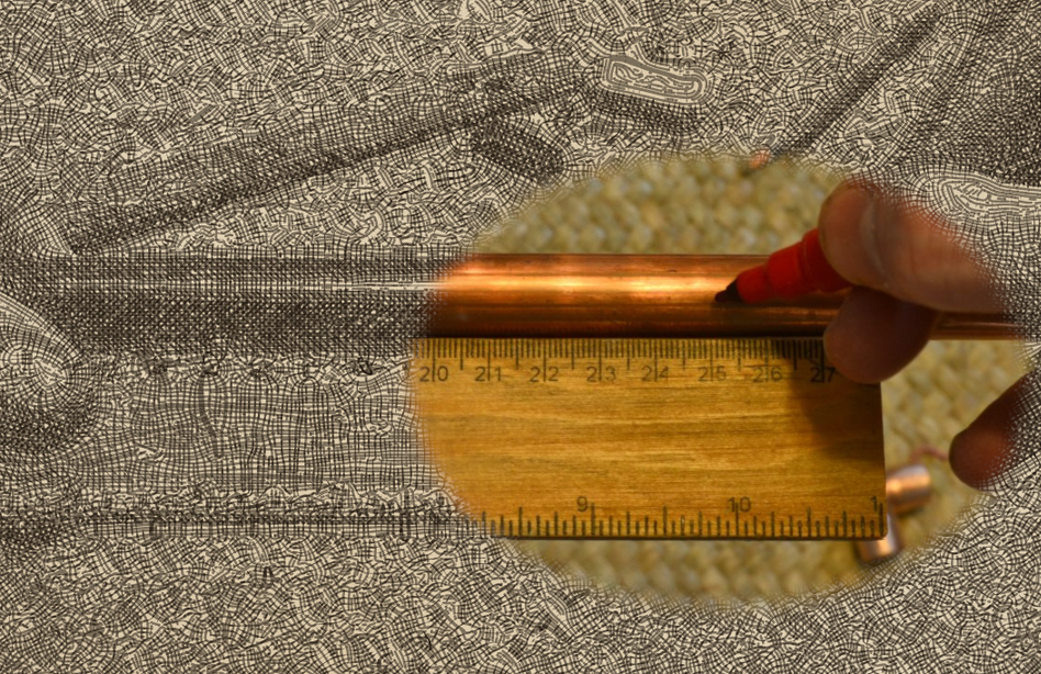
• Take this measurement and multiply it by .75 then subtract this number by the absolute length of each side of the panel, and cut the copper pipes exactly to each of the measurements with the pipe cutter.
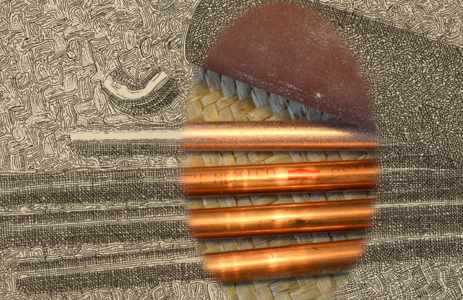
• Once you have these cut, you will need to sand them with some fine grit sand paper so the red silicon holds right, also the 90 ° angles.
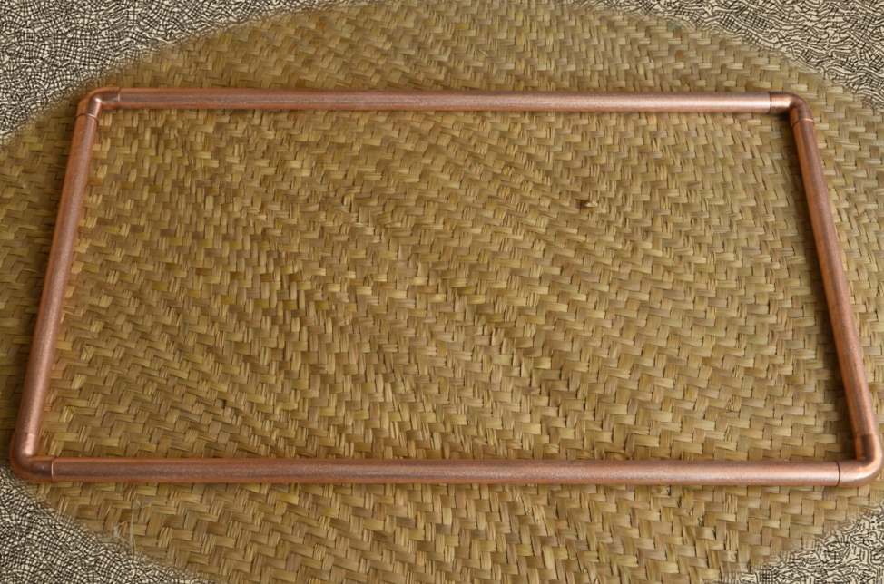
• You should end up with a frame slightly bigger than the panel when fitted tight, but do not glue anything together yet
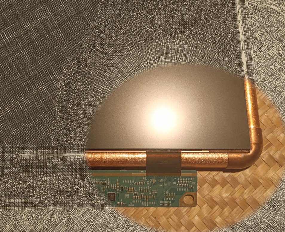
• If you carefully place the panel in the top, the edges should be around the middle of the tube if you did things right, actually bit more inside than tight in the middle to prevent shadows
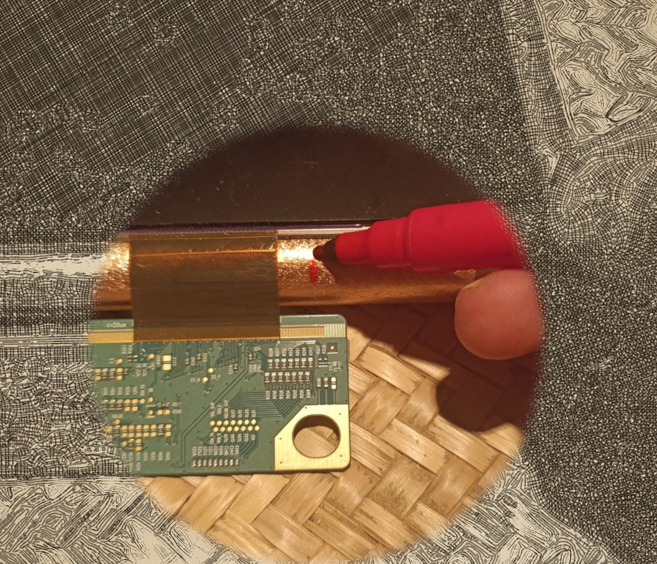
• Mark the copper tube around the end of the card, if this extends to the lateral edge of the frame, then just mark some 3cm from the edge of the bottom tube, this is where the T's will be placed, which will serve as part of the base
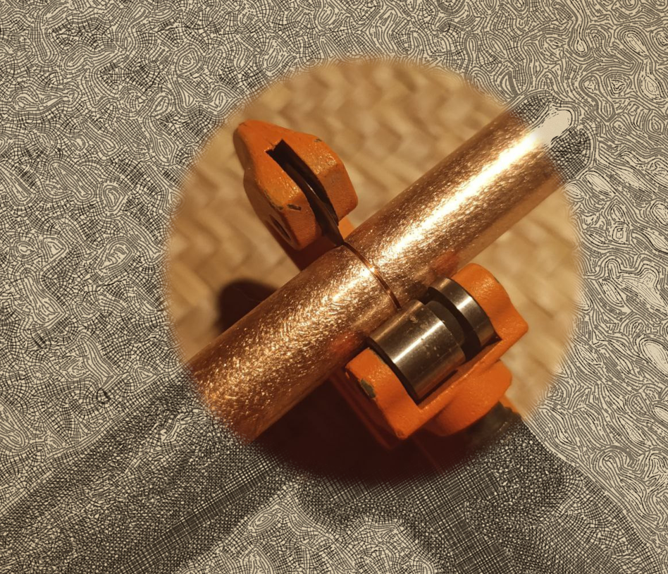
• Carefully remove the panel and put it in a safe place, the take that copper tube and cut it in the markings
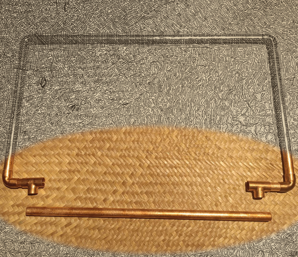
• When you put the frame back again it should look something like this, with the small cut parts fitted in the corners to the T's, but now you have noticed that the bottom tube is larger and it does not fit, so we need to make it the same size as the top
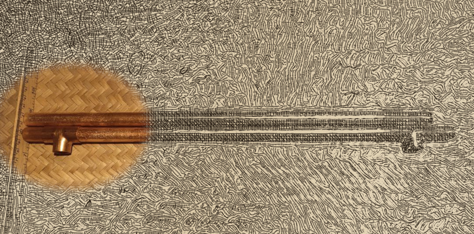
• So take both bottom and top tubes and put them side by side, nicely...
Read more »
Share your 🌶️ 📺 on ☠️ a 🌞.io
Of course, a complete steampunk incandescent monitor would also have a mechanically supplied airflow from a couple of thermoacoustic engines running on the available temperature gradient supplied by the incandescent bulb, but that's for another project.
Disclaimer: Not answering any technical prompts, please do your own fafo.