 mircemk

This time I want to describe my two DIY super powerful audio amplifiers that I made about 40 years ago. One is with a MOSFET and the other with bipolar transistors at the output. These are output amplifiers with 775mV input sensitivity, which means that they need to be connected to a preamplifier or audio mixer. At the time they were made, their purpose was to serve in discos with loudspeakers with a built-in passive crossover. I live in a tourist center - Ohrid and at that time large discos and sound systems on the beach were popular. So I had the opportunity to test them for a long time in real conditions.
First, let me describe the Mosfet amplifier.
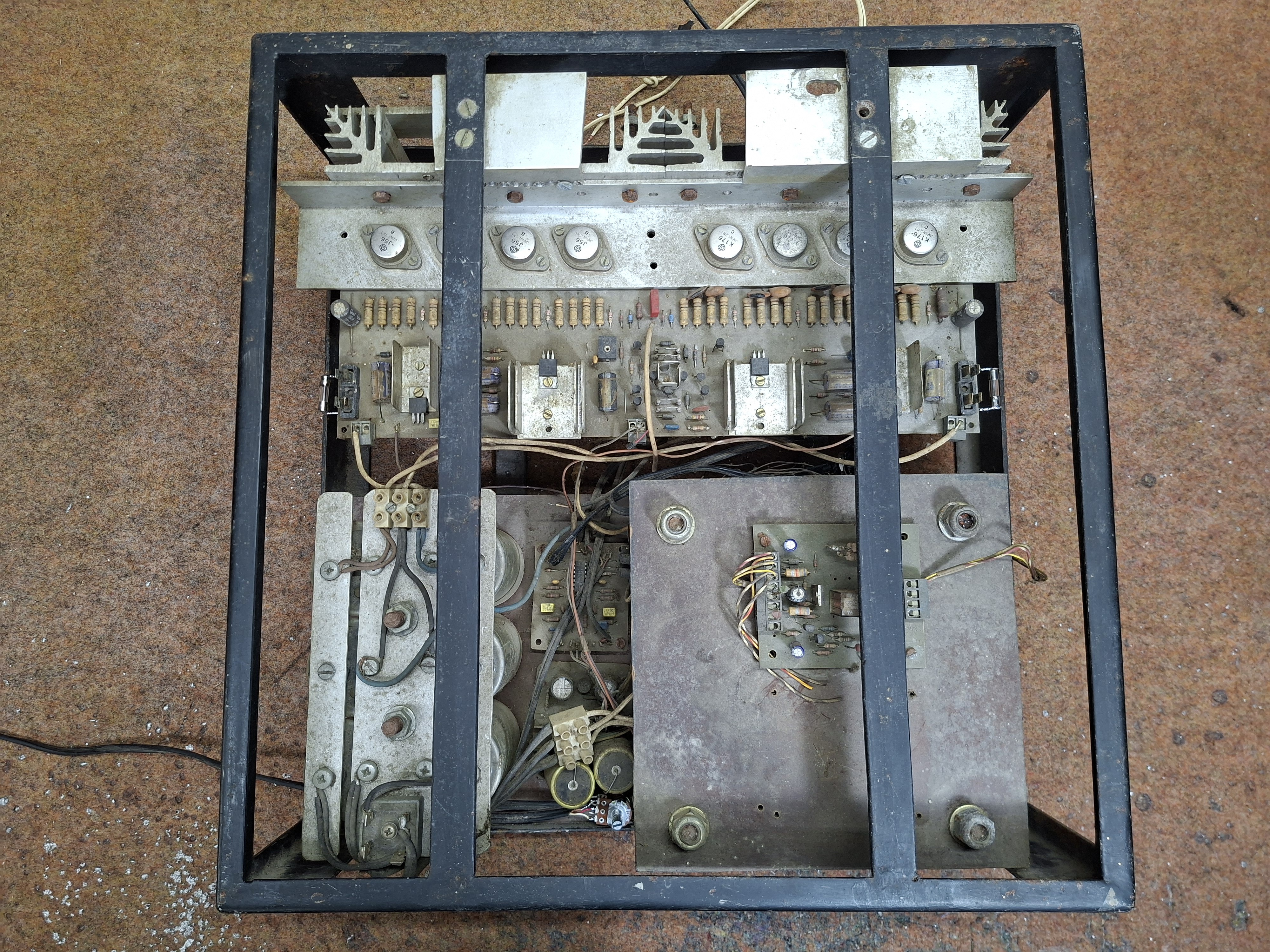
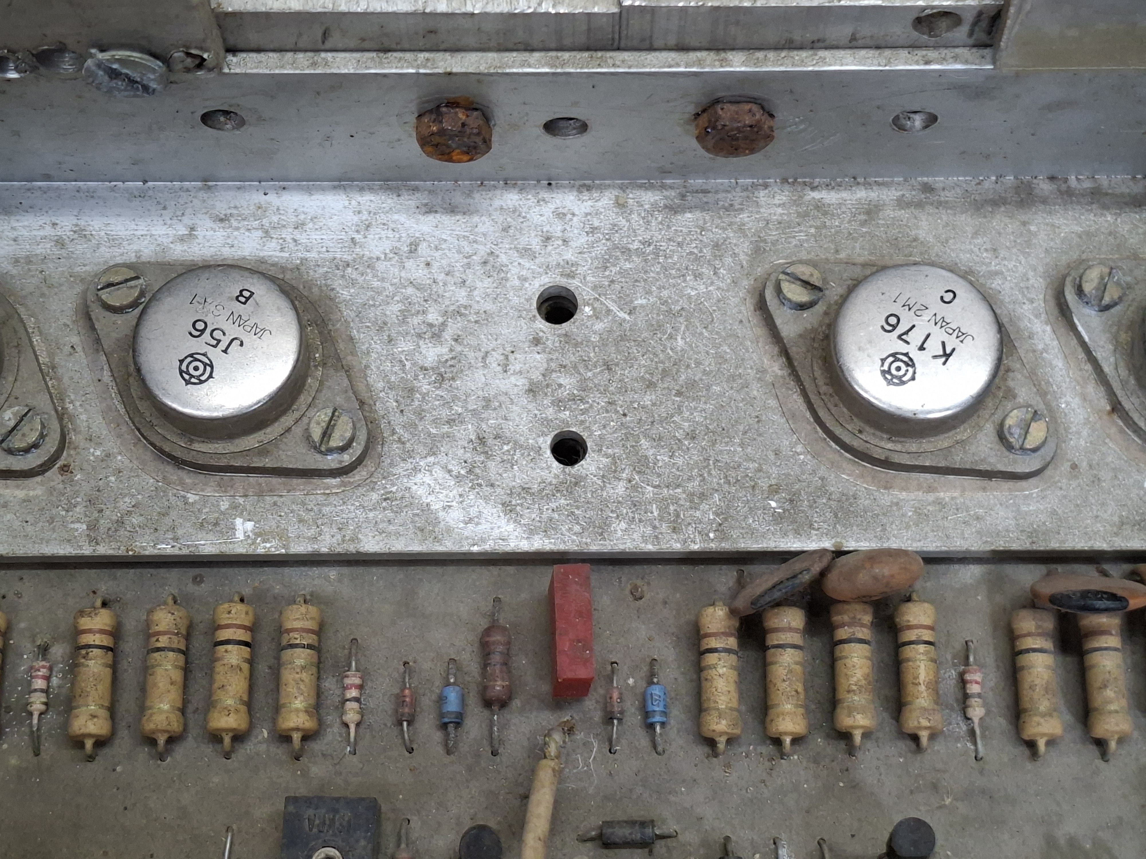
This is the most powerful amplifier ever published in the magazine Elektor to this day. Its construction is described in two parts in issues 7/1986 and 11/1986. Its output power is 2 times 500W at 4 Ohms and a full 1000W (or 1kW!) Mono at 8 Ohms in a bridged connection, measured within10Hz to 30KHz band with distortions lower than 0.01%, and a damping factor greater than 100. You will agree, these are impressive data, especially for 40 years ago. The output mosfets are of the type 2SK176 and 2SJ56 and I managed to obtain them in a neighboring country.
The same applies to the electrolytic capacitors with a large capacity of 2 times 30,000 µF / 100V, or a total of 60,000 µF. The transformer is also custom made with 2 outputs of 55V / 15Amperes, and outputs for protection and the bridge circuit of +/-12V, as well as +/- 90V for the driver stage before the output transistors. I made three identical amplifiers of this type, all of them worked on the beach, and only one of them had a blown fuse, and after replacing it, it continued to function normally. Let me just mention that all three worked "from the start" and I had no breakdowns or adverse events immediately after I made them. All three function flawlessly to this day. I currently own only this sample and I tried to put it into operation after many years. Even as you can see, I don't know where the cover and the pages are. Actually this is the first test sample, it has only one channel and its purpose was to test the power and characteristics before I made the other three. Until today it was in a basement in conditions of high humidity and dust but it still worked immediately. Only the fuse bases were oxidized, so I had to solder the fuses directly to the PCB. As you can see the wiring is poorly done, unlike the next three samples. There is not even a functional protection with a relay from direct voltage at the output.
This is the picture of second amplifier, I made it at almost the same time, right after the mosfet amplifiers and I also made three identical samples.
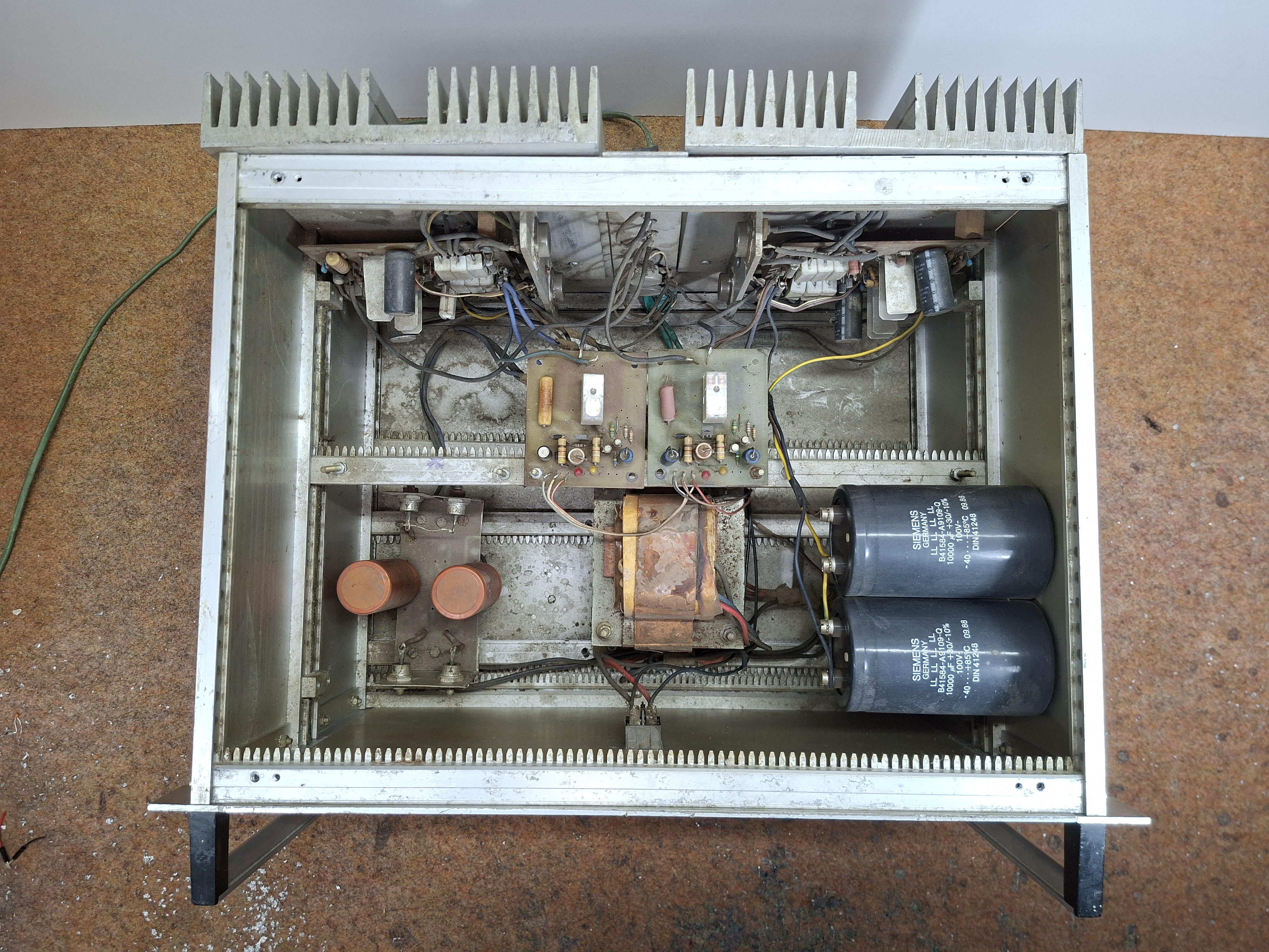
These amplifiers worked in incomparably more difficult conditions than the previous ones, in large discos, under maximum load, both on passive speakers and active systems. The source of the circuit diagram is unknown to me, in fact the owner of the company where I worked at the time brought me a nicely documented script titled "PAKEL" - Proaudio Kit Electronic, so that I could make for him a Mosfet amplifier described in it. The script contained several amplifier and preamplifier projects described in detail with circuit diagrams and PCB drawings. Just to mention that I have built all the projects from this script and they all work flawlessly. It was immediately clear that these were super-quality audio projects made with components easily available at the time.
After a long search through my old documentation, I couldn't find this script, and on the internet, I accidentally found a circuit diagram and layout of the PCB elements from the top side, just for this project, at the end of the text you can download it. Еven in today's modern era of cheap D-Class amplifiers, these old designs are superior in terms of audio quality. Guided by previous experience, my attention was drawn to a 500W audio amplifier with MJ15003...
Read more »