 svofski
Printed new wheels using slightly wet filament and had a couple of minor defects in the white ticks so I touched them up using white acrylic paint. Thought nothing of it, didn't even take a picture.
Here's what sensor reading looks like when passing the touch-up points:
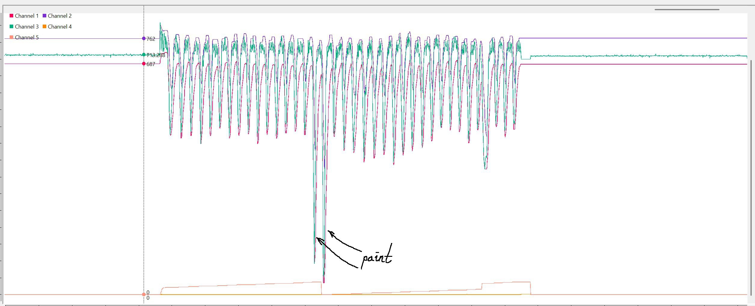
This is a great contrast and I would like to have it for all tick marks, but unfortunately my white filament seems to be rather dull from QRE1113 point of view.
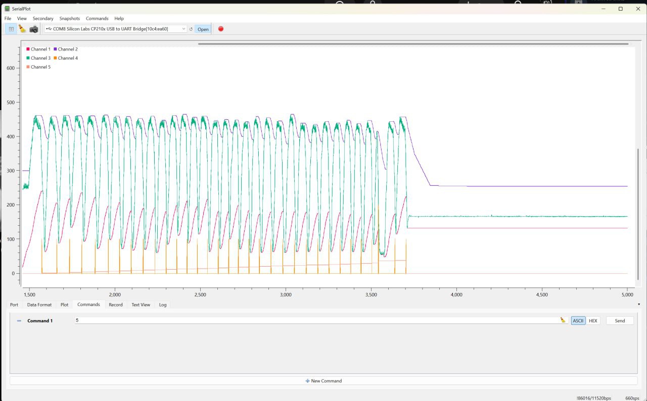
For comparison this is the regular code wheel without touch-ups (this graph is from a sensor with 200K collector resistor, so absolute values are different).
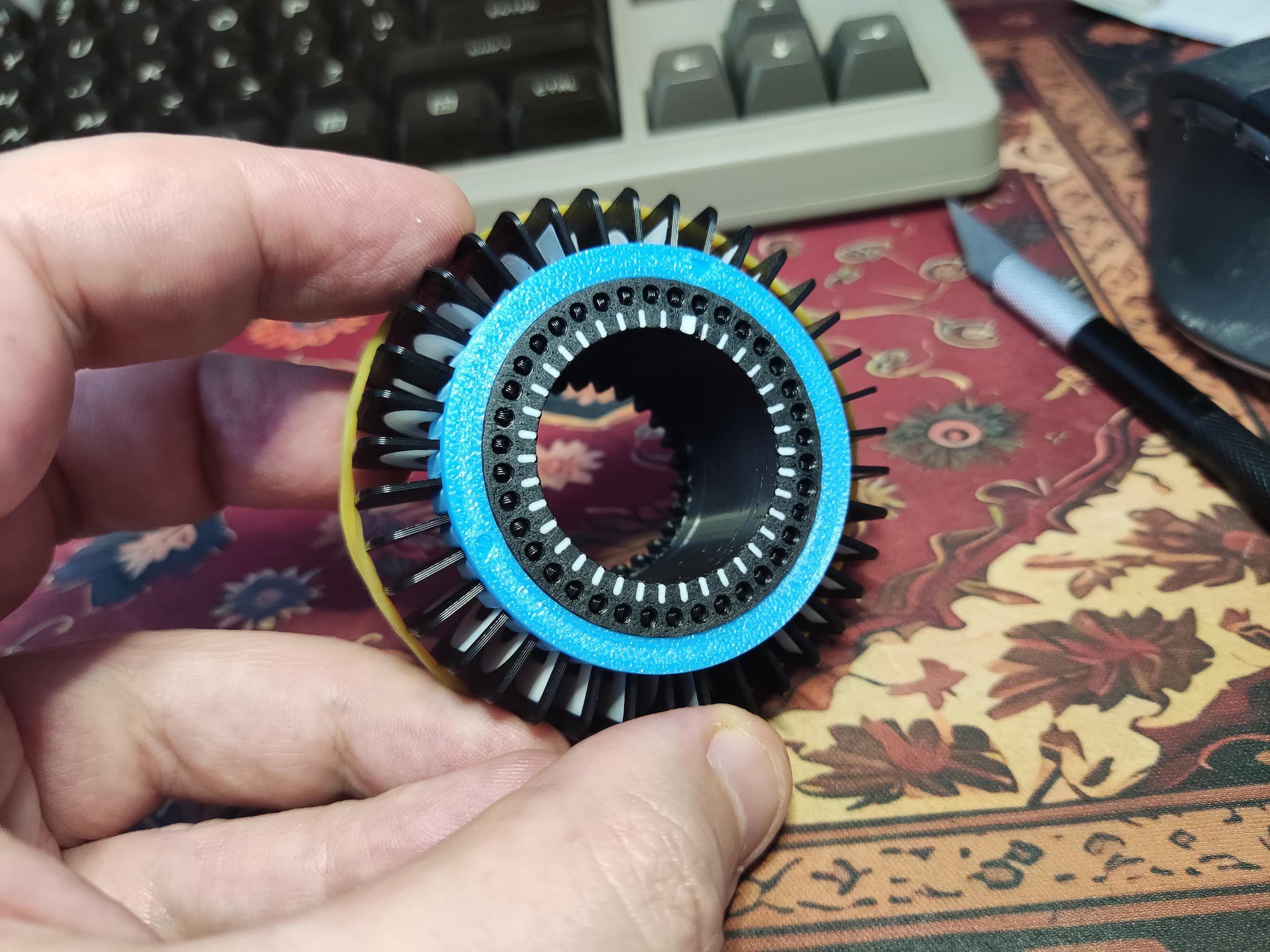
The tick marks on the code wheel. A thick one represents home position.
 Luckily my simple algorithm turned out to be robust enough to cope with irregularities. I decided to add another tunable parameter, the tracking divisor. It adjust min/max leakage rate. The larger the value, the slower the peaks decay towards the middle. It proved to be quite useful when tuning individual displays.
After just a few minor mishaps inevitable when connecting a bunch of wires I managed to tune up each display and get them all work together.
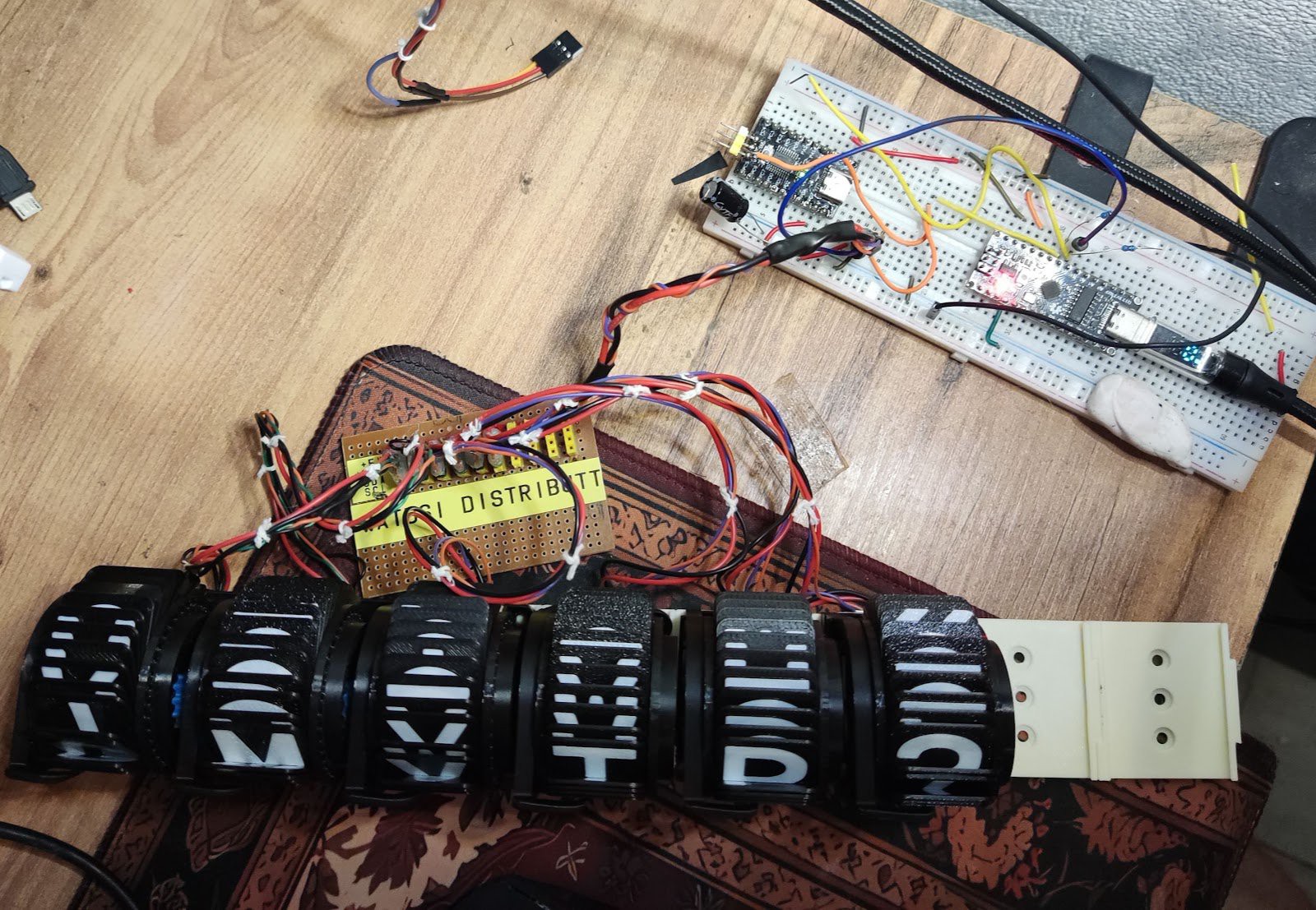
I think I2C was a good choice because it gives some flexibility and spending a bit of time to add tunable parameters definitely was worth it. It is surprising how much variance there is between individual displays. They all use same parameters and the motors are from the same bag.
A celebratory message from Father Jack:
I'm feeling almost confident enough to add 4 more characters. 10 split-flaps characters ought to be enough for everybody.
Discussions
Become a Hackaday.io Member
Create an account to leave a comment. Already have an account? Log In.