Close
0%
0%

Upgrading the Casio CA-53W

A fully programmable PCB designed to replace the brains of the iconic calculator watch by Casio. Based on Joey Castillo's Sensor Watch Pro.

Similar projects worth following
A super-duper fully open and programmable PCB for the Casio CA-53w calculator watch. Based on the awesome work of Joey Castillo, it has the same features as the Sensor Watch Pro. Imagine the possibilities with a keypad!

  • Drop-in replacement PCB for the Casio CA-53W
  • Open source hardware & firmware with many applications ("faces")
  • ATSAML22N18A microcontroller
  • LIS2DW12 accelerometer on board
  • Loud piezo buzzer (using PAM8904)
  • Designed to be as affordable as possible (2 layer PCB, no via smaller than manufacturer specifications)
  • Temperature & light sensor on board
  • Long battery life (should be 1-2 years)
  • Full support for LCD
  • Integrated USB connector (for Micro USB cable, as seen on Sensor Watch)

  • Sourcing parts and working on firmware

    Evelien Dekkers4 days ago 0 comments

    Good day everyone,

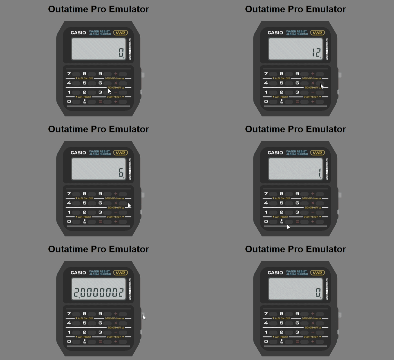
    Some notable progress has been made on this project. First of all, I got a calculator function working in the firmware! Took me a while to be honest.

    RE: Choices to make: FPC connector

    The 9 pin connector... In the previous project log, I explained how there would be 0.1mm of space between the connector and the module housing. When I looked closer at the datasheet, this dimension of 0.9mm had a tolerance of 0.1mm, meaning that it could be anywhere from 0.8mm to 1.0mm. That meant that unfortunately, I would not be able to fit this connector on the PCB.

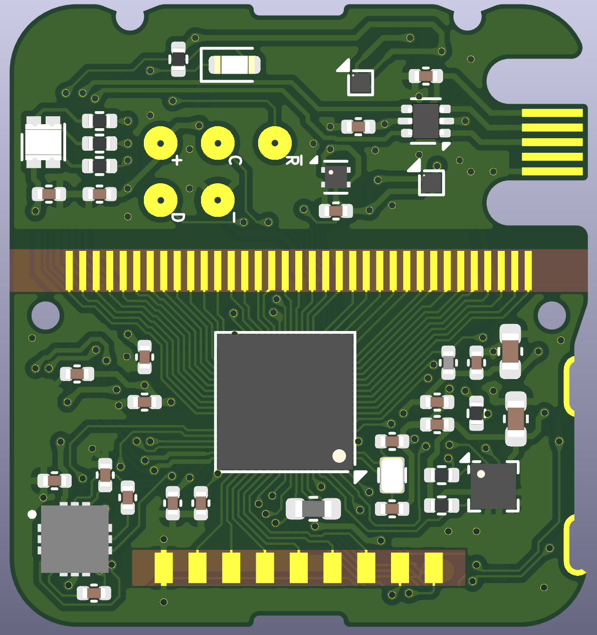
    I have decided it will go. Instead, I have put the accelerometer on the main board. This will make the project more affordable and less complicated. Someone suggested to me to use a magnetometer+accelerometer module, and while I'd love to, this part was too tall at 1.0mm. Here it is, where the 9-pin connector used to be. (Bottom right)


    Sourcing parts: Microcontroller

    The biggest obstacle with this project is the microcontroller. While the Sensor Watch project uses the 64-pin ATSAML22J18A, this project uses a very similar chip with even more pins (it just wasn't enough!). My eyes were set on a chip that is virtually identical, but just has more pins. The ATSAML22N18A-CFUT. A BGA chip with 100 pins!

    This project is my first time using a BGA chip for anything, and it's not that complicated to design around. What I really needed to be mindful of, because of the tiny footprint of this PCB, is the order in which tracks are routed. I can't have hundreds of vias next to each other all going in different directions. It simply wouldn't fit on the board. 

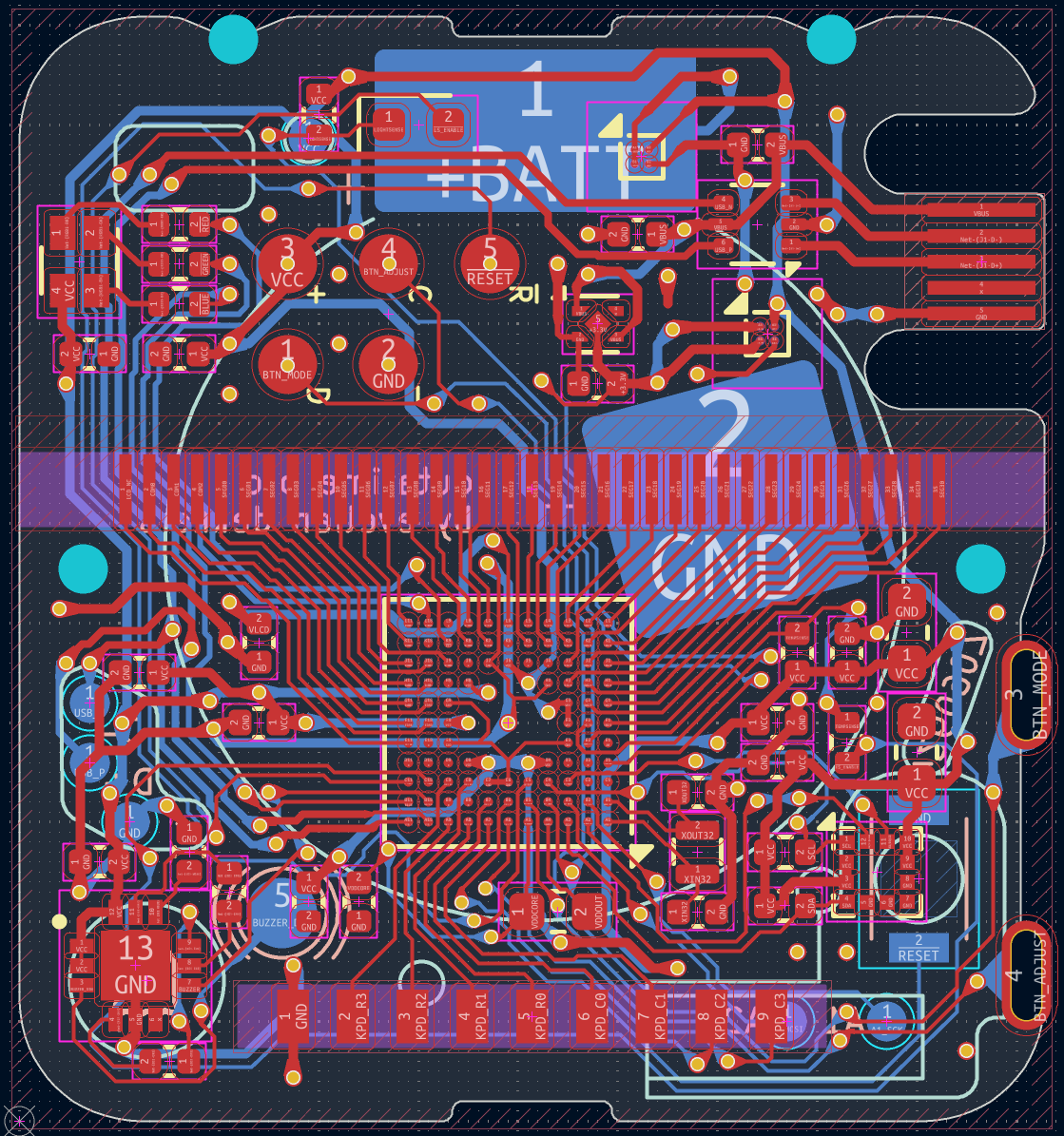
    Take a look at this:

    What you see here is the board, viewed from the top, with the bottom copper layer visible as well. The neat thing about making a design from scratch is that you can choose pins and component placement very efficiently. The display connections are all neatly routed next to each other, going to corresponding pins on the microcontroller.

    This also means that this is probably the smallest high pin count chip that will fit. Again, there are many design constrains in this module.

    When looking at getting PCBs made, my choice was pretty much set: JLCPCB. They have grown to be the biggest player in the PCB manufacturing market. And they have easy to use assembly services. All parts were in stock, except for the most important one.. the microcontroller. So I went looking, and it turns out that not one single authorized distributor has these in stock. Ironically they do have the larger 100 pin version of this chip, but that wouldn't work in this design. It's too tall!

    They are in stock at Microchip, and JLCPCB has a "consign parts" feature. I send parts to them, they keep them for me and I would be the only person who could use those parts for their SMT assembly services. Great! Except, I need to buy 50 or more! I didn't feel like I had much of a choice though, and because I'm really sure about using this chip, I went ahead and bought 50 ATSAML22N18A-CFUT chips.

    Sometimes difficult or painful choices need to be made in design. Sometimes choices are easy and valueable. Such as the other part that couldn't be sourced.

    Sourcing parts: Inductor

    The second issue was the inductor. The original Casio modules presumably use a part from Panasonic, the ELT-3KN004B, a 14MH inductor. Inductors however, are quite big, and these ones made by Panasonic are not made anymore. So I went looking for a replacement, finding none that would fit. Digikey has this nice write-up about the function of this part: Increasing the Output of a Piezo Transducer Buzzer

    Without it, the buzzer would be close to inaudible. After what felt like an afternoon of Google searches, I found the ultimate replacement: PAM8904. A piezo sounder driver that can deliver up to 18v peak-to-peak. Which is exactly what I need! This 18 volts is achievable when using both output pins. In the design of...

    Read more »

  • Choices to make: FPC connector

    Evelien Dekkers09/04/2026 at 14:25 0 comments

    Hello! Welcome to the first update log on this project. Progress has been good the past couple of weeks.

    While the PCB design has been finished, work on the firmware has started. So far the clock face, stopwatch face, alarm face, and the settings face have been ported over. I am working on adding more!

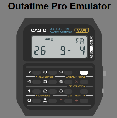
    The emscripten emulator running the actual firmware. Keypad input is fully functional! (Pressing divide on the clock face shows the year, month and day.)

    There is one issue with the design:

    Cost.

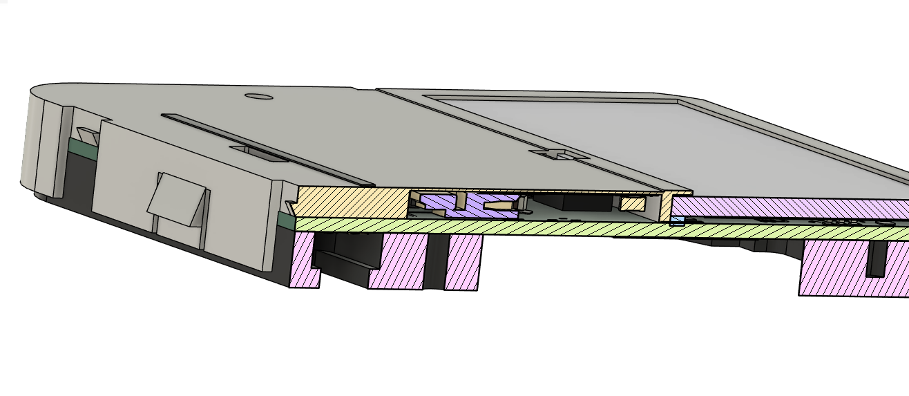
    Let me explain: the main PCB has a 9-pin connector, just like the PCB that inspired this project. However, the connector is 0.9mm tall, where the internal height in the module is 1.00mm. That means there is 0.1mm of room between the module case and the connector. Which is, really, really tricky. Besides: the prototyping cost for the flex PCBs drives the total prototyping cost way up! Actually, it doubles it. For production runs, it wouldn't be as big of a factor, because multiple accessory boards would fit in a panel.

    So I can either remove the connector and put the accelerometer on the main PCB, reducing cost and complexity, OR keep it, but spend twice the amount on prototyping cost, have the uncertainty of the connector not fitting in the case, and increase production complexity. After all, there would be not one but two products.

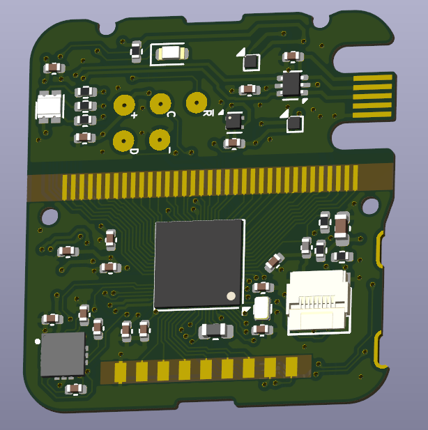
    To give you an idea:

    In purple: the Hirose FH35C-9S-0.3SHW connector

    The component heights and internal clearances are not completely right (near the display) on this 3d model, but it gives you a good visual of the problem at hand.

    While I will be thinking about this, feedback is very welcome. How do you use the 9-pin connector on your watch?

View all 2 project logs

Enjoy this project?

Share

Discussions

freefuel wrote 4 days ago point

Awesome work, now please do the Casio DBA watch next! 

  Are you sure? yes | no

Similar Projects

Does this project spark your interest?

Become a member to follow this project and never miss any updates