• Choices to make: FPC connector

    Evelien Dekkers2 hours ago 0 comments

    Hello! Welcome to the first update log on this project. Progress has been good the past couple of weeks.

    While the PCB design has been finished, work on the firmware has started. So far the clock face, stopwatch face, alarm face, and the settings face have been ported over. I am working on adding more!

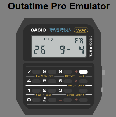
    The emscripten emulator running the actual firmware. Keypad input is fully functional! (Pressing divide on the clock face shows the year, month and day.)

    There is one issue with the design:

    Cost.

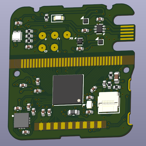
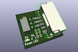
    Let me explain: the main PCB has a 9-pin connector, just like the PCB that inspired this project. However, the connector is 0.9mm tall, where the internal height in the module is 1.00mm. That means there is 0.1mm of room between the module case and the connector. Which is, really, really tricky. Besides: the prototyping cost for the flex PCBs drives the total prototyping cost way up! Actually, it doubles it. For production runs, it wouldn't be as big of a factor, because multiple accessory boards would fit in a panel.

    So I can either remove the connector and put the accelerometer on the main PCB, reducing cost and complexity, OR keep it, but spend twice the amount on prototyping cost, have the uncertainty of the connector not fitting in the case, and increase production complexity. After all, there would be not one but two products.

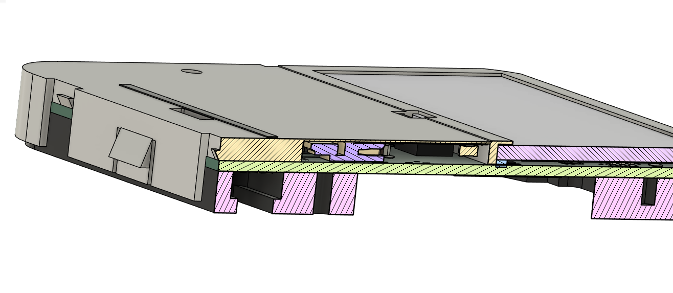
    To give you an idea:

    In purple: the Hirose FH35C-9S-0.3SHW connector

    The component heights and internal clearances are not completely right (near the display) on this 3d model, but it gives you a good visual of the problem at hand.

    While I will be thinking about this, feedback is very welcome. How do you use the 9-pin connector on your watch?