 DIY GUY Chris

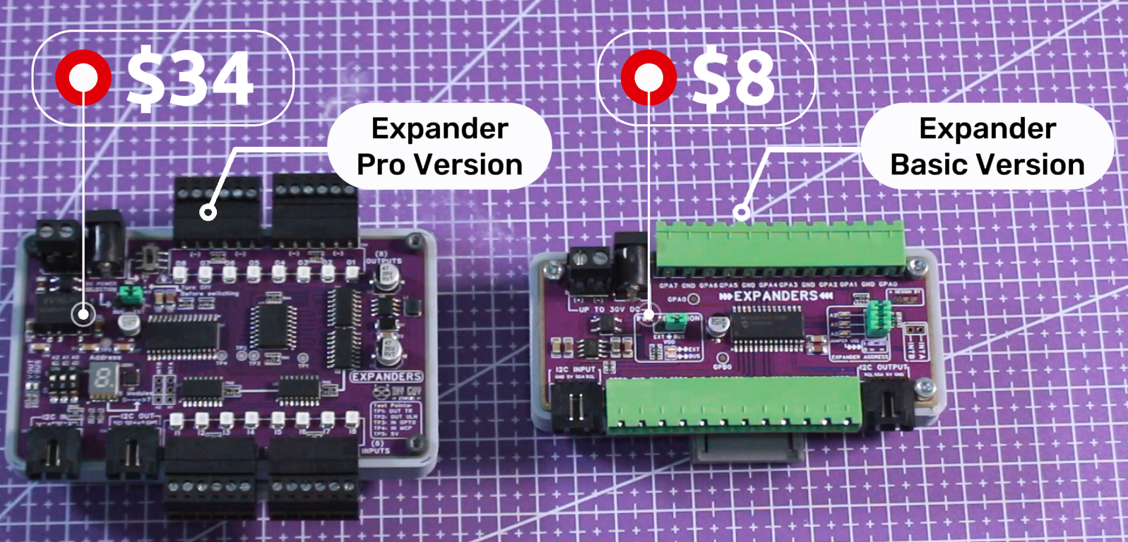
Supplies
Main ICs:
- MCP23017 (I²C I/O Expander)
Power:
- MB2S (Bridge rectifier)
- 78L05 (Voltage regulator)
- DC Jack connector
- Screw terminal (2-pin)
PCB & Assembly:
- 2-layer PCB (100×40mm)
- SMD components (resistors, capacitors, LEDs)
- 5mm terminal blocks (WJ2EDGK-5.08-12P-14-00A)
- 3-pin headers for jumpers
- I²C connectors (4-pin, 2.54mm)
Optional:
- Arduino UNO (for testing)
- I²C cables
- Soldering tools (hot plate, iron, tweezers)
Schematic Design
Design the circuit in Altium starting with the power entry. Use a bridge rectifier (MB2S) for reverse polarity protection, followed by a 78L05 linear regulator to step down voltage to 5V.
The MCP23017 connects to the I²C bus. Its 16 GPIO pins are directly connected to terminal blocks, no optocouplers or ULN2803A driver needed for this basic version.
For address selection, use three jumpers connected to the A0, A1, and A2 pins. Three LEDs show the binary address (0-7). Add 1kΩ resistors for the LEDs and 4.7kΩ pull-up resistors for the I²C lines.
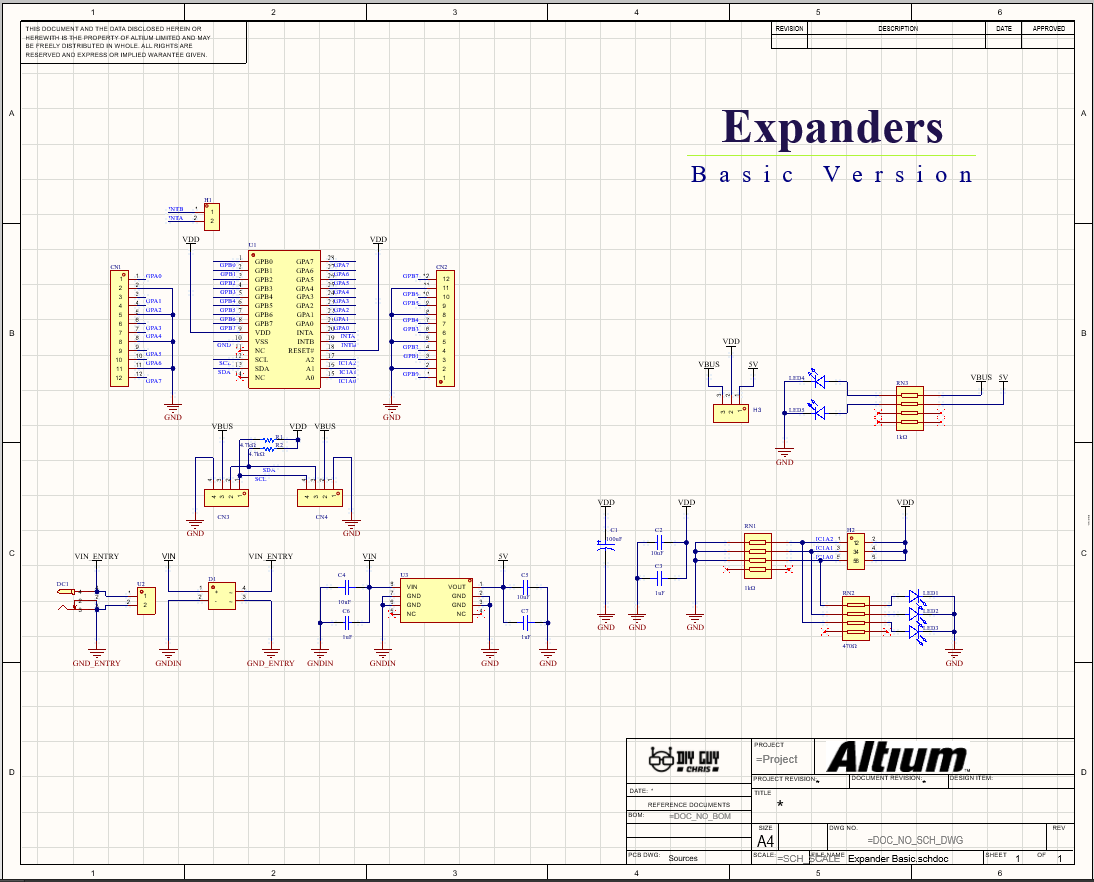
Key changes from industrial version:
- Removed ULN2803A, optocouplers, 7-segment display, BCD driver, slide switches
- Replaced with 78L05 regulator, jumpers, and binary LEDs
- 15 fewer components = simpler and cheaper!
PCB Layout
Route a 2-layer PCB measuring 100×40mm—this fits perfectly in the 100×100mm $2 special offer from JLCPCB.
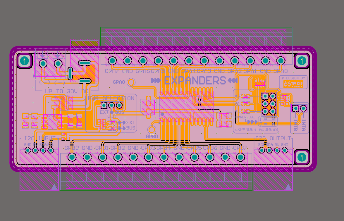
Layout improvements:
- Power entry: Top left corner (screw terminal + DC jack)
- I²C IN: Bottom left corner
- I²C OUT: Bottom right corner (fixes daisy-chaining issue from industrial version)
- GPIO terminals: Along top and bottom edges
- Address jumpers & LEDs: Grouped together for easy access
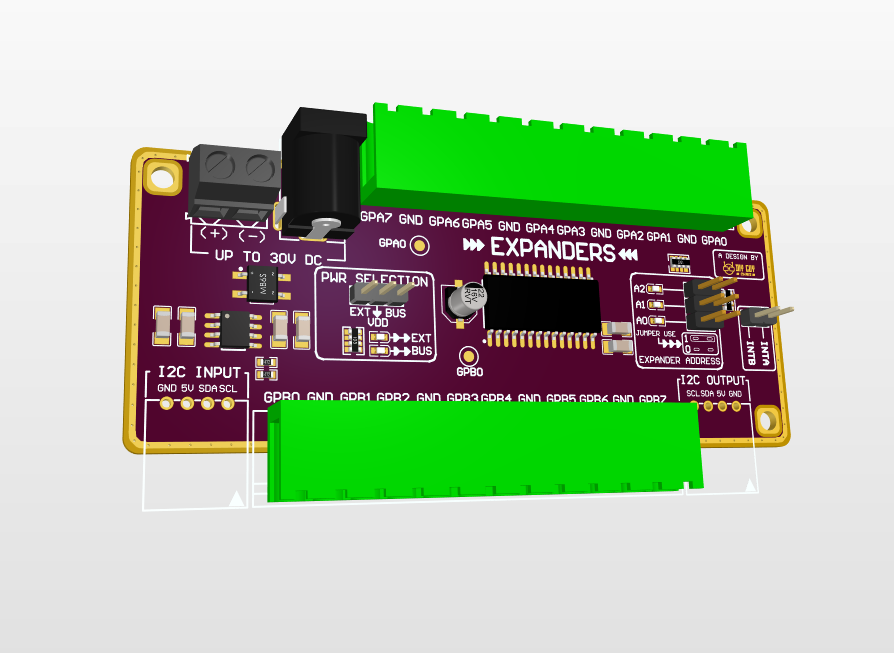
Keep traces short and use a ground pour on the bottom layer. Place decoupling capacitors (100nF) near the MCP23017 VDD pin.
Export Gerber files and upload them to JLCPCB for manufacturing.
Assembly
SMD Assembly (Hot Plate / Reflow):
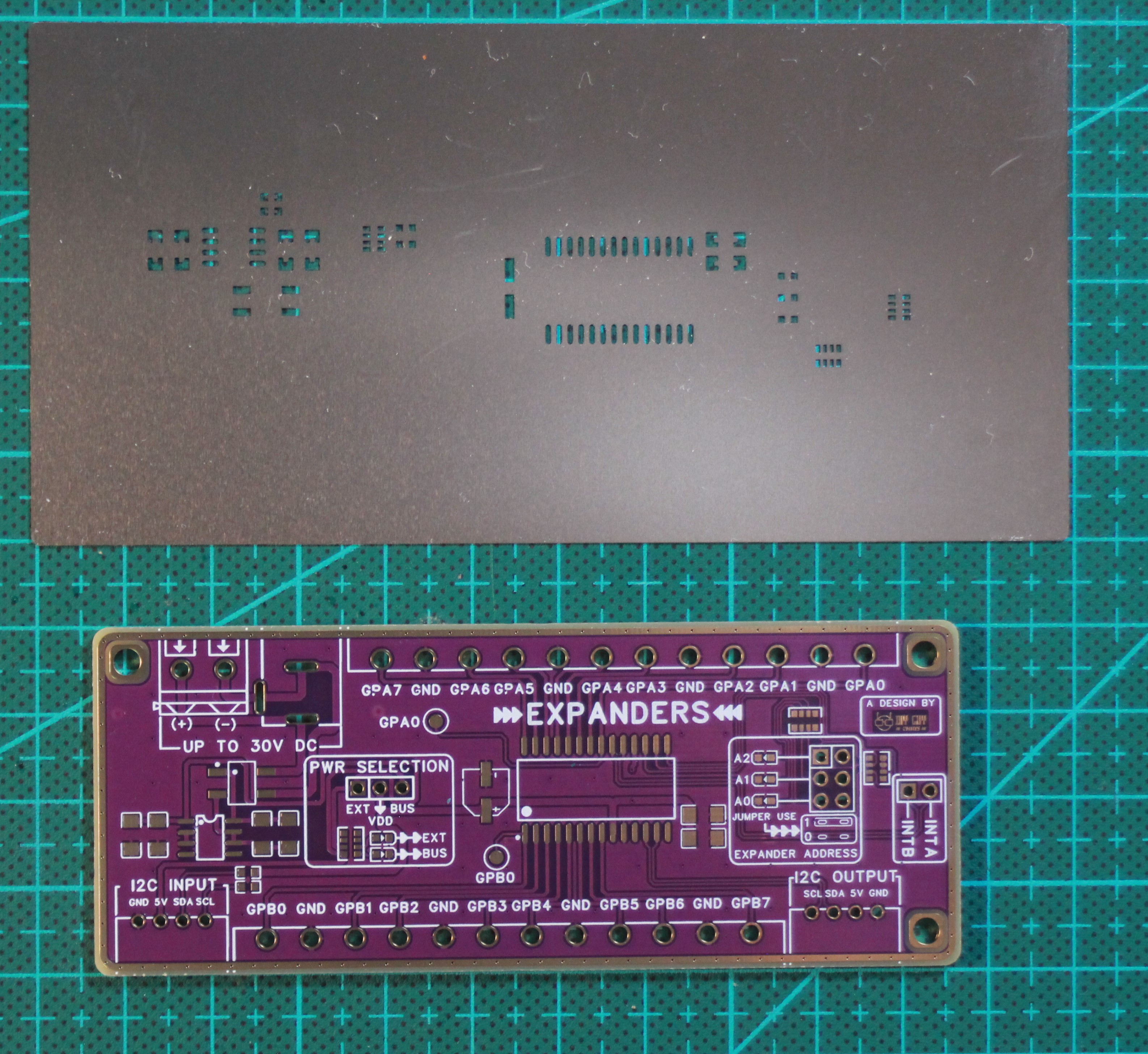
- Align the stencil on the PCB and apply solder paste evenly
- Place SMD components starting with the smallest (0603 resistors and capacitors)
- Place the MCP23017 IC last, paying attention to pin 1 orientation
- Reflow on a hot plate at 245°C peak temperature
- Inspect under a microscope for solder bridges or cold joints
Through-Hole Assembly:
- Insert the 5mm terminal blocks, DC jack, and 4-pin headers
- Solder each pin with a temperature-controlled iron
- Insert the jumpers and any remaining through-hole parts
- Trim excess leads and clean the board with isopropyl alcohol
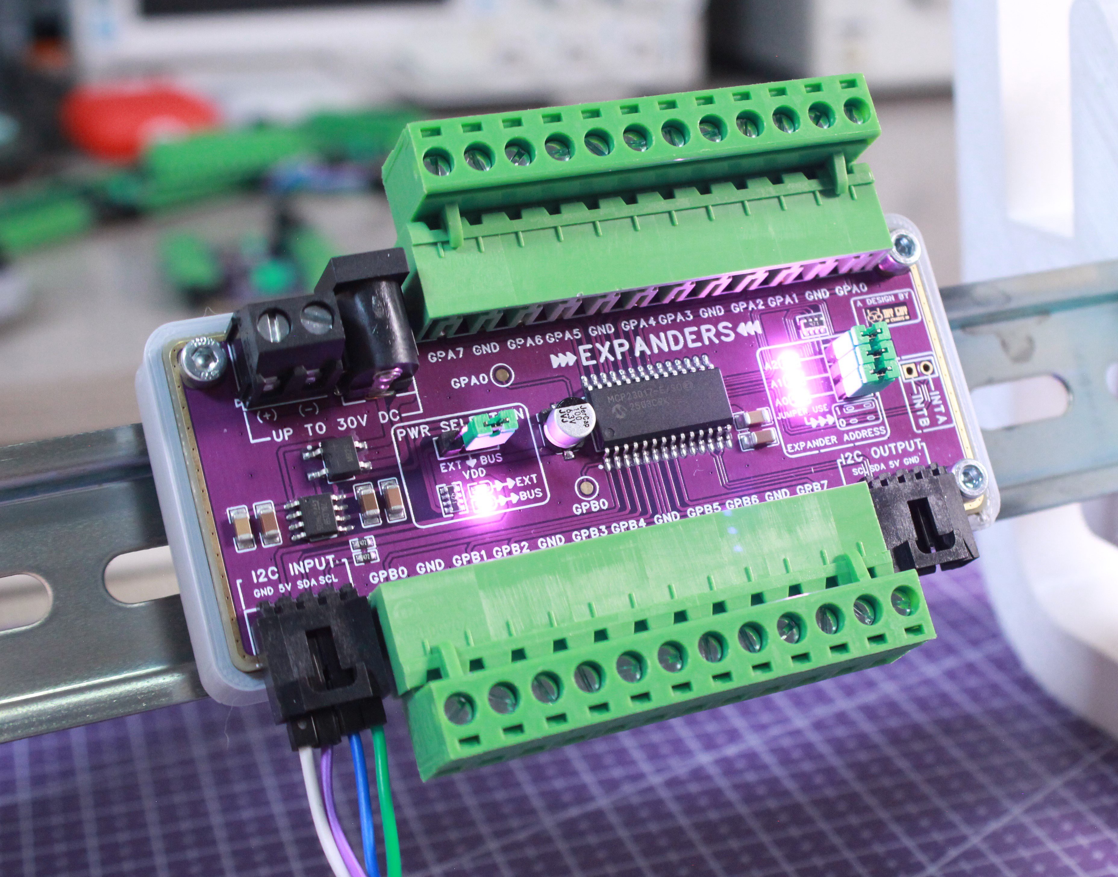
Note: The 5mm terminal blocks are much easier to wire than the 3.5mm ones used in the industrial version—perfect for beginners!
Testing & Chaining
Address Setup:
- Set the I²C address using the three jumpers (A0, A1, A2)
- Jumper ON = Logic 0, Jumper OFF = Logic 1
- Address = (A0 × 1) + (A1 × 2) + (A2 × 4)
- Verify the address on the binary LEDs
Basic Test:
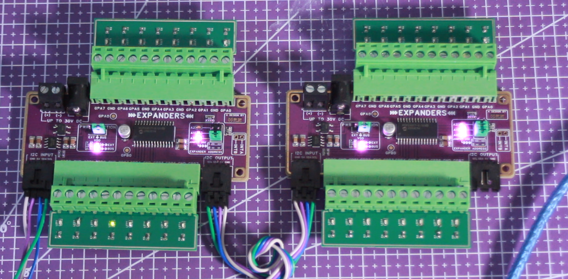
- Connect the I²C port to an Arduino (SDA, SCL, VCC, GND)
- Upload the test sketch from the GitHub repository
- Connect the testing board with LEDs to the terminal blocks
- The outputs should cycle from GPIO 1 to GPIO 16
Chaining Test:
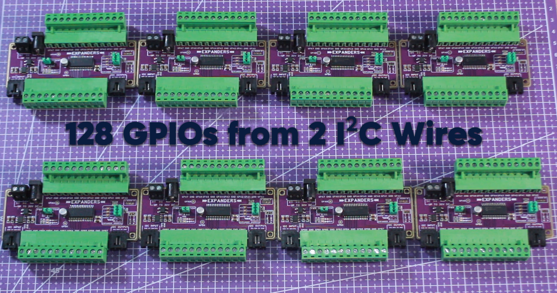
- Set a unique address for each module (e.g., 1 and 3)
- Connect I2C_OUT of the first module to I2C_IN of the second
- Update the Arduino code to control both addresses
- The outputs should cycle from GPIO 1 to GPIO 32
Download Files
- GitHub Repository: https://github.com/BEEMB/Basic-GPIO-Expander-MCP23017
- Gerber Files: https://github.com/BEEMB/Basic-GPIO-Expander-MCP23017/tree/main/Hardware/GERBER
- Schematic: https://github.com/BEEMB/Basic-GPIO-Expander-MCP23017/blob/main/Hardware/Schematic/Schematic.pdf
- Arduino Test Code: https://github.com/BEEMB/Basic-GPIO-Expander-MCP23017/tree/main/Software