 Akshay Jain

LoRa is designed for long-range, low-power wireless communication where only small amounts of data need to be transmitted. Instead of continuously streaming information, the system sends short packets containing sensor readings, commands, status information, or other application data.
The RYLR999 handles the actual LoRa radio communication, while the Arduino communicates with the module through a UART interface. The module can be configured and controlled using AT commands, so the Arduino does not need to implement the LoRa radio protocol itself.
In this project, the communication path is essentially:
Arduino UNO → UART → RYLR999 → LoRa wireless link → RYLR999 → UART → Arduino UNO
The responder processes the received message and can send a reply using the same communication path.
Why LoRa?
LoRa is particularly useful when the application requires considerably more range than technologies such as Bluetooth or conventional Wi-Fi can provide, while still transmitting relatively small amounts of data.
LoRa uses Chirp Spread Spectrum (CSS) modulation. The transmitted information is encoded into frequency-swept chirps, which improves resistance to noise and allows the receiver to detect relatively weak signals. This contributes to LoRa's long-range capability.
Depending on the environment, antenna, frequency, radio settings, and other conditions, LoRa links can reach several kilometers. The technology is therefore well suited to applications where low data rate and long range are more important than bandwidth.
RYLR999 Module
The REYAX RYLR999 Lite combines LoRa communication with 2.4 GHz Bluetooth Low Energy (BLE) functionality. The module provides separate UART interfaces for the LoRa and BLE subsystems.
For LoRa communication, the module supports a frequency range of 820–960 MHz and an output power of up to +30 dBm (1 W). Its LoRa transmit current is approximately 650 mA, while receive current is around 15.5 mA. The specified sleep-mode current is approximately 1.25 mA, with deep-sleep current around 18.2 µA.
The module operates from a regulated 4.75–5.25 V supply, but its digital I/O uses 3.3 V logic levels. This is an important consideration when connecting it directly to a 5 V Arduino UNO.
Arduino Interface
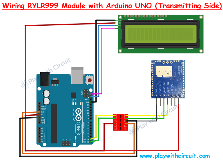
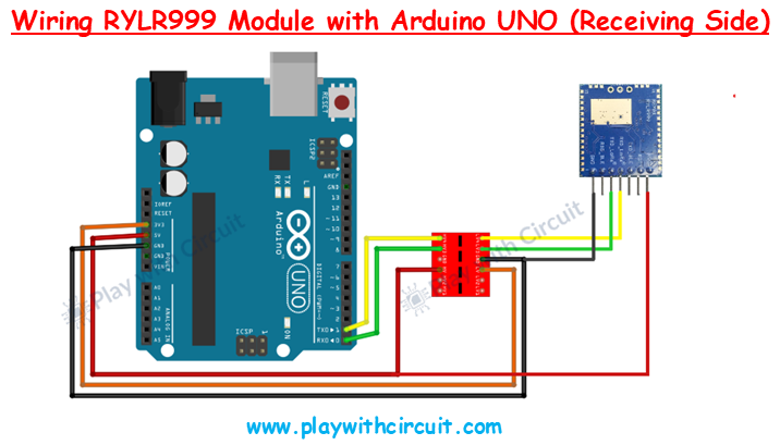
The RYLR999 communicates with the Arduino through its LoRa UART pins. The Arduino's TX line connects to the module's RXD_LoRa, while the module's TXD_LoRa connects to the Arduino's RX line.
Because the Arduino UNO uses 5 V logic and the RYLR999 uses 3.3 V digital I/O, a bidirectional logic-level converter should be used between the UART signals. The module should also have a regulated supply within its specified voltage range.
The basic power connections are straightforward: the RYLR999 VDD connects to the appropriate regulated 5 V supply, while its GND is connected to the Arduino ground.
Initiator and Responder
The two nodes have slightly different roles.
The initiator node is responsible for generating and transmitting the request message. An optional 16×2 I2C LCD can be connected to this Arduino to display communication or transmission status.
The responder node continuously monitors the RYLR999 for incoming data. When the expected message is received, the Arduino can generate a response and send it back through its RYLR999 module.
This simple request-and-response structure provides an easy way to verify that both LoRa modules are communicating correctly.
RYLR999 Pin Interface
The module provides seven main pins. VDD is the power input, while GND provides the common ground connection. RST is an active-low reset input.
The RXD_LoRa and TXD_LoRa pins form the UART interface used for LoRa communication and AT commands. The module also provides RXD_BLE and TXD_BLE pins for its Bluetooth Low Energy subsystem.
The separation between the LoRa and BLE interfaces also allows the RYLR999 to be used for applications where BLE acts as a local interface and LoRa provides the longer-range communication link....
Read more »