 gulliverrr
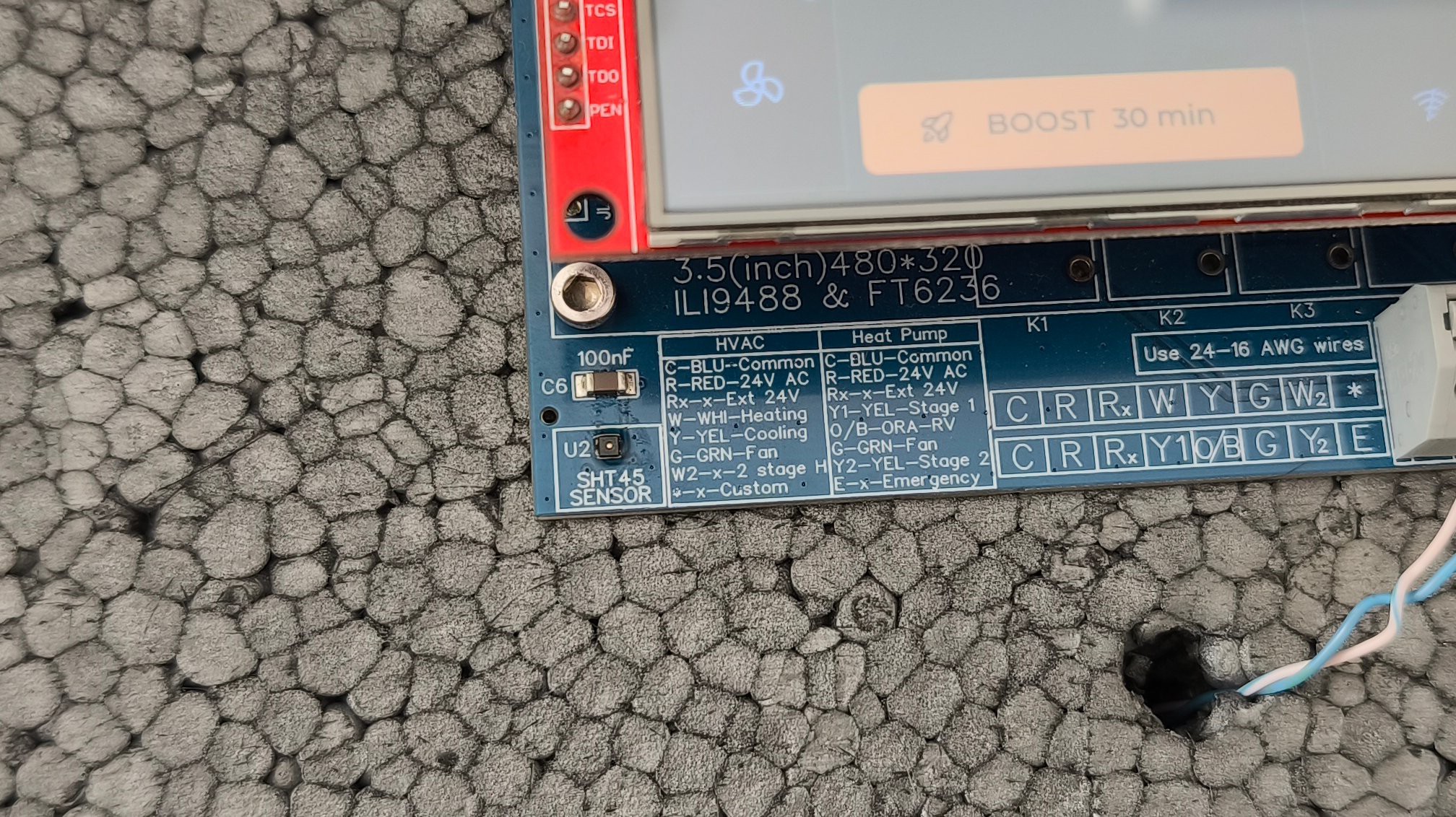
During testing of the previous Hestia32 XIAO HVAC PCB, I found an unexpected problem: the SHT45 temperature sensor was consistently reading around 6-7°F higher than the actual ambient temperature after the board had been running for a while.
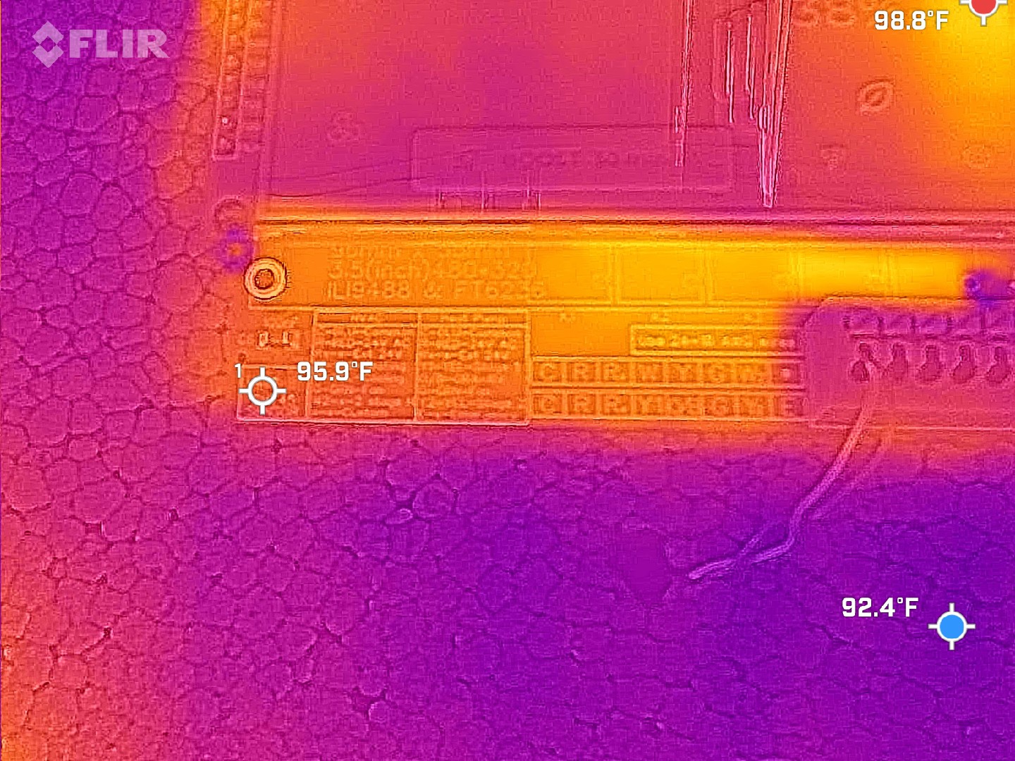
The cause turned out to be heat traveling through the PCB copper planes from other components towards the sensor.
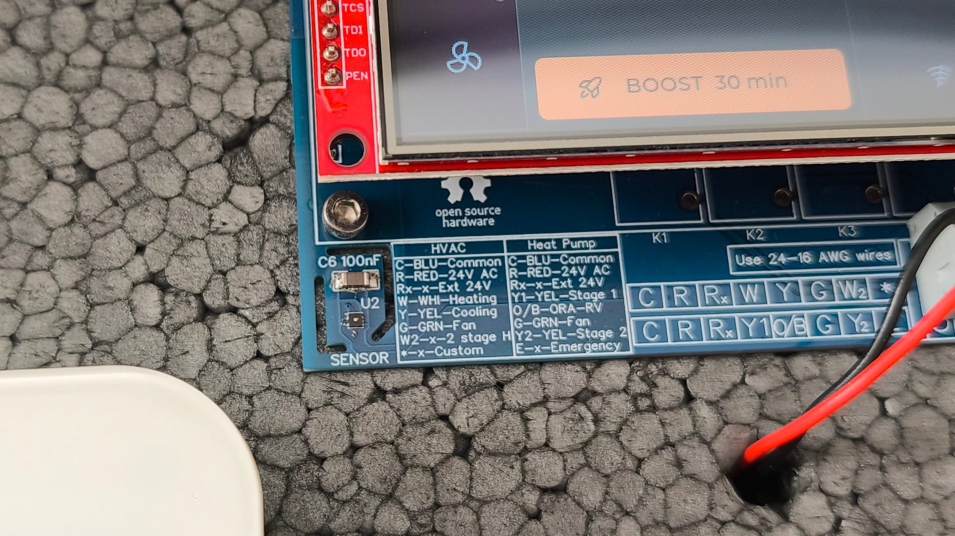
For the next revision, I removed the copper fill around the sensor and added two L-shaped slots to create an air gap around that section of the PCB. I kept two narrow bridges: one carries the sensor connections while also providing mechanical support, while the other is purely structural.
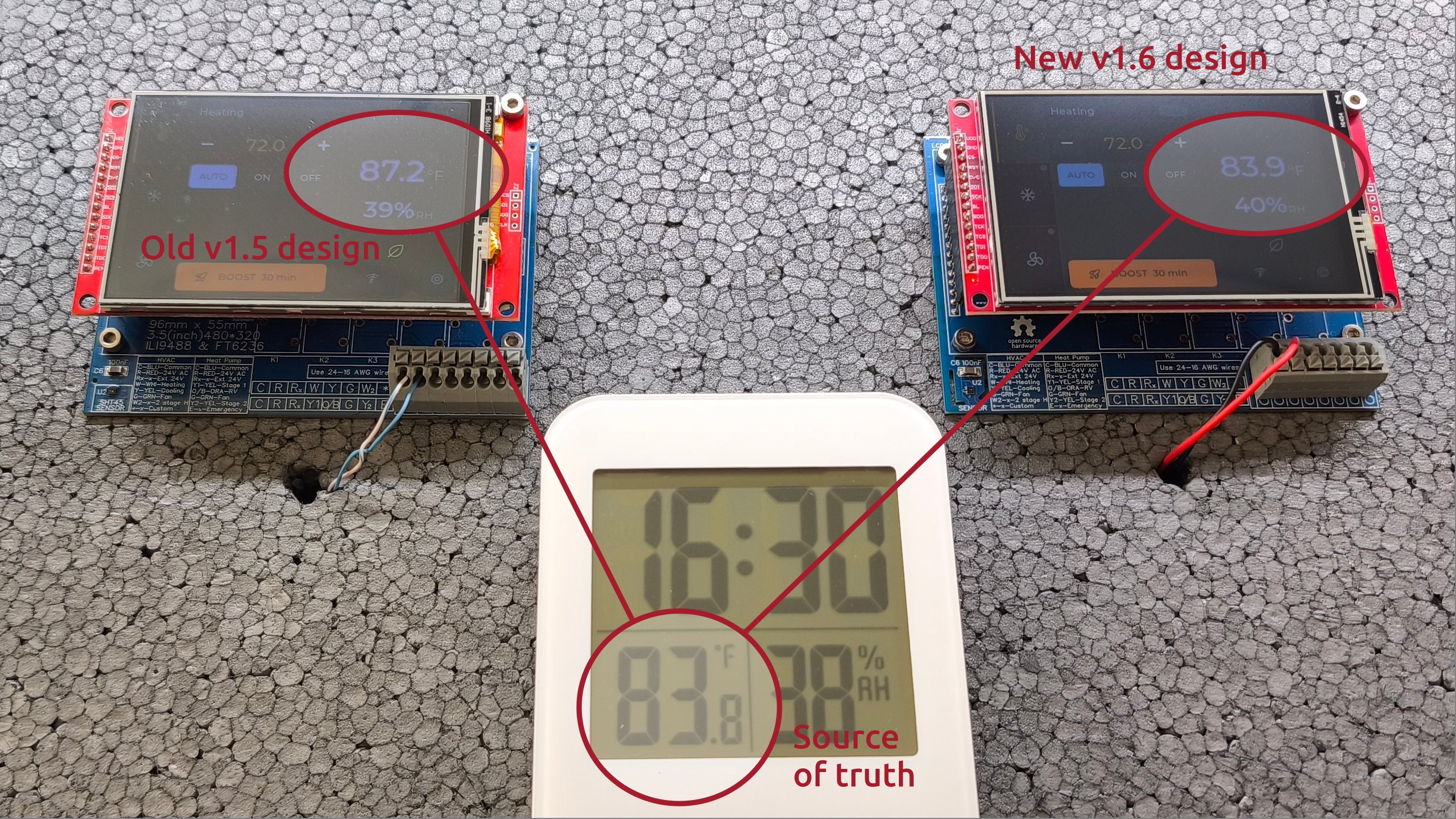
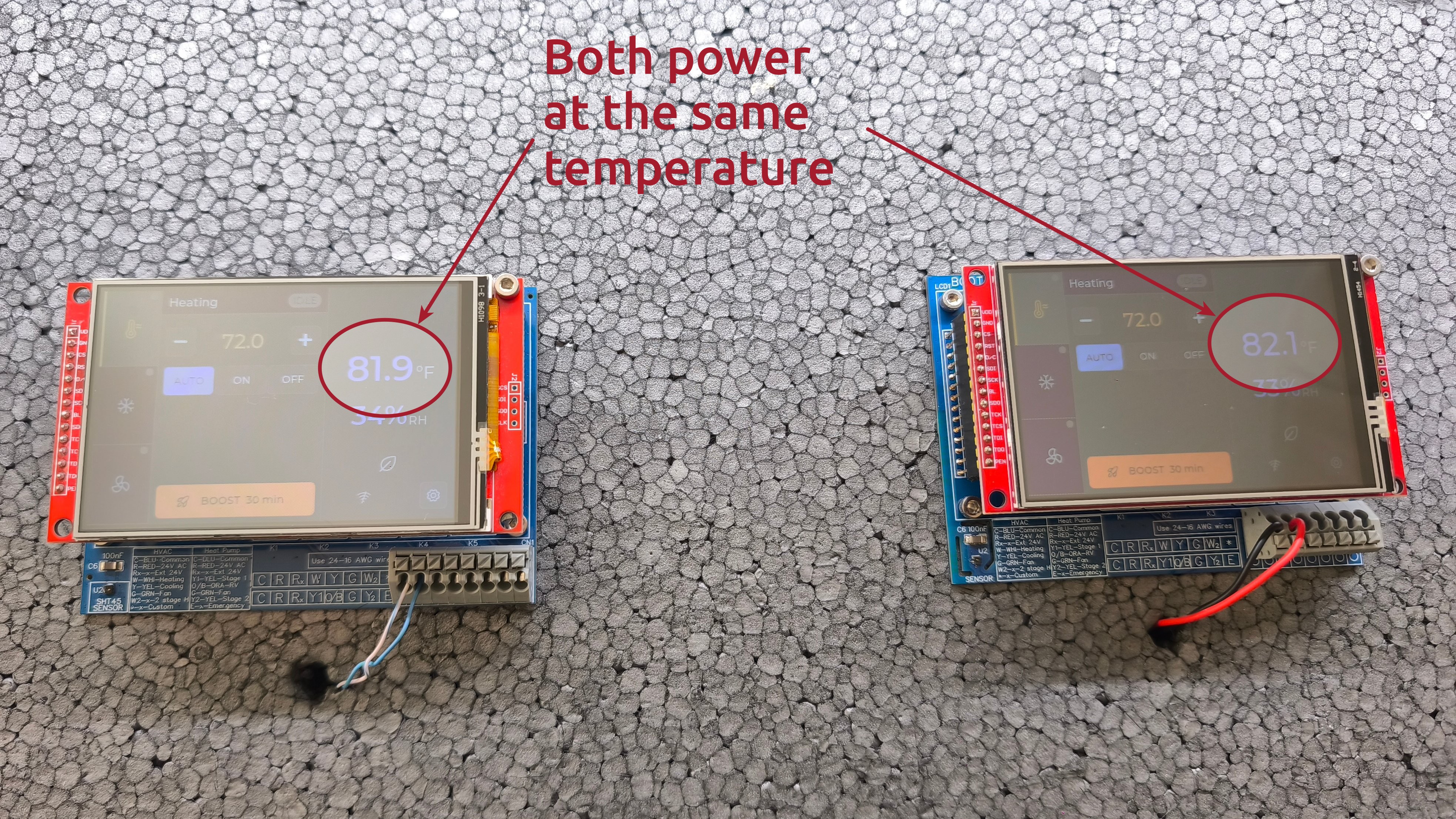
I then tested the two revisions side by side on a 10 cm thick styrofoam "wall", powered from the same 24V AC source and connected to Wi-Fi. The displays were deliberately left on continuously to maximise power consumption and therefore heat generation.
After two hours:
- Old v1.5: 87.2°F
- New v1.6: 83.9°F
- Reference thermometer: 83.8°F
That reduced the measured temperature error from +3.4°F to +0.1°F, or roughly a 97% reduction.
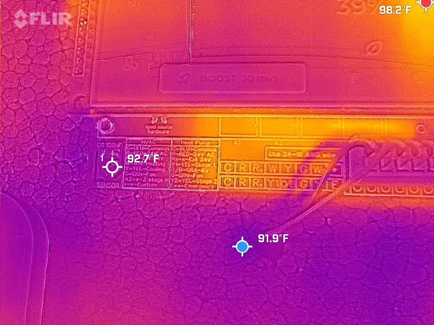
A thermal camera made the difference particularly obvious. On v1.5, the copper fill creates a visible thermal path towards the sensor. On v1.6, the copper-free area and PCB slots substantially isolate the sensor from the rest of the board.
There is still more validation to do, but the new design is behaving much closer to what I want: the sensor measures the environment rather than the PCB.
Next up: continued hardware validation and the touchscreen UI.
Discussions
Become a Hackaday.io Member
Create an account to leave a comment. Already have an account? Log In.