A Current Transformer (CT) was chosen for the simplicity of the design and ease of construction. It does, however, introduce some problems.
A CT is an ampere-turn device, and fault transients will induce a current on the secondary proportionate to the number of turns and the voltage determined by the reset impedance. D105 & D106 clamp the voltage to ~ 9V which U101 can safely handle with support from R112 & D107. This arrangement also eliminates CT polarity requirements. The zener diodes must be able to absorb the current: with a 22 turn secondary, 250A on the CT primary is ~ 12A on the secondary.
Note that a TVS is a better candidate for handling this much power, but they are many times more expensive than a pair of zeners. Be sure to evaluate that maximum fault current your system is capable of and adjust as needed.
MOVs are not viable because of the spread between their rated & clamping voltages.
A CT can also function as a transformer and impress a voltage on the secondary proportionate to the number of turns. This occurs with AC noise on the open primary, and is usually sourced from the inverter or charger (in that order). The resulting RMS value on the Sense(+) node can be substantial and will materially reduce the sensitivity of the integrator. C108 functions as a simple low-pass filter to reduce the noise profile to a level that maintains an adequate noise margin.
The above trace shows the amplitude of the noise pickup on the unconnected secondary of the CT installed on my system's grounding conductor. The peaks are clamped by the zener diodes embeded with the CT.
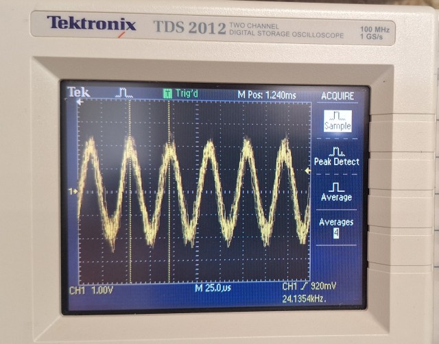
This trace shows the injected 24kHz signal with low-pass filter C108. This image was taken in the operating system with the inverter supporting a 3kW load.
C108, D105, and D106 are deliberately embedded at the current transformer to minimize the current loop & noise footprint.
Adjusting the number of turns on the CT’s secondary can be used to adjust sensitivity & current handling capability.
Reducing the number of turns reduces the initial impedance and may require a higher drive. But, it also improves the signal to noise ratio and could improve sensitivity for lower power applications. The reset current will also be higher.
Increasing the number of turns offers little advantage aside from reducing the reset current. Sensitivity will be reduced by a poor S/N ratio and a reduced impedance drop for a given fault current.
Any changes to the number of turns will require adjustments to R112, R113, and R114. If R112 is changed make sure that the current thru it doesn’t exceed ~ 15mA at the 9V reset voltage.
Electromagnetic Interference During normal operation, the unit impresses a 100mV, 24kHz, signal on the ground bus. If the ground bus is shorted (e.g., to create a conducting loop per the prescribed test procedure), a 100mA AC current will flow. The wavelength of a 24kHz signal is ~ 12,500 meters, so it is unlikely that the grounding system could function as an unintentional emitter. This said, be sure to evaluate your system for spurious operation.
Component Tolerances Since the design is based on the integration of a fixed frequency halversine signal, it’s performance is susceptible to power supply accuracy and component tolerances. For these reasons precision resistors (0.05% tolerances) & C0G/NP0 MLCCs are used throughout much of the design. Prototype testing with X7R MLCCs demonstrated that the thermal drift from operating at higher temperatures (>35~40C) increased the integrator’s ‘normal’ (no fault) output which, at the extreme could cause a false trip
 Brian Cornell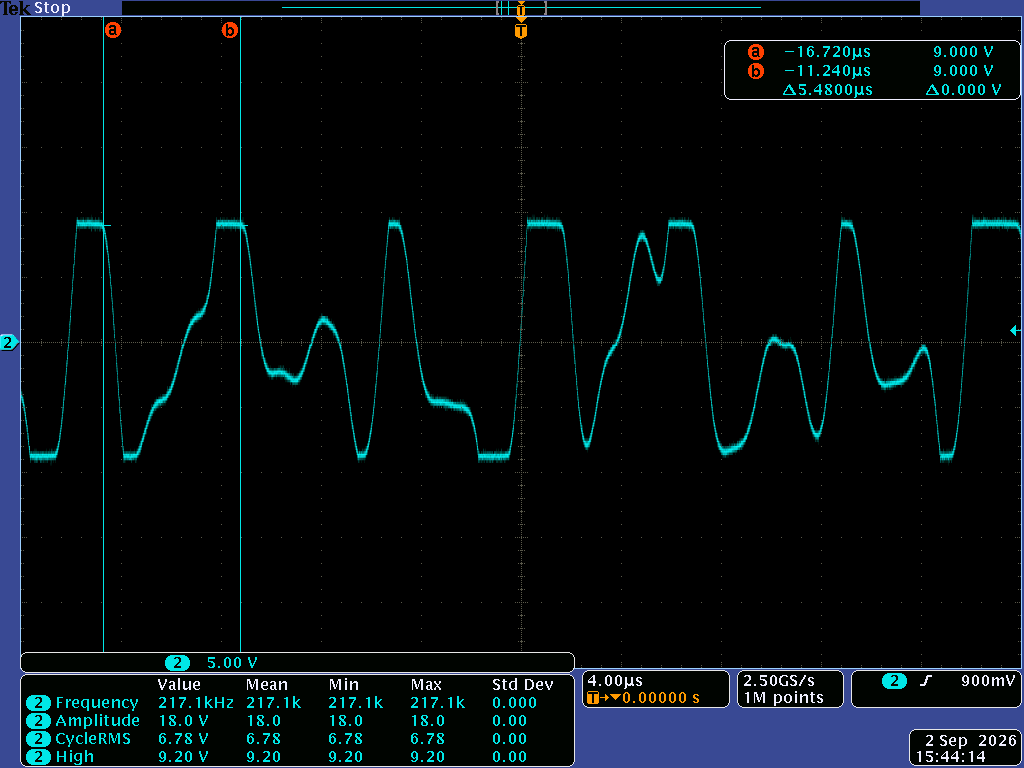
Discussions
Become a Hackaday.io Member
Create an account to leave a comment. Already have an account? Log In.