 Brian Cornell
The National Electrical Code is comprehensive, constantly evolving, sometimes difficult to understand, and often hotly debated. In my limited experience of reading it & the message boards of professionals, grounding of battery systems is one such area.
Article 690 specifically deals with residential & light industrial PV implementations but ignores batteries. I suspect this is because until recently most installations were grid-tied only. You have to go to Article 250 to divine requirements for battery-derived DC systems under 1.5kV. For my analysis, the most relevant sections are:
- 250.6 Objectionable Current (defined qualitatively; no quantitative limit),
- 200.7 Means of Identifying Grounded Conductors,
- 250.28 Main Bonding Jumper and System Bonding Jumper,
- 250.102 Grounded Conductor, Bonding Conductors, and Jumpers,
- 250.162 Direct-Current (dc) Circuits and Systems to Be Grounded,
- 250.164 Point of Connection for dc Systems,
- 250.166 Size of the dc Grounding Electrode Conductor,
- 250.167 Direct-Current (dc) Ground-Fault Detection,
- 250.168 Direct-Current (dc) System Bonding Jumper.
250.162 specifies that DC systems between 60 & 300 volts must be grounded, and 250.164 & 250.166 go on to specify the location & size of the grounding conductor. This implies that 48V battery systems are excluded. However, these systems are typically operating at 53~56 volts with the ability to instantaneously source >1kA, and the safety risks of allowing them to float merit strong consideration for grounding (these voltages can be lethal).
250.167 indicates that ground fault detection is permitted for DC grounded systems, and Article 1 defines Ground-Fault Detector-Interrupter, dc (GFDI) as “A device that provides protection for PV system dc circuits by detecting a ground fault and could interrupt the fault path in the dc circuit”.
The methods prescribed in the details above rely on the equipment circuit breakers (CB) to open in the event of a ground fault short, and since these CBs are sized for system capacity - typically 100's of amps - the grounding conductors must be sized to that of the ungrounded conductors - typically 2/0 AWG or larger depending on the system's capacity (a 2/0 wire is 0.364" without insulation). This further implies that the Equipment Grounding Conductors (EGCs) on all associated equipment - inverters, chargers, etc. - should be sized accordingly since it's expected that the grounding system be capable of supporting the full system load.
That's a lot of copper that will easily double the size of required conduit and mandate a grounding bus bar outside of the usual AC CB enclosure grounding block (termination lugs use 3/8" bolts). This adds bulk & cost (3/0 AWG welding or MTW is ~ $6/foot right now), and most importantly does not address what I believe is the most likely fault scenario: a moderate impedance short.
I define this as a short that conducts enough current to go unnoticed for some time (e.g., no immediate equipment failure, no CB trip), but risks fire thru arcing & heat generation.
Alternative Methods
Many BMS & chargers implement a rapid shutdown circuit that operates when a low voltage circuit is opened (the term “Rapid Shutdown” as used here addresses one aspect of the shutdown requirements specified in NEC Article 690.12, “Rapid Shutdown of PV Systems on Buildings”). These methods may permit the safe use of a 6 AWG stranded conductor to be used as the grounding conductor along with conventional bus bar grounding methods.
This is the gauge typically used for equipment grounding conductors. From the Wikipedia wire gauge chart the 10s fusing current is 668A per Preece’s measurements, and Onderdonk’s 1s fusing current is 4kA. You will need to evaluate if a sufficient safety margin exists based on the total time to stop current flow in your equipment and what its maximum current sourcing capabilities are.
A safe rapid shutdown requires disconnecting the DC energy sources, typically the battery & charger, so the opening of two low-voltage circuits is required. This can be accomplished using a ganged DC circuit breaker or by electronic means.
Ganged DC circuit breaker
This method implements a DC circuit breaker rated for a few amps and ganged to an auxiliary contact unit (the breaker must havean interrupt rating of 10kA or higher). The breaker is placed between the grounding pole of the battery bus bar and the grounding conductor.
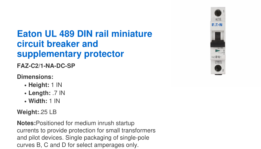
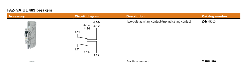
An example from Eaton is their UL 489 DIN rail solution for a cost of ~ $170.
Electronic Detection
This method uses a magnetic sensor to detect current flow in the grounding conductor to open a relay connected to the battery & charger rapid shutdown circuits (e.g., the BGFD). The grounding conductor is routed thru the magnetic sensor, a toroid. Total cost for the unit, including PCB, enclosure, and sensor assembly: $82.
Discussions
Become a Hackaday.io Member
Create an account to leave a comment. Already have an account? Log In.