 Arnov Sharma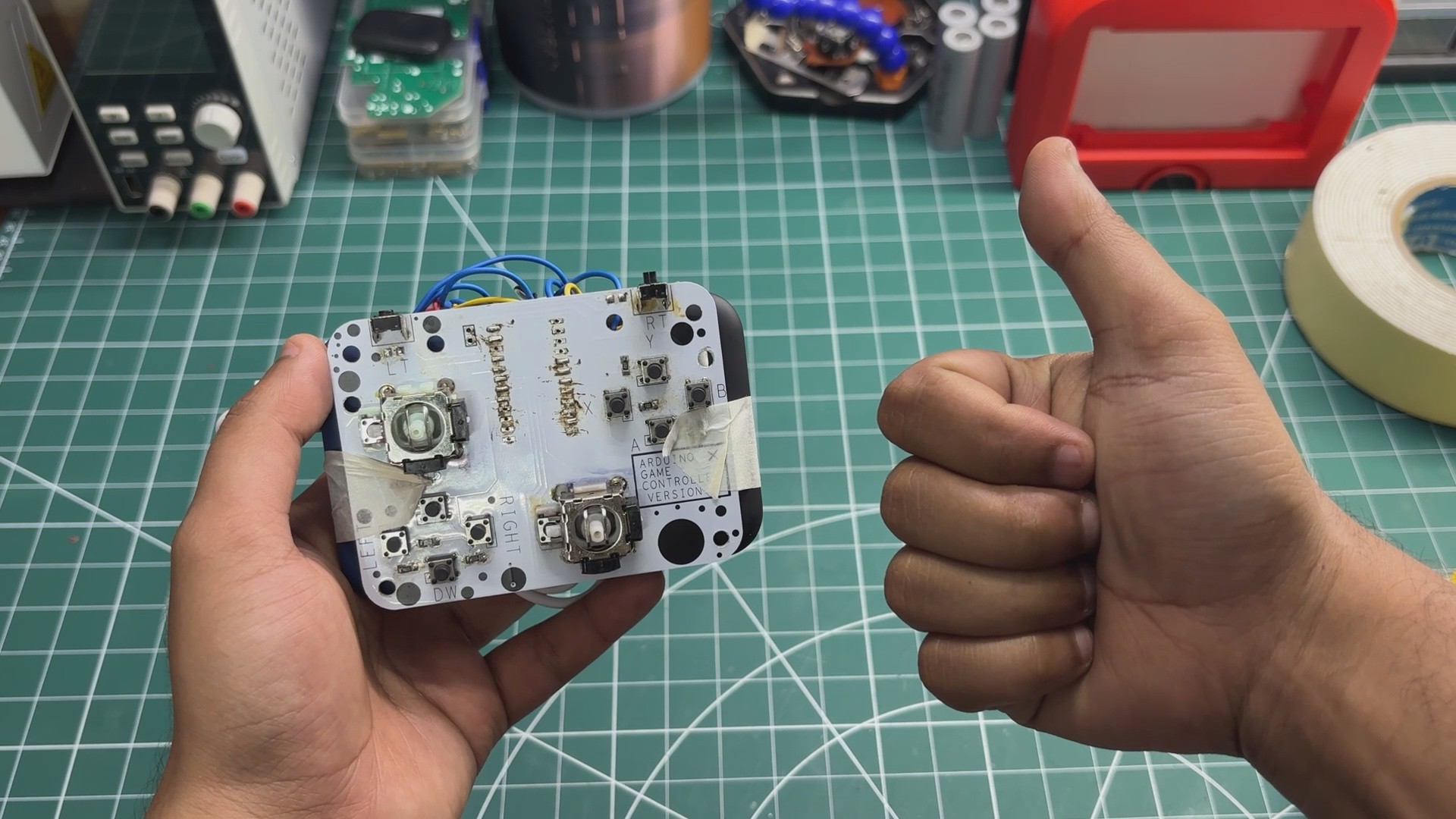
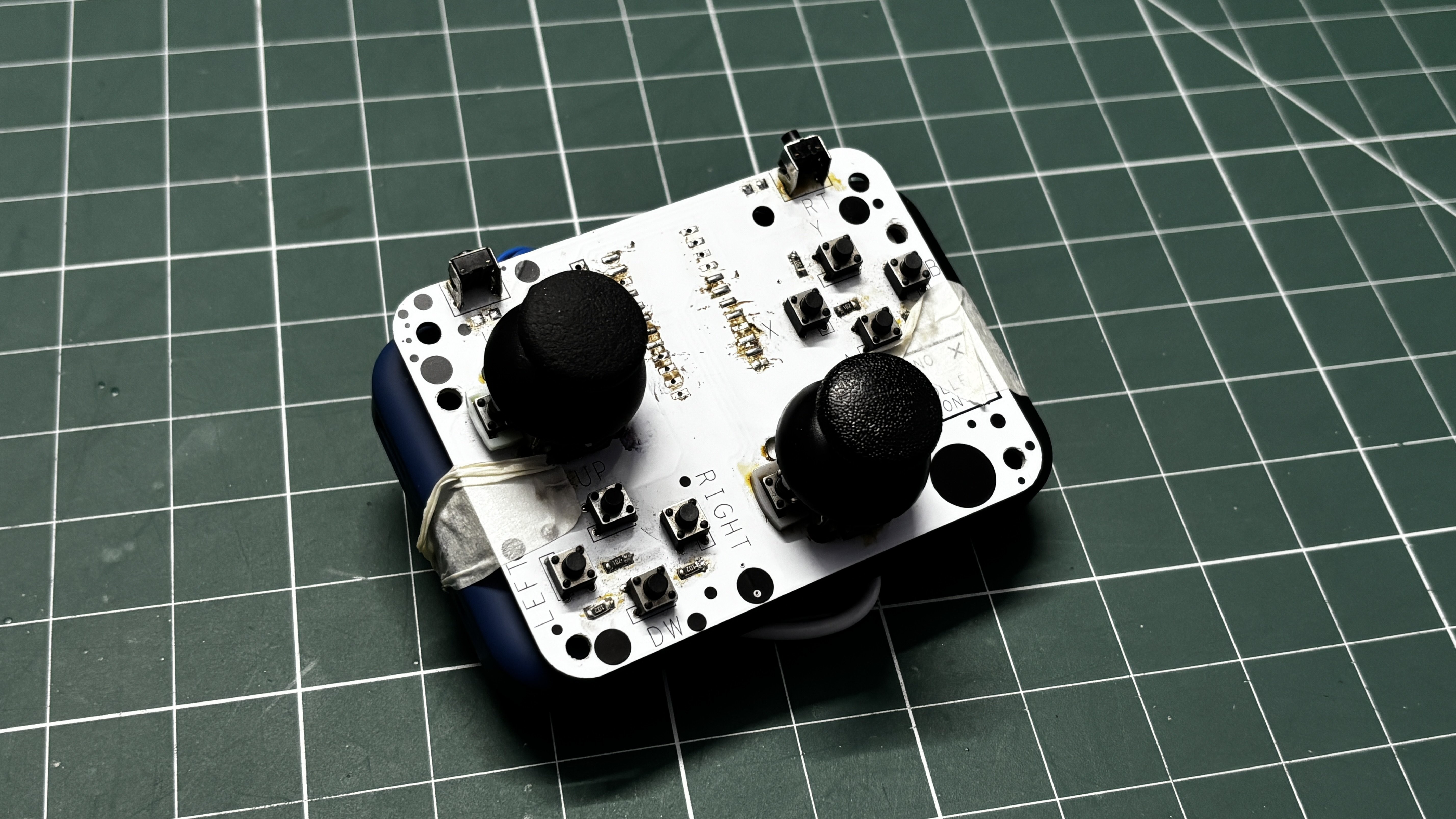
For the prototype, I reused the PCB from a wired game controller I built previously. That board was originally designed around an Arduino Pro Micro and the ATmega32U4. By replacing the Pro Micro with an Arduino Nano ESP32, I can take advantage of the ESP32-S3's built-in Bluetooth Low Energy and turn the same basic controller hardware into a wireless gamepad.
The prototype is already fully functional and can connect to a computer over Bluetooth and work as a regular game controller. I’ve been using it to play games like Cyberpunk 2077 and NieR while testing the hardware and firmware.
This isn't the final controller yet. The eventual version will have a completely custom PCB, a purpose-built enclosure, and a much more refined design. For now, this prototype is about proving that the concept works and laying the groundwork for the open-source controller project.
This article covers the complete build process of this prototype, so let's get started with the build.
MATERIALS REQUIRED
These were the components used in this build
- Custom PCB (Salvaged from previous Project)
- Arduino Nano ESP32 Board
- Right-Angle Push Buttons
- Horizontal Push Buttons
- Analog Joysticks
- Power bank
- USB to Type C Cable
- Double-sided tape
HARDWARE—ARDUINO GAME CONTROLLER
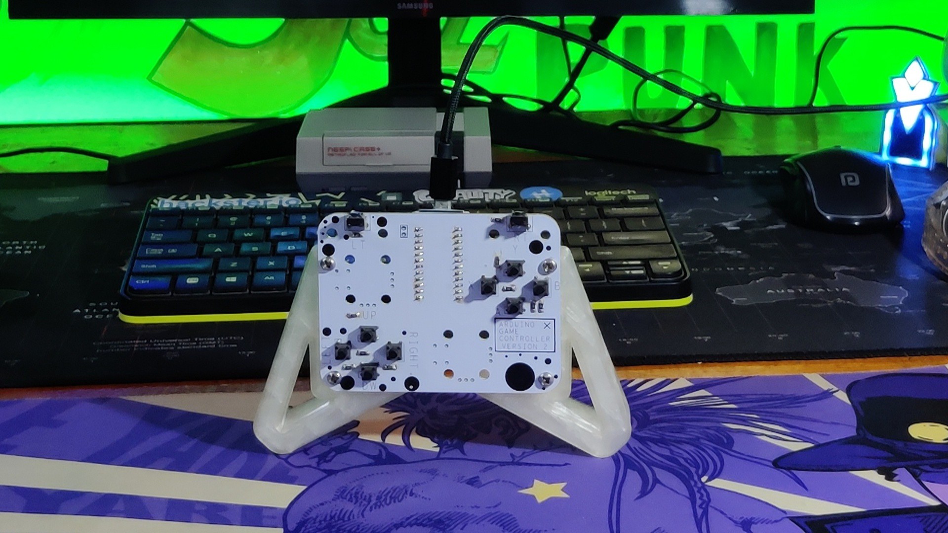
If the Arduino Nano ESP32 is the brain of this project, then the previously made game controller PCB is definitely the brawn.
For this project, I'm reusing the main joystick and button PCB from my previous Arduino game controller project. In the original version, an Arduino Pro Micro was connected to this PCB and acted as the interface between the controller and the PC. Using the ATmega32U4's native USB HID support, I was able to control games and use the board as a regular game controller.
The most interesting part of this controller, however, is that only one I/O pin is used to control all 10 buttons on the board. I achieved this using a clever resistor voltage-divider setup, which allows the microcontroller to identify which button is being pressed by reading different voltage levels from a single analog pin. I'll explain how this works in the next step.
I had also designed this PCB with provisions for two thumbsticks, which is something I was able to take advantage of for this wireless version.
For a more detailed look at the construction and the other design decisions behind the original controller, check out its project page.
https://www.hackster.io/Arnov_Sharma_makes/arduino-retro-game-controller-7cdd0e
PCB DESIGN
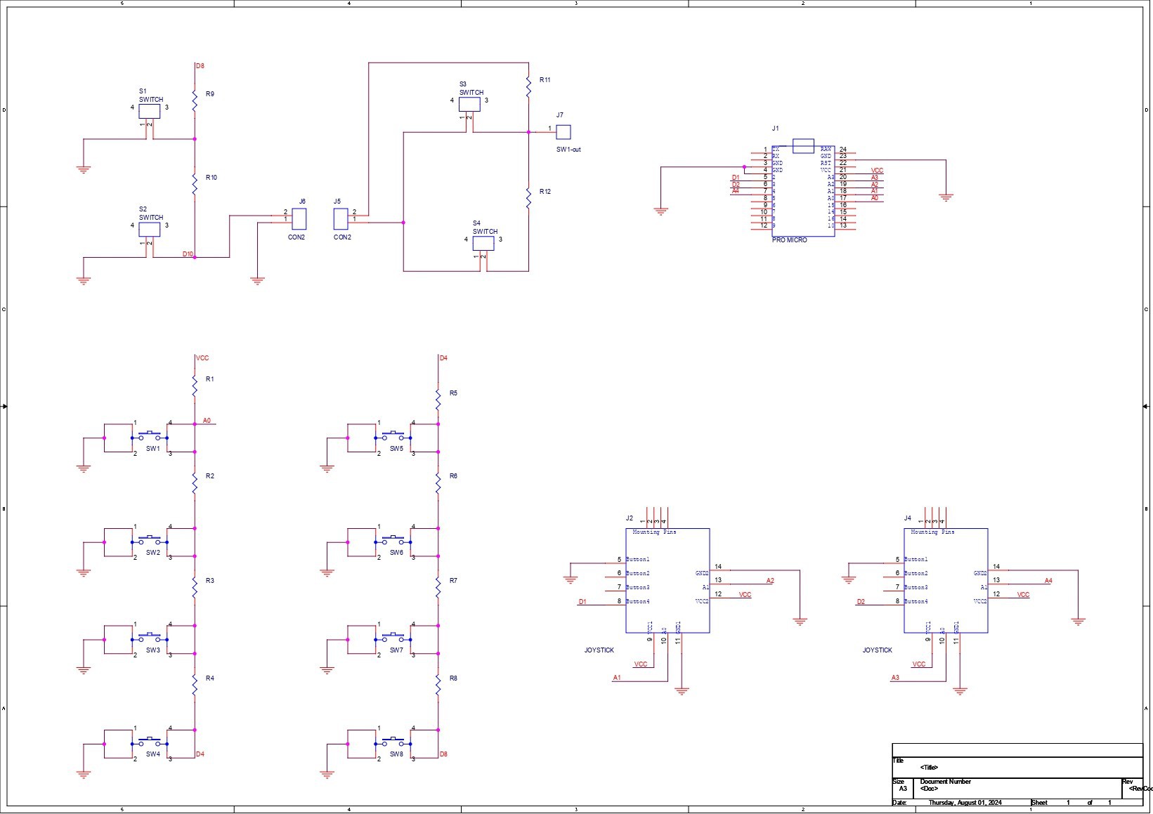
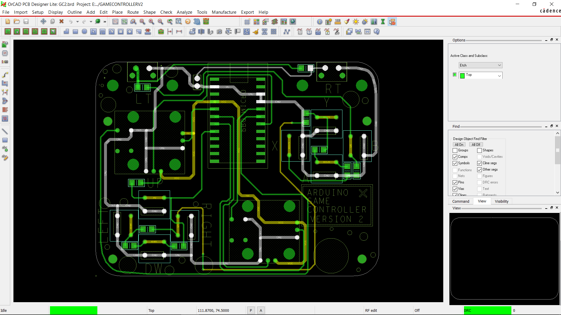
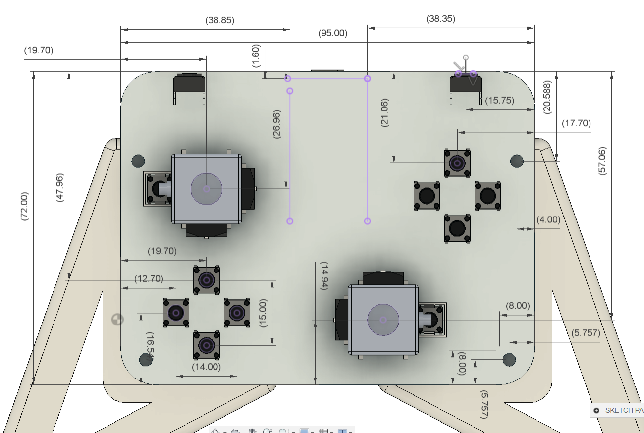
For this project, I made a fairly traditional, straightforward game controller PCB, with the buttons connected to the GPIO pins of a microcontroller that supports HID, since the original version was designed as a wired game controller.
The interesting part is how I managed to connect 10 buttons using a single I/O pin.
For this, I built a resistor-ladder arrangement using twelve 1 kΩ resistors connected in series between VCC and the button inputs. Each button connects to a different point on the resistor ladder, while the other side of each switch is connected to ground.
When a button is pressed, it produces a different voltage at the shared analog input depending on its position in the resistor ladder. The microcontroller reads this voltage through its ADC and can determine which button was pressed based on the measured value.
This approach makes it possible to connect a large number of buttons to a single analog I/O pin, instead of needing a separate GPIO pin for every button. In practice, you can use this technique to fit 10–20 buttons or even more onto a single input, depending on the resistor values, ADC resolution, and how much tolerance you can accommodate.
PCBWAY SERVICE
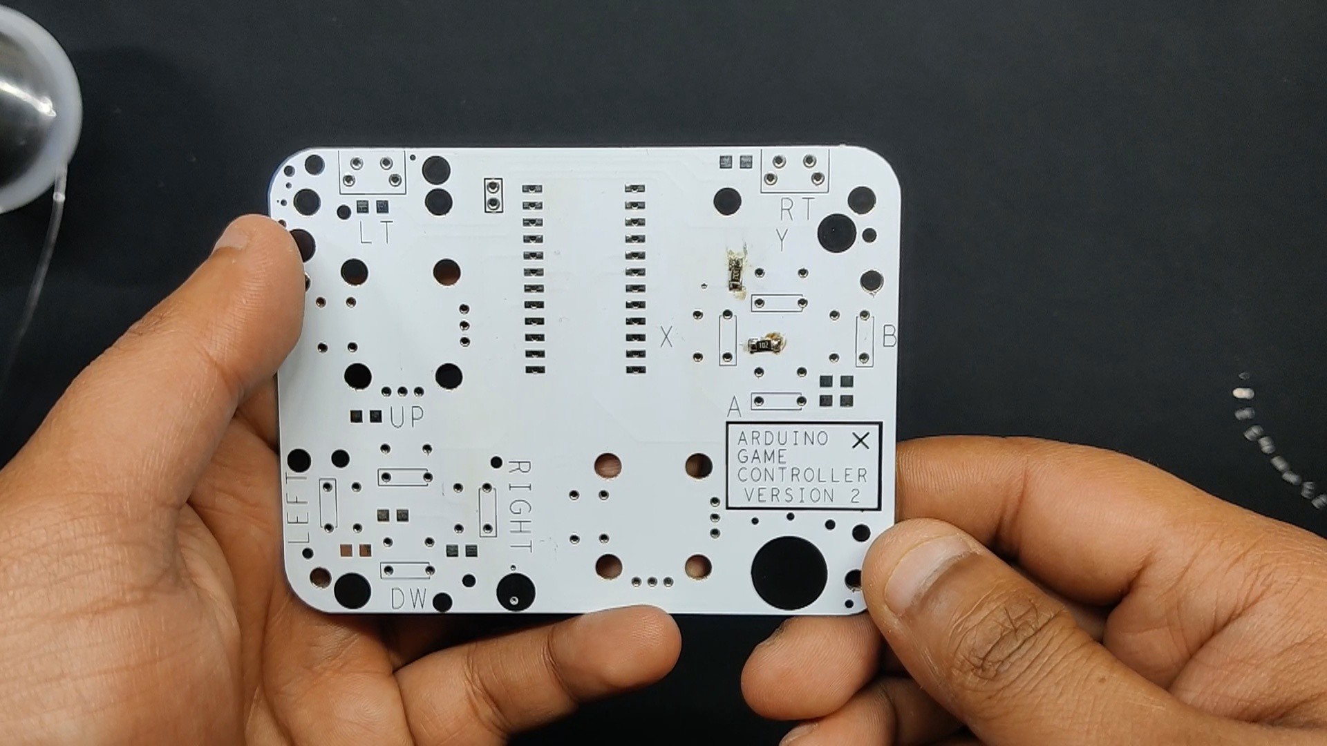
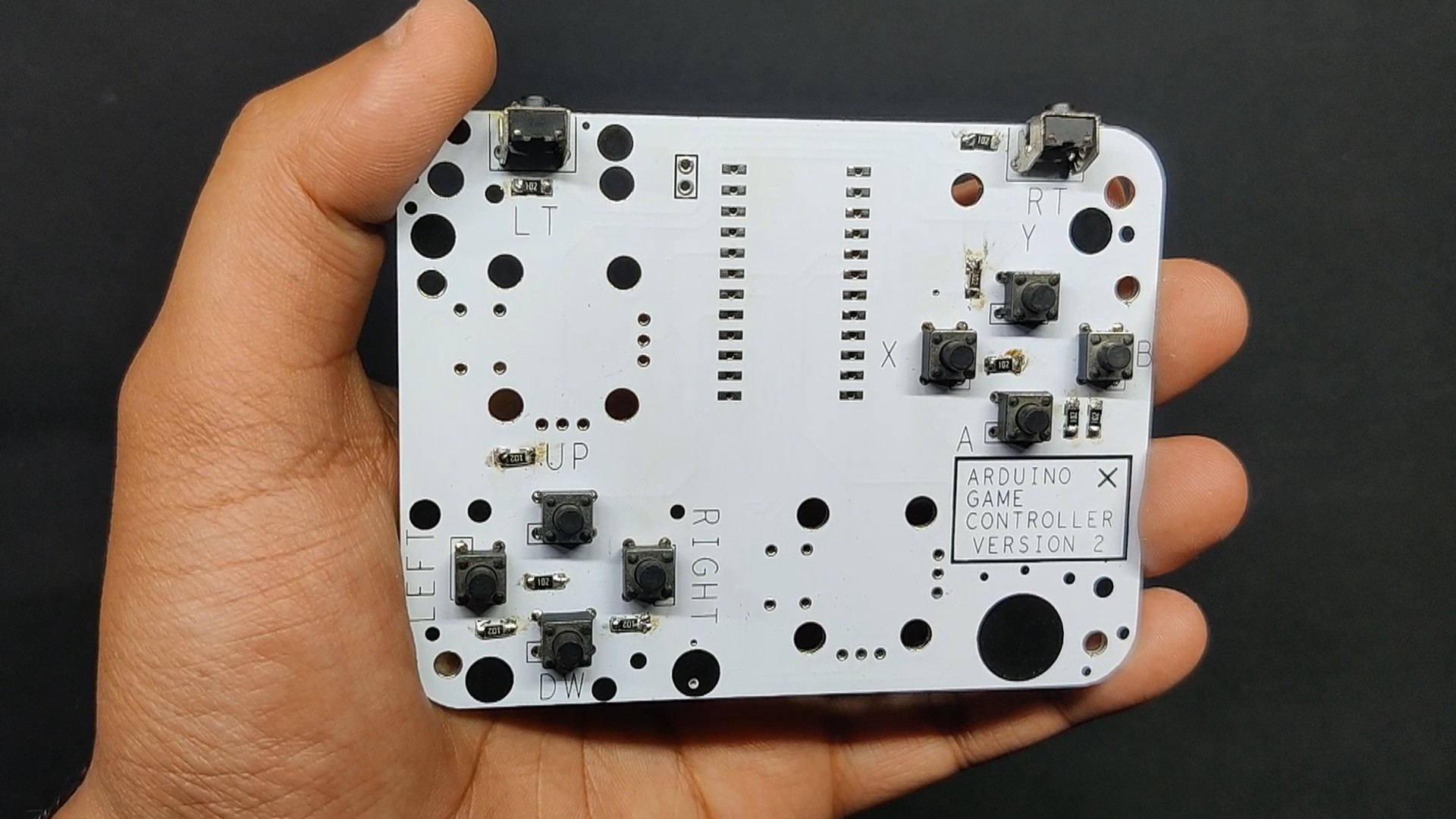
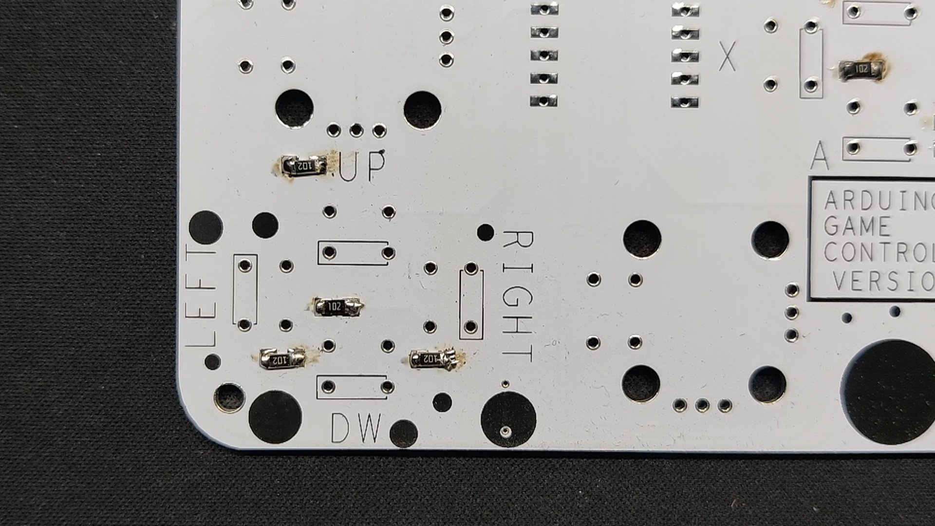
After finalizing the design, I generated the PCB Gerber file and sent them to PCBWay for fabrication. I chose a White PCB with a Black solder mask.
The quality turned out to be excellent with a clean finish and sharp silkscreen, and everything matched the design perfectly.
Over the past ten years, PCBWay has built a strong reputation for providing reliable PCB manufacturing and assembly services, becoming a go-to choice for engineers and makers worldwide.
Honestly, if you’re making custom PCBs and not checking out PCBWay, you’re just making things harder for yourself. They also offer CNC machining and 3D printing services.
HOW THE VOLTAGE DIVIDER-BUTTON SETUP WORKS
To get values of each button, we used the Analog Serial Read Sketch from the example menu and used it to get values of each button.
void setup() {
Serial.begin(9600);
}
void loop() {
int sensorValue = analogRead(A0);
Serial.println(sensorValue);
delay(1);  // delay in between reads for stability
}
The A0 analog pin is used to read the different voltage values generated by the resistor ladder when a button is pressed.
For example, pressing the UP button produces an analog reading of around 0, while pressing DOWN produces a reading of around 511. Every button produces its own distinct value.
In the code, I define the expected value for each button along with a small tolerance range. The controller continuously reads the analog value from A0 and compares it against these predefined values. If the reading falls within the expected range for a particular button, that button is considered pressed; otherwise, it is treated as released.
This is what allows the controller to identify multiple buttons through a single analog input.
And even after replacing the Pro Micro with the Arduino Nano ESP32, this part of the original controller remains exactly the same. The resistor ladder and A0 input continue to handle all of the button inputs; only the microcontroller handling those readings has changed.
HARDWARE- ARDUINO NANO ESP32
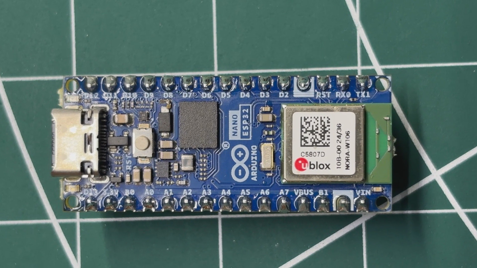
The brain of this project is the Arduino Nano ESP32, which serves as the main microcontroller for the game controller.
For this prototype, I essentially replaced the Arduino Pro Micro clone used in my previous wired controller with the Arduino Nano ESP32. While the Pro Micro is based on the ATmega32U4, the Nano ESP32 is built around the ESP32-S3, giving the controller a significant increase in processing power, memory, and connectivity.
The Arduino Pro Micro uses an 8-bit ATmega32U4 AVR microcontroller running at 16 MHz. It has 32 KB of flash memory, 2.5 KB of SRAM, and 1 KB of EEPROM. Its major advantage for the original controller was native USB support, allowing it to communicate with a computer as a USB HID device.
The Nano ESP32 uses the ESP32-S3, a 32-bit dual-core microcontroller based on the Xtensa LX7 architecture, with a clock speed of up to 240 MHz. The ESP32-S3 includes 512 KB of SRAM, 384 KB of ROM, and additional RTC memory. The Nano ESP32 board also provides external flash memory for program storage.
The biggest advantage for this project, however, is connectivity. The ESP32-S3 includes an integrated 2.4 GHz Wi-Fi radio and Bluetooth Low Energy (BLE), eliminating the need for an external Bluetooth module.