 Srinivasan M S
Project Overview & Objectives
This project is a low-cost, workshop-built cricket bowling machine designed primarily for children practicing with lightweight 65 mm plastic cricket balls.
Built using readily available materials, the working prototype provides consistent ball delivery and incorporates a custom mechanical sequencing system for reliable single-ball feeding.
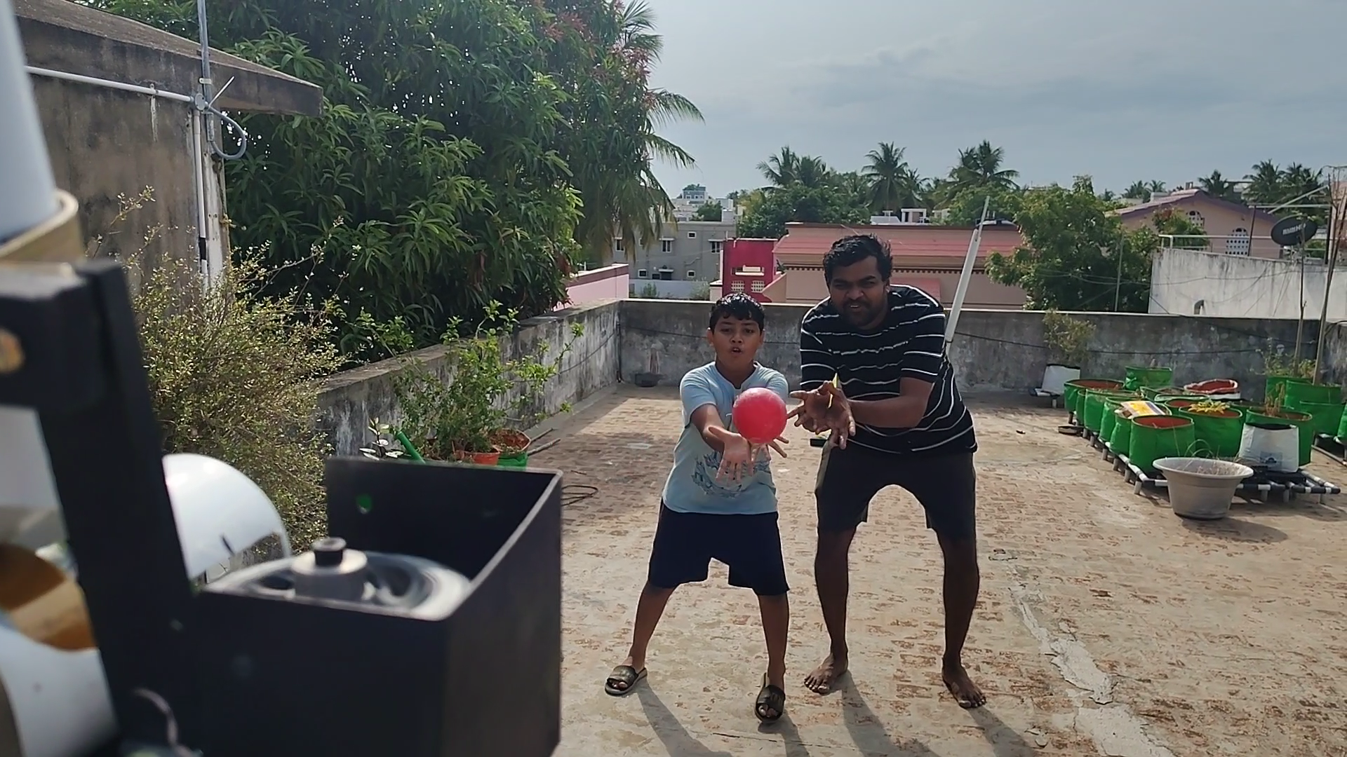
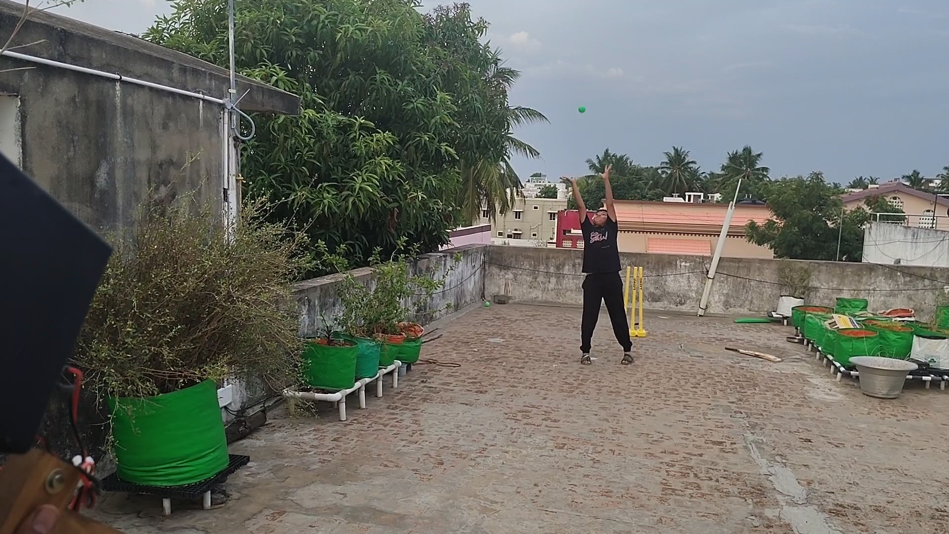
Beyond standard batting practice, real-world field testing revealed two additional training modes: slip-catching practice and high-catching practice, achieved by tilting the frame upward.
The machine is now considered a completed prototype and will remain unaltered for a 6-to-12-month period to observe its long-term reliability.
Core Requirements
- Target ball: 65 mm lightweight plastic cricket balls.
- Consistency: Reliable, automated single-ball delivery.
- Anti-jamming: Prevent uncontrolled multiple-ball feeding into the propulsion zone.
- DIY architecture: Maintain a simple mechanical layout using commonly available materials and workshop tools.
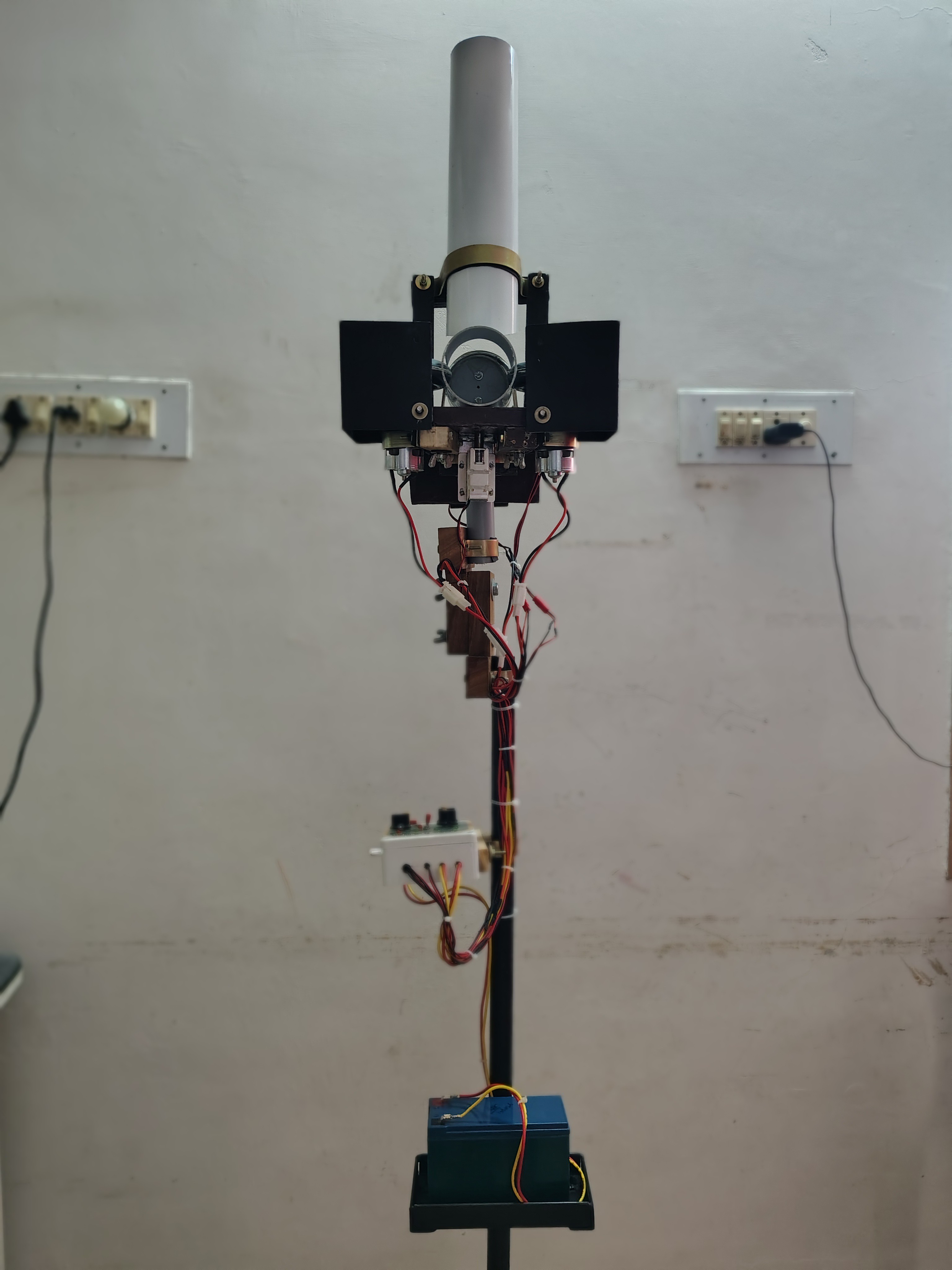
Technical Architecture & Working Principle
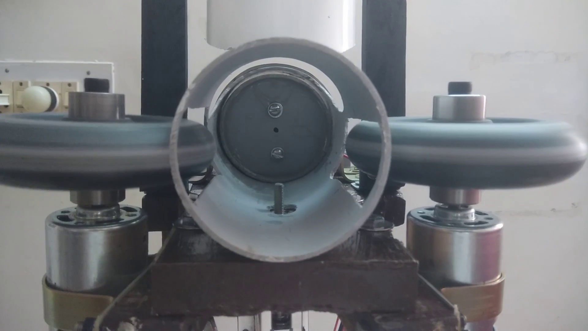
The propulsion mechanism uses two high-speed wheels spinning in opposite directions. Driven independently by dedicated RS775 DC motors, the friction generated compresses the ball through a set gap, accelerating it forward. Adjusting individual motor voltages via a 555-timer PWM setup controls ball speed and delivery dynamics.
Component Checklist:
- Propulsion System: 2× RS775 DC Motors, 2× 4" Polyurethane (PU) wheels, custom machined MS hubs, motor clamps, wooden mounting blocks, and rubber isolation pads.
- Feeding Mechanism: 2½" PVC pipe (chute/barrel), custom 1¾" PVC piston, crank disc, linkage arm, and a 30 RPM geared DC motor.
- Sequencing & Power: 12V Solenoid with a blocking pin, boundary micros witches for home-position tracking, 555 PWM controllers, and a 12V 7.2Ah Lead-Acid battery.
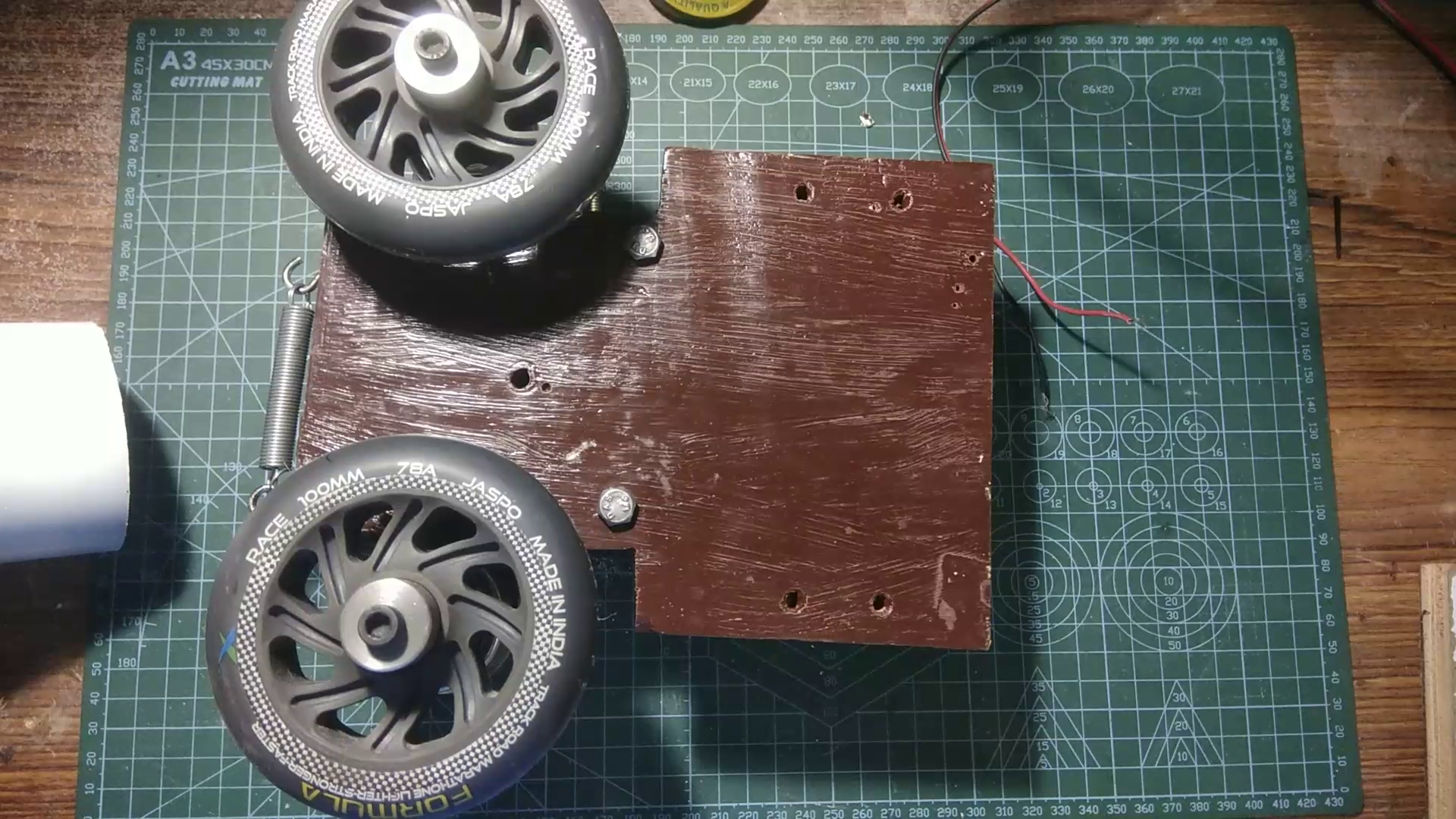
- Chassis: Hardwood base plank, heavy-duty metal brackets, adjustment tension springs, and assembly hardware.
Mechanical Evolution & Lessons Learned
1. The Dynamic Wheel Gap Failure (Slow-Motion Video Insight)
- Initial Approach: Tested single and dual spring-loaded pivot arms designed to automatically expand when a ball passed through the wheel nip.
- The Issue: High-speed video analysis revealed that under load, the assemblies didn't just open; they structurally tilted. This unconstrained twisting skewed wheel alignment, ruined energy transfer, and produced inconsistent ball delivery.
- The Fix: Pivoting arms require robust ball bearings to isolate lateral forces. For this DIY build, the complex spring arms were eliminated in favor of a rigid, manually adjusted slotted base that locks tightly into position once the ideal gap is set.
2. Solving High-RPM Wheel Vibration
Severe system noise and structural oscillation threatened early testing. This engineering bottleneck was solved through a systematic overhaul:
- Material Upgrade: Replaced generic plastic/rubber-tread wheels (which suffered from run-out, delamination, and face wobble) with 4-inch Polyurethane (PU) wheels mounted tightly via machined aluminum couplings.
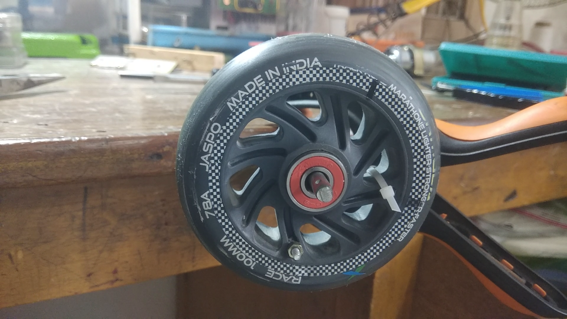
- DIY Static Balancing Setup: Lacking commercial dynamic balancers, each wheel was set on a free-spinning 6mm shaft supported by low-friction bearings. Gravitational low points identified the heavy zones. The first wheel was permanently counter weighted with a 2.19g bolt/nut combo, and the second with a 1.17g trimmed weight until both stood completely neutral at any clock position.
- Acoustic & Vibration Isolation: Layered sheets of high-density rubber and FR4 load-distribution plates were clamped between the motor bodies and the wooden framing. This limited resonance transmission, rendering the machine nearly vibration-free below 70% speed.

Automatic Single-Ball Feeding Sequence
The mechanical control stack relies on gravity and mechanical timing rather than a microprocessor.
Vertical Gravity Chute
↓
Horizontal PVC Barrel
← 1¾" Wide Piston
Blocks Upper Chute
↓
Solenoid Retracts Pin
→
Ball Pushed into Propulsion Wheels
The Integrated Piston & Gate
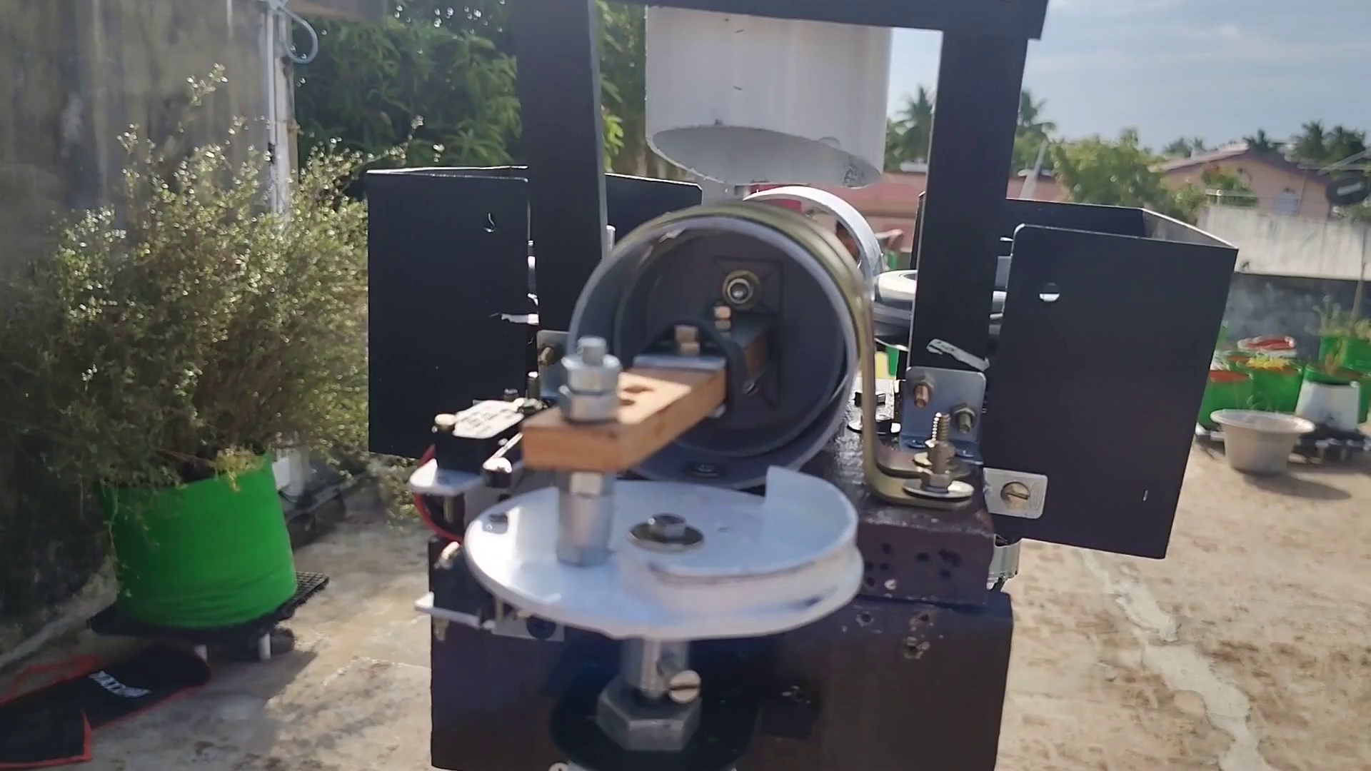
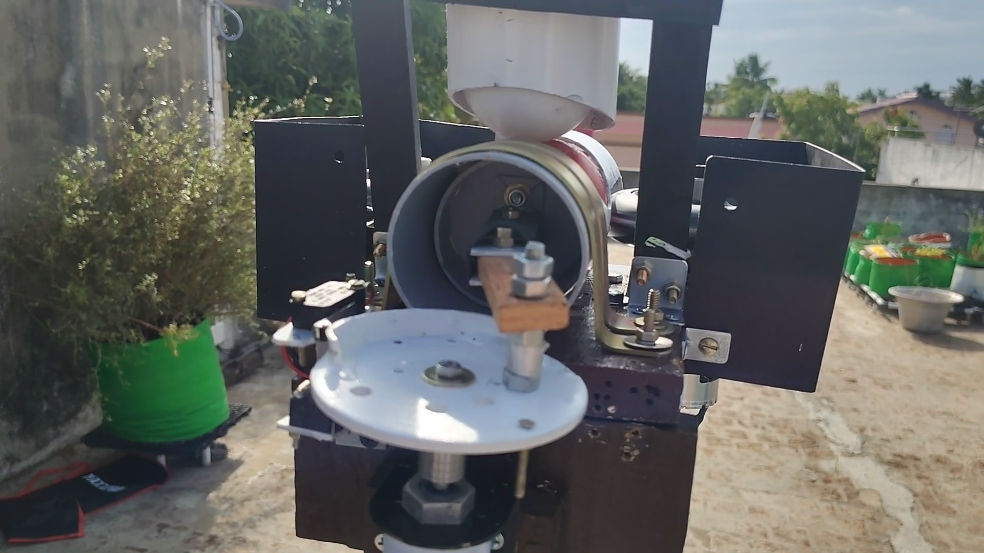
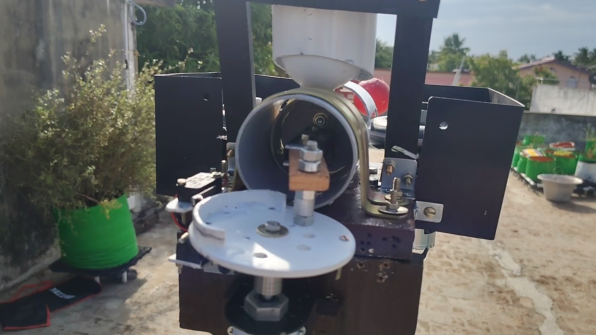
The sliding PVC piston is sized with a 1–2mm internal clearance to guarantee low friction. Its 1¾-inch structural width allows it to act as its own mechanical gate valve. When pushed forward, the piston body physically blocks the bottom of the vertical gravity chute, holding back subsequent balls until the current ball is launched and the piston retracts fully to its home position.
The 6-Phase Delivery Loop:
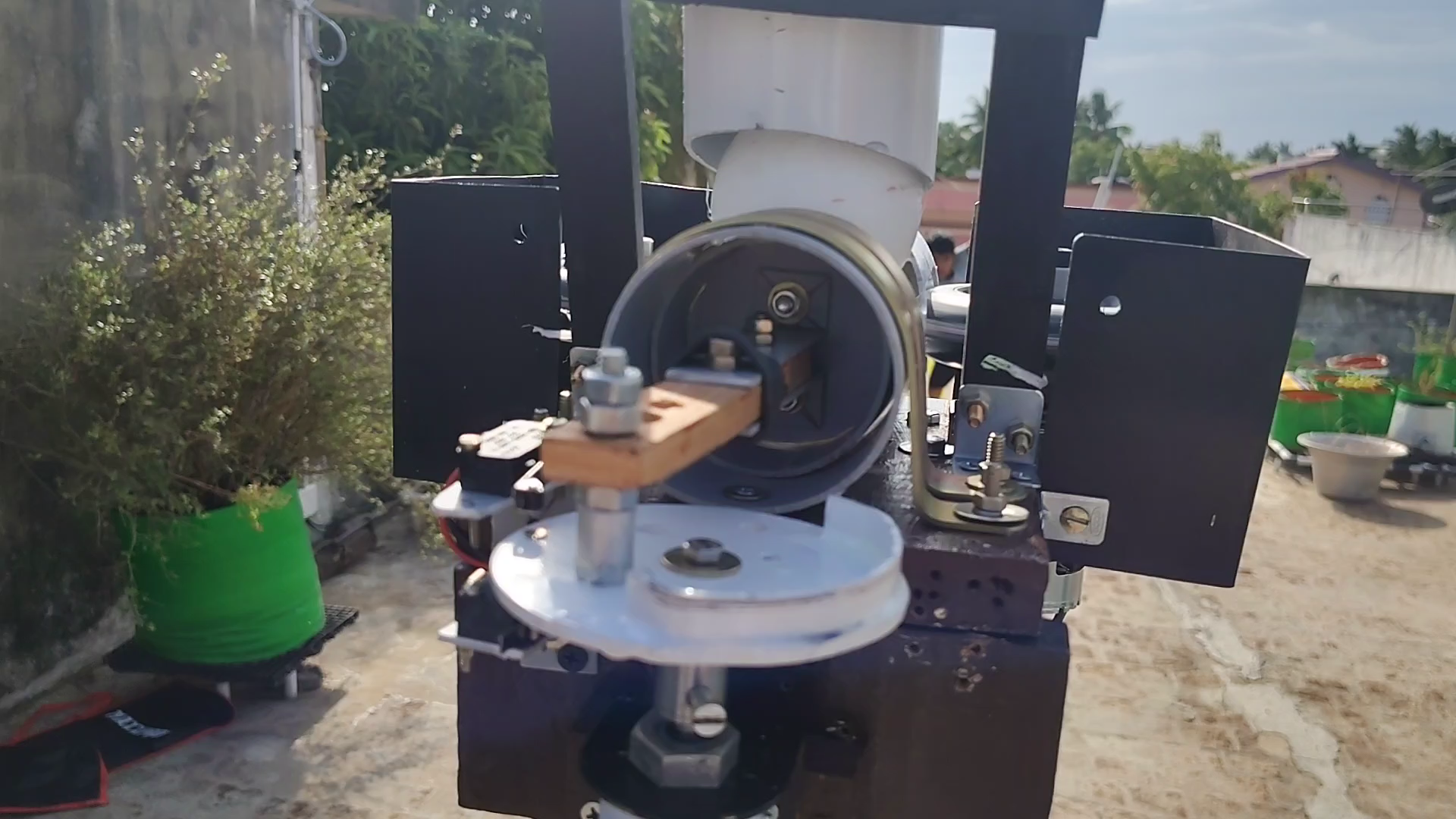
- Home Position: Piston is fully retracted, leaving the chute clear. One ball drops into the barrel; the deenergized solenoid pin physically blocks it from rolling forward.
- Cycle Trigger: The 30 RPM geared motor turns, rotating the crank disc.
- Gate Release: The 12V solenoid energizes, instantly retracting the blocking pin.
- Feed Stroke: The connecting link translates rotary motion to linear piston travel, driving the ball into the delivery channel while blocking the next ball in the chute.
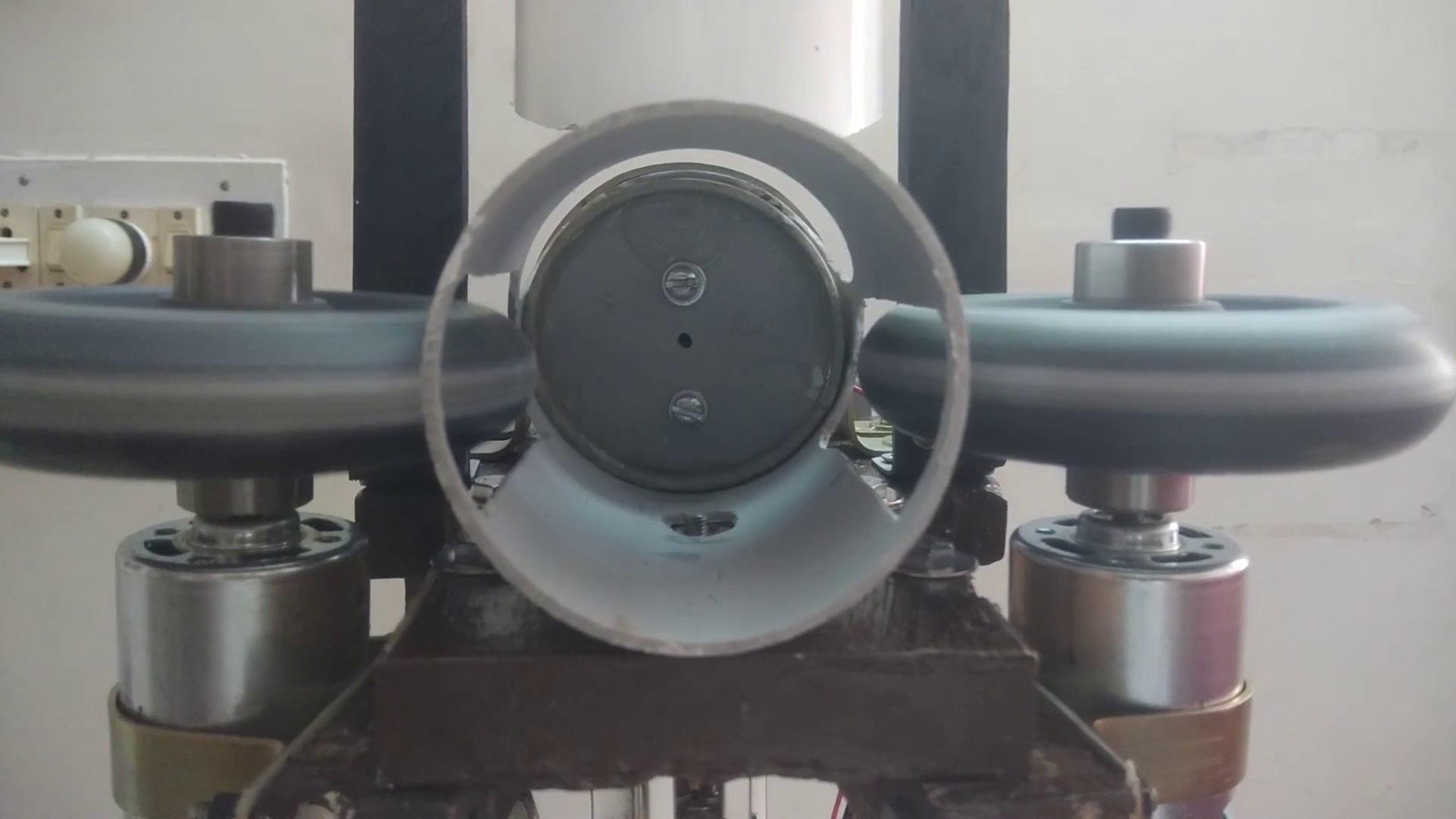
- Launch Zone: The ball passes the PVC guide, hits the high-speed wheel nip, and fires downrange.
- Cycle Reset: The crank pulls the piston back, the solenoid drops the and the blocking pin comes up, the next ball reloads, and a home-position micro switch halts the motor until the next start pulse.
Performance Observations & Field Trials
Continuous testing across single-session runs of 48 balls (8 overs) and 60 balls (10 overs) yielded crucial data points:
- Chassis Dynamics: Trajectories were linear and repeatable. The 12V 7.2Ah battery sustained high currents without voltage sag, and motor thermal rise remained minimal.
- Aerodynamic Pathing: White contact marks1 on the PU wheels confirmed that balls consistently enter slightly above center because they roll along the bottom of the feed pipe before getting gripped. Vertical adjustment of the wheels did not alter this behavior, but flight accuracy remained unaffected.
- Material Matrix Impact: Ball hardness drastically alters muzzle velocity. New, rigid plastic balls achieved excellent speeds. Worn, soft balls deformed under pressure, slipped in the nip, and absorbed energy, lowering performance.
- Tennis Ball Variations: Configured with a wider 50mm gap, tennis balls successfully fed through the system but launched with low velocity, potentially due to motor torque drop or insufficient compression.
Speed Tracking Analysis Limits
Attempts to log exact ball exit velocity using a standard smartphone camera (including high frame-rate and slow-motion video) proved inconclusive. Over short 1-meter tracking baselines, the ball moved too fast for the frame rate. Over a 5-meter window, travel clocked at 12–14 frames at 30 FPS. However, because lightweight plastic balls loses significant velocity during flight and frame-boundary timing is highly uncertain, this calculated average does not capture true muzzle speed. Precise speed quantification requires a dedicated optical gate or radar array.
Long-Term Plan & Next-Gen Concepts (ESP32)
The present system is frozen as a completed prototype for a 6-to-12-month evaluation phase to verify part durability, battery limits, and mechanical fatigue.
Future iterations will explore a separate, advanced machine using these experimental insights:
- Enlarged Wheel Diameters: Shifting to larger wheels to secure identical linear ball velocities at lower motor RPM, minimizing structural fatigue.
- Metal Monocoque Chassis: Trading the wooden frame for a rigid 3mm or 4mm steel/aluminum base plate.
- Contoured Wheel Crowns: Machining an optimized profile into the wheel treads to cup the sphere, boosting surface contact and energy transfer.
- ESP32 Digital Control: Upgrading the control deck to an ESP32 running MicroPython. This will allow independent digital control of each wheel's speed (to easily bowl curveballs, spin, and swing variations), automated servo-driven tilt adjustments, random pacing, and programmable practice sequences.
Project files: Schematics, source files and other supporting project files are available in the GitHub repository linked in the External Links section above.