Close
0%
0%

StackCalc32: A Tactile RPN Calculator

A screwless printed RPN calculator: apps ship, firmware runs in an RP2350 emulator, and the board is in fabrication.

Similar projects worth following
356 views
0 followers
StackCalc32 is a tactile RPN calculator connecting a real printed mechanical prototype, a KiCad RP2350 board design in fabrication, an RP2350 firmware emulator, and shipping iPhone, iPad, and Apple Watch apps. Current photos show unlabelled fit prototypes; engraved button legends come after the mechanical iteration. Proof reel: https://www.stackcalc.io/assets/stackcalc-proof-reel.mp4

StackCalc32 is a tactile RPN calculator being developed as one connected system.

Next milestone: the fabricated RP2350 boards are expected in the next two weeks. The next log will document the first physical board fit, display alignment, matrix check, and bring-up results against this prototype.
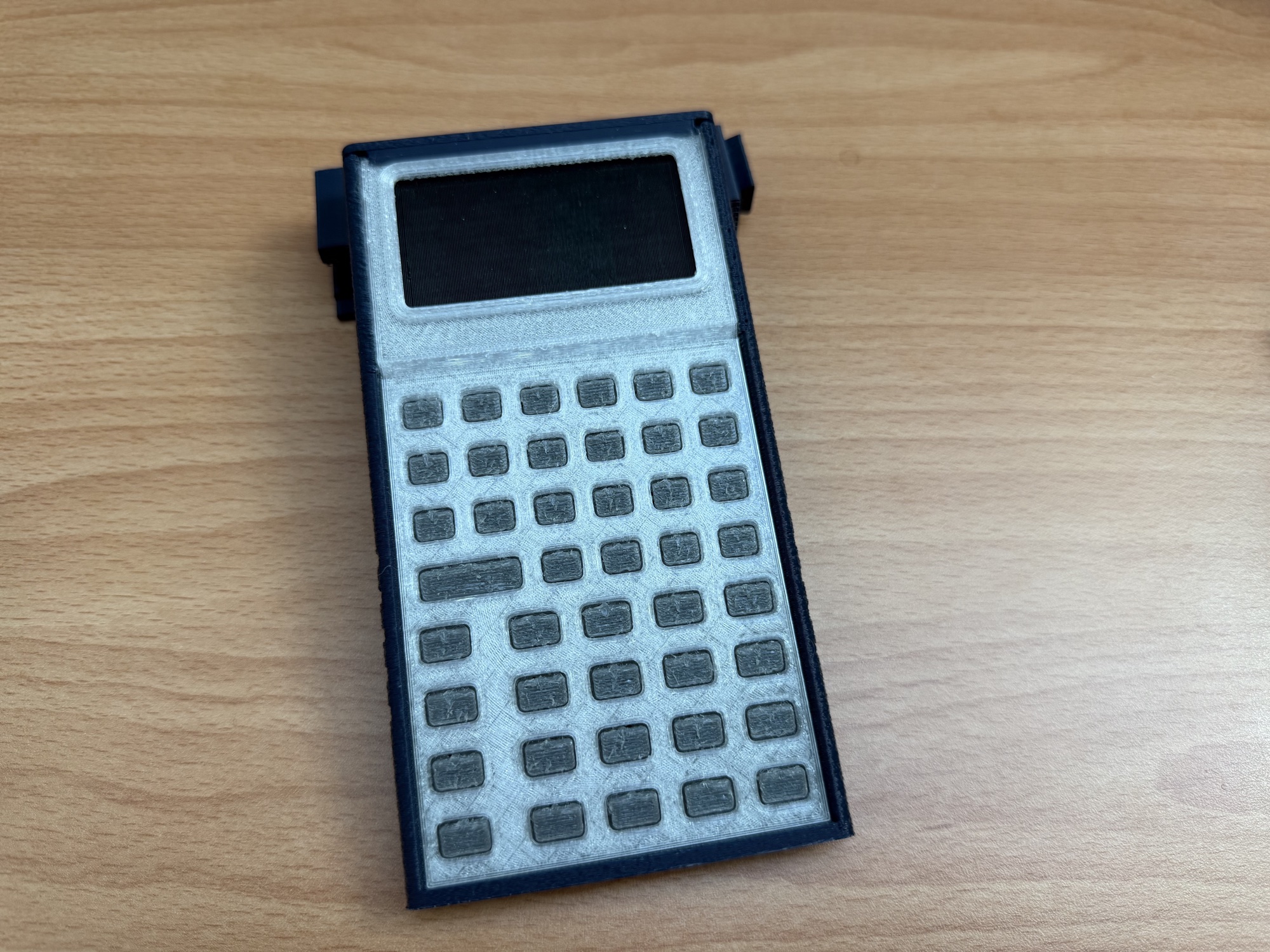
The physical device is a screwless, 3D-printed calculator enclosure. The electronics are an RP2350-based board with a completed KiCad design now in fabrication. The same calculator behavior already runs in the shipping iPhone, iPad, and Apple Watch app and in a browser-based RP2350 firmware emulator.

Printed StackCalc mechanical calculator prototype

What is on the desk now

The current physical prototype is a four-part mechanical assembly: a tapered chassis with internal rails, a unified faceplate, a TPU keypad membrane with a wide ENTER key, and a snap-retained top cap. The parts slide and close without screws, glue, or a separate fastener kit. We printed earlier button fixtures with print-in-place springs, then moved to the TPU membrane because it gives us one continuous alignment layer and a faster way to change key geometry.

The board is not a generic placeholder inside the case. Its KiCad layout fixes the display opening, controller and connector locations, switch layer, and clearances that drive the chassis geometry. The fabricated board is the next physical integration milestone: seat it in the printed enclosure, connect the display and matrix, then compare the same calculator sequences now running in emulation.

What already runs

The companion app is live on iPhone, iPad, and Apple Watch. It shares an RPN calculation model with the project’s other surfaces: values enter onto a four-level stack, ENTER controls the stack transition, and operations consume the visible values. The firmware path compiles the embedded calculator image, feeds it row-and-column matrix contacts, and reads the 132 × 65 framebuffer back from an RP2350 emulator. That lets us exercise key routing, display rendering, state persistence, and idle-loop behavior before board bring-up.
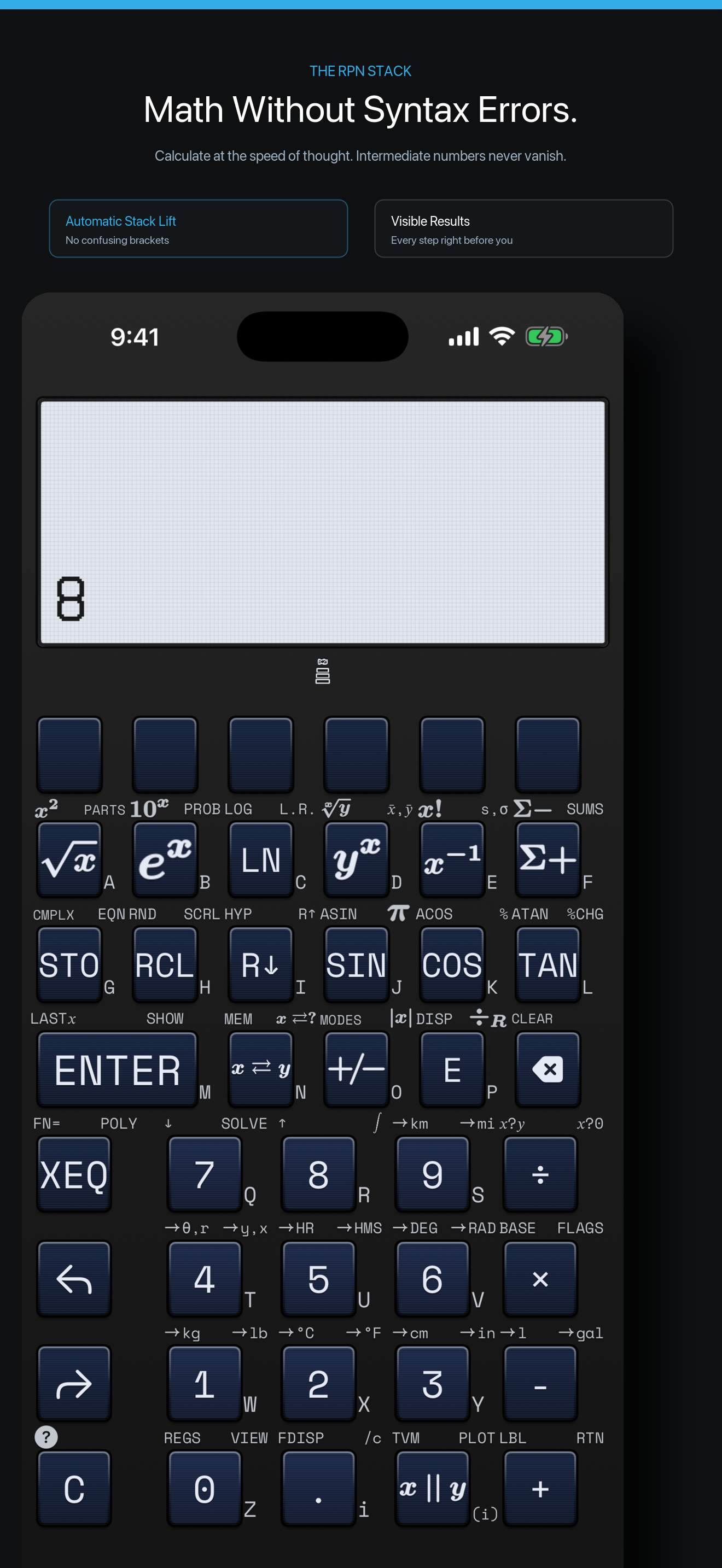
StackCalc iPhone companion app showing the RPN stack

Why the physical design matters

We are not making a retro shell around a phone app. The handheld has to teach the same stack model with its layout, key spacing, screen hierarchy, and physical assembly. That is also why we build the Learning Lab: printable stack tiles, fraction pieces, expression-tree tokens, cards, and teacher materials let someone handle the same sequence they later enter on the app or calculator.

The packaging work belongs to the same problem. We began with a scored-cardboard origami support and evolved it into dovetail-connected printed pieces that protect the kit, form a 78° shelf stand, or become a low 11.6° desk wedge. That gives the calculator a place to live after unboxing instead of leaving the packaging as dead weight.
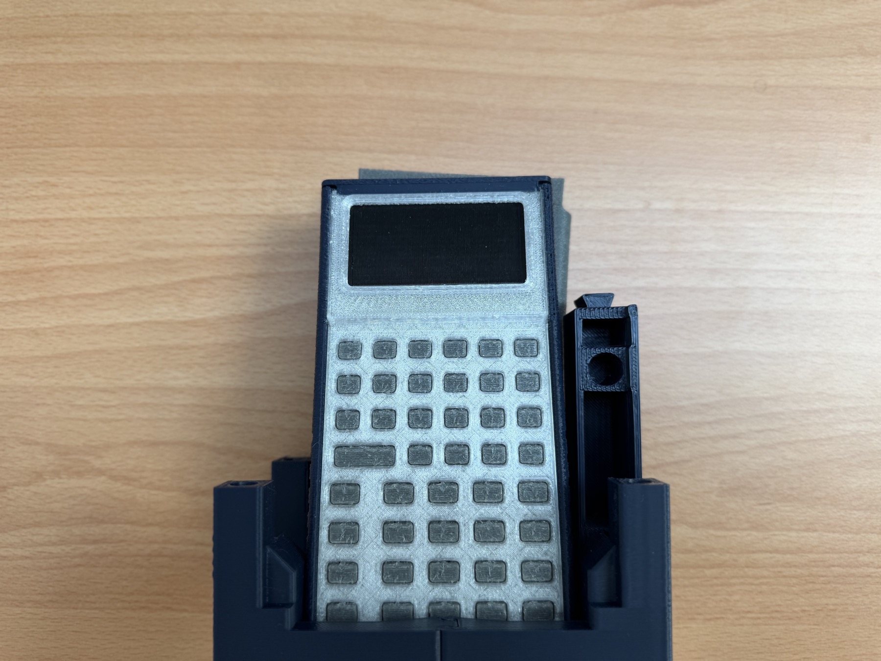
Printed StackCalc prototype in its shelf stand

Build materials and the current record

Current prototype stage

The photographs show unlabelled fit prototypes. Button legends are a separate engraving step after the mechanical iteration, so the blank key faces in these images are intentional. The KiCad RP2350 board design is complete and in fabrication; it is not installed in the pictured mechanical assembly. Watch the 24-second proof reel for the prototype, app, and simulation sequence.

The matching four-part calculator STL set is now available from the StackCalc hardware guide; teacher PDFs and the printable Learning Lab STL pack are also canonical on StackCalc.io. The project Files area carries the matching PrusaSlicer 3MF reference projects, membrane model images, and app walkthrough clips. We keep source code private; the public material focuses on printable parts, teacher resources, visual models, and the design decisions they support.

The first integrated board will answer the physical questions that code and CAD cannot: connector clearance, display alignment, switch reach, matrix behavior, power, and how the printed membrane feels over real hardware. Until then, this project is the build...

Read more »

button_membrane_actuated_case2.png

Modeled membrane deformation at one representative press condition. This is a pre-fabrication simulation using CAD geometry and assumed material and switch inputs; it is not a physical force or lifetime measurement.

Portable Network Graphics (PNG) - 447.02 kB - 09/22/2026 at 23:18

Preview

button_membrane_unpressed.png

Modeled membrane rest state used by the pre-fabrication deformation study. CAD geometry and assumed material and switch inputs only; no fabricated PCB or physical measurement.

Portable Network Graphics (PNG) - 420.10 kB - 09/22/2026 at 23:18

Preview

button_membrane_grid_search.png

Parameter sweep for the pre-fabrication membrane model across modeled press angles, directions, and offsets. It maps model sensitivity and does not validate the current physical assembly.

Portable Network Graphics (PNG) - 416.38 kB - 09/22/2026 at 23:18

Preview

button_membrane_actuated_case1.png

Modeled membrane deformation at a representative press condition. CAD geometry and assumed material and switch inputs only; it is not a physical force or lifetime measurement.

Portable Network Graphics (PNG) - 440.94 kB - 09/22/2026 at 23:18

Preview

button_membrane_actuated_case3.png

Modeled membrane deformation at a representative press condition. CAD geometry and assumed material and switch inputs only; it is not a physical force or lifetime measurement.

Portable Network Graphics (PNG) - 454.81 kB - 09/22/2026 at 23:18

Preview

View all 18 files

  • 1 × 3D-printed chassis Current chassis_award mechanical prototype; material and final production specification remain under evaluation.
  • 1 × Unified 3D-printed faceplate Current unified_faceplate_award prototype part; combines the display surround and keypad openings.
  • 1 × TPU keypad membrane Current tpu_membrane_award prototype part; the present keypad direction after print-in-place spring experiments.
  • 1 × Snap-retained top cap Current top_cap_award prototype part; printed snap features provide tool-free closure.
  • 1 × RP2350 controller board KiCad design is complete and the board is in fabrication. It will be fitted during the next physical integration milestone.

View all 6 components

  • 1
    Build the Current Four-Part Mechanical Prototype

    This instruction covers only the present unpowered, 3D-printed mechanical kit. The RP2350 calculator PCB has not yet been fabricated, so this is a fit-and-assembly guide, not a working-electronics build.

    Parts and source files

    • chassis_award.stl
    • unified_faceplate_award.stl
    • tpu_membrane_award.stl
    • top_cap_award.stl

    Use these four files as a matching set. Do not substitute the exploratory print-in-place spring fixtures or older faceplate variants. Download the matching PrusaSlicer .3mf files from the project Files area. They preserve the model orientation and per-part overrides; open them without rotating or rescaling the model.

    Reference print profiles

    These are the overrides embedded in the supplied .3mf files, prepared for a Prusa MK4S with a 0.4 mm high-flow nozzle. They are reference starting points for this prototype, not qualified production settings. Run a small fit check when changing filament, nozzle, or printer.

    Chassis — chassis_award_petg.3mf

    • Material: PLA, Generic PLA @MK4S HF0.4, 1.75 mm.
    • Structure: 0.20 mm layers and first layer; 2 perimeters; 5 top / 3 bottom layers; 15% gyroid; 0.20 mm elephant-foot compensation; aligned seam; external fuzzy skin with 0.5 mm point distance and 0.2 mm thickness.
    • Support: 5 mm outer brim. Manual snug supports at 35° with a 0.20 mm contact gap and 3 interface layers; supports may begin away from the build plate.
    • Thermal and motion: 225°C nozzle / 230°C first layer; 60°C bed; first layer 40 mm/s; perimeters 250, outer 200, infill 250, bridges 50 mm/s; fan 70–100% after layer 1.

    Unified faceplate — unified_faceplate_award_pla.3mf

    • Material: PLA Silk, Generic PLA Silk @MK4S, 1.75 mm.
    • Structure: 0.15 mm layers, 0.20 mm first layer; 2 perimeters; 6 top / 4 bottom layers; 15% grid; 0.20 mm elephant-foot compensation; aligned seam.
    • Support: No brim. Automatic snug supports from the build plate only at 35°, with a 0.17 mm contact gap and 3 interface layers.
    • Thermal and motion: 225°C nozzle / 230°C first layer; 60°C bed; first layer 40 mm/s; perimeters 250, outer 200, infill 250, bridges 45 mm/s; fan 70–100% after layer 1.

    TPU membrane — tpu_membrane_award.3mf

    • Material: Flexible TPU, AmazonBasics TPU @MK4S, 1.75 mm.
    • Structure: 0.10 mm layers, 0.20 mm first layer; 2 perimeters; 8 top / 7 bottom layers; 15% grid; 0.20 mm elephant-foot compensation; rear seam.
    • Support: No brim. Manual snug supports at 40°, with a 0.17 mm contact gap and 3 interface layers; supports may begin away from the build plate.
    • Thermal and motion: 235°C nozzle and first layer; 50°C bed; first layer 40 mm/s; perimeters, outer walls, and infill 140 mm/s; bridges 40 mm/s; fan 50–60% after layer 4.

    Top cap — top_cap_award_petg.3mf

    • Material: PLA, Generic PLA @MK4S HF0.4, 1.75 mm.
    • Structure: 0.20 mm layers and first layer; 2 perimeters; 5 top / 3 bottom layers; 15% gyroid; 0.20 mm elephant-foot compensation; aligned seam.
    • Support: No brim. Manual snug supports at 35°, with a 0.20 mm contact gap and 3 interface layers; supports may begin away from the build plate.
    • Thermal and motion: 225°C nozzle / 230°C first layer; 60°C bed; first layer 40 mm/s; perimeters 250, outer 200, infill 250, bridges 50 mm/s; fan 70–100% after layer 1.

    Naming note: chassis_award_petg.3mf and top_cap_award_petg.3mf retain historical filenames, but their embedded slicer profiles identify PLA. Use the embedded profile and these settings as the source of truth.

    Assembly

    1. Print the four matching parts from the corresponding .3mf projects. Remove support material carefully from mating surfaces; do not cut or abrade the TPU membrane's flexible features.
    2. Dry-fit the unified faceplate and TPU membrane in the chassis rails. Keep the parts square to the rails and stop if a feature binds; do not force the printed parts into place.
    3. Align the top cap with the chassis catch pockets and press it into the snap-retention features. The cap is intended to close the printed assembly without screws.
    4. Inspect the assembly for pinched membrane material, uneven seating, or stressed snap features. To reopen it, release the retention features rather than prying against the display surround or flexing the chassis unnecessarily.

    Current limit

    There is no PCB, display, battery, or powered calculator in this build. Key force, retention fatigue, service life, and final fit still need measurement on matching physical specimens.

    See the project files for the current exports and StackCalc.io for the source hardware guide.

View all instructions

Enjoy this project?

Share

Discussions

Does this project spark your interest?

Become a member to follow this project and never miss any updates