Introduction:
A Rotovap is extremely useful to have for chemistry but is usually prohibitively expensive for most people to buy (~$500 used and >$2000 new).
This project outlines how to create your own rotovap assuming you have a vacuum supply, wood working tools, and a 3D printer (or just buy printed parts off of a printing service) for less than $100 USD in parts.
Although this rotovap currently does not recover the evaporated solvents like normal rotovaps do, you can easily add a condenser setup and a solvent receiver flask immediately past this setup.
*Disclaimer: Working with glass under vacuum can result in injury, build this at your own discretion*
Parts:
- 1 x PTFE Standard Stopper (This will be the rotary vacuum joint - the most important part)
- 1 x Metal Rod (5.0mm diameter rod, can be found at hardware stores)
- 1 x Pipe (Vacuum Adapter) (7.6mm OD, 6.8mm ID; I got mine from scrap but try checking hardware stores. The ID as long as it's not so small to impede the vacuum can be anything)
- 1 x Glass Transfer Adapter here-in called Flask Adapter (Specifically, mine was a 24/40 Male Joint and 24/29 Female Joint)
- 1 x 25 - 35 RPM high torque motor (Torque is needed to overcome the friction the vacuum puts on the rotary joint)
- 1 x Hinge (Optional if you want to be able to change the angle of the rotovap)
- 1 x 12V PSU (To drive the motor. One could replace this with a PWM driver to adjust the rotational speed)
- 2 x Shaft Bracket (3D printed https://www.thingiverse.com/thing:3770224)
- 2 x Gear Set (3D printed https://www.thingiverse.com/thing:3770224)
- 2 x Flask Adapter Holder (near evaporation flask https://www.thingiverse.com/thing:3770224)
- 2 x Flask Adapter Holder (near vacuum inlet https://www.thingiverse.com/thing:3770224)
Materials:
- Several wood screws
- Epoxy
- Lubricant (Anything that's ABS plastic safe or whatever the plastic used for 3D print is)
- Wood (of various assortment, I basically used scrap wood I had left over from other projects)
Construction:
Because of the variable parts that can be used to make this, I don't have a step by step construction guide or exact measurements but here's the basics of the construction.
*Note: Pilot holes are necessary with thin pieces of wood or the screw will split the wood*
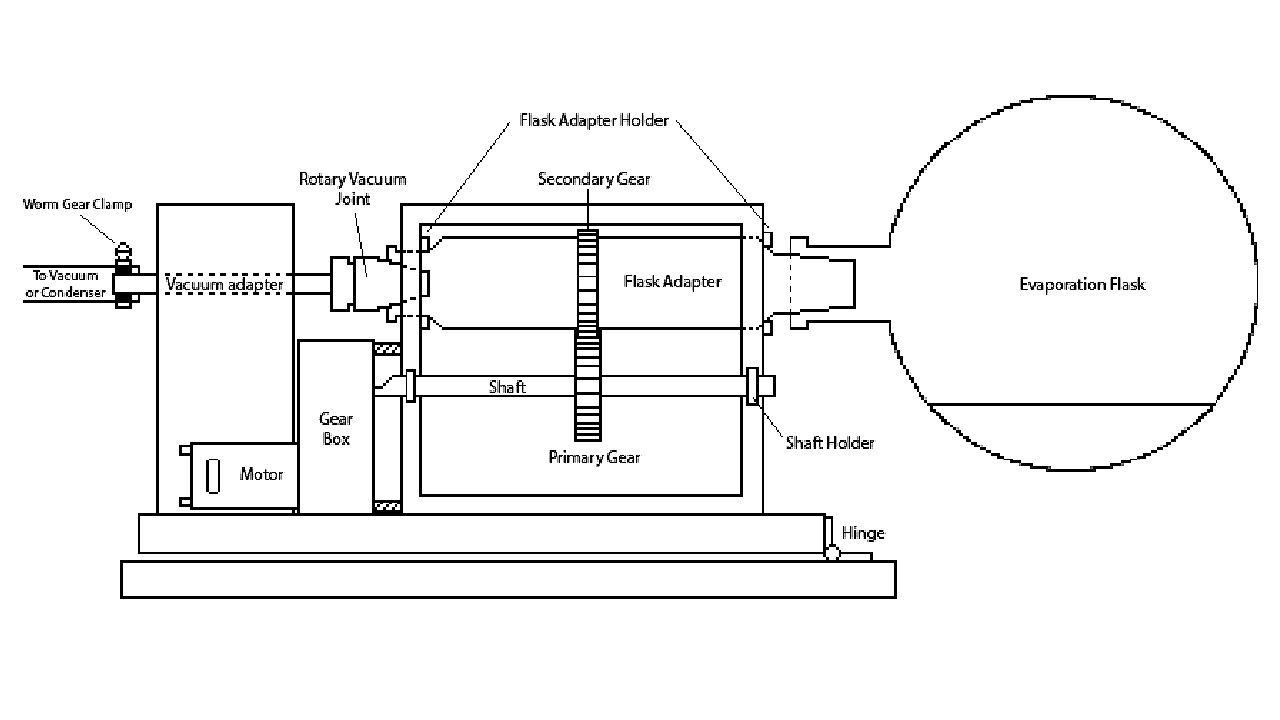
Main Body (Flask Adapter, Gears, Gearbox)
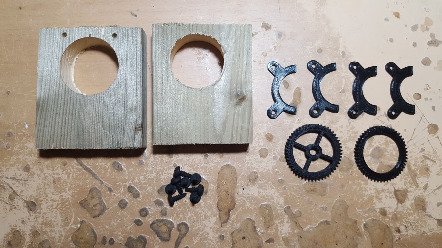
- Buy or print the 3D parts in the parts section. Keep in mind you will most likely need to expand the bracket holes and the primary gear hole as I purposely made them slightly smaller than the shaft to make it fit nicely.
- Mount the secondary gear on the adapter first using epoxy (I used putty epoxy).
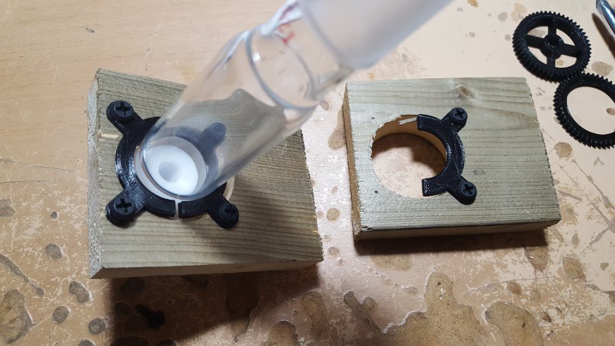
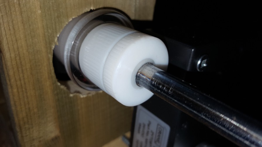
- Create two wooden plank to hold the flask adapter holder making sure there is ample space for the flask adapter to rotate freely in the hole. This hole should be bigger than the flask adapter but less than the flask adapter holder screw holes. Keep in mind of clearance of ~2.3mm between the pairs (top and bottom) of the flask adapter holder to permit easy rotation of the flask (one could print or buy a bearing instead of the flask adapter but this brings complexity not needed with a high torque motor).
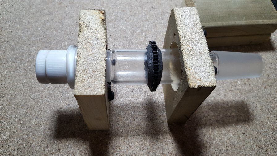
- With the flask adapter in place like the above picture (without the rotary joint), finish off top and bottom of the with wood making sure that the flask adapter can still fairly freely without sliding sideways much.
- Prepare the gearbox so that it can properly couple with the shaft (my gearbox has a D-Shaft/Half moon which fit the shaft nicely once ground down to the proper D shape).
- Get the primary gear on the shaft and flank it with the two shaft bracket. With the two brackets near the two respective edge of the wooden flask adapter (see the diagram) and the primary gear positioned in line with the secondary gear, slide the brackets along the wood until the two gears mesh (This may take some time to get right and make sure that the gears mesh but too tightly and the gears may freeze when rotating. Because of the imprecise nature of the build for ease of build, slightly loosely meshing gears are needed for the gears to rotate).
- Once you position it just right, use a marker to mark the locations of the shaft bracket holes for the pilot holes.
- Move the primary gear to mesh properly with the secondary gear and test to see if a complete rotation can be achieved. If satisfied, epoxy the primary gear onto the shaft.
- Mount the gearbox/motor and couple it with the shaft
Rotary Vacuum Joint
- Disassemble the PTFE Standard Stopper and the rubber O-ring
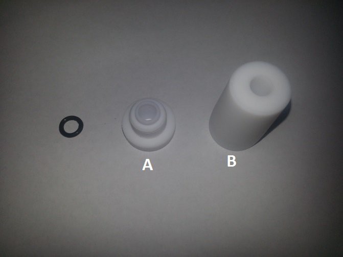
- Grind down the threads on both part A and B
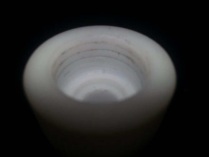
- Dig out a channel for the O-ring and reattach the O-ring
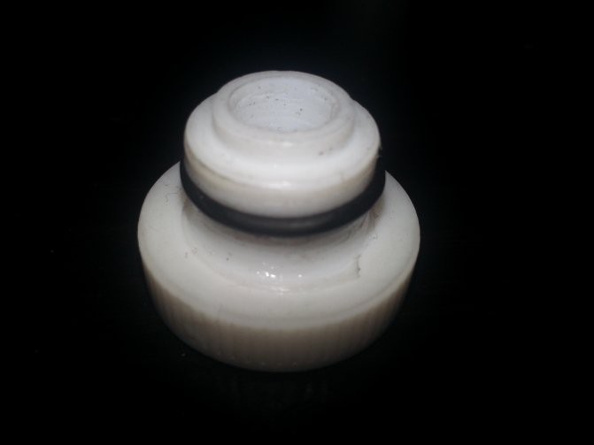
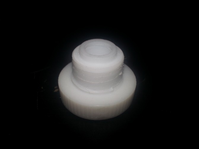
- Lubricate the O-ring and reattach part A to part B. Make sure both pieces rotate fairly freely. If not, you'll need to either do a better job removing the threads or deepening the O-ring channel.
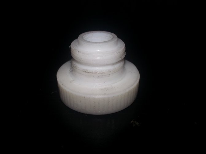
- Add epoxy to the vacuum adapter and push it about half way down into the part A.
Combining the Body and Rotary Joint
- Fix the body onto a piece of wood that will be the base of the rotovap.
- Attach the rotary joint to the flask adapter.
- Make a hole in a block of wood that can fit the vacuum pipe. Make sure it's also tall enough to sit on the base of the rotovap.
- Push the vacuum adapter into the hole in the block. Mount the block onto the base of the rotovap.
- Epoxy the vacuum adapter to the block so it remains stationary while the flask adapter can spin.
Performance
I still need to run some performance test to see how well it evaporates other solvents at higher temperatures.
Preliminary results show that it will evaporate 42mL 95% anhydrous Ethanol in 1 hour in a 23°C water bath.
Final Remarks
Although I provided some construction guides, this rotovap can be build with anything and any form as long as it can spin a flask with sufficient torque. The most important part of the rotovap in my opinion is the rotary vacuum joint which I've struggled to find a cheap design until I found cheap Teflon stopper.
Hopefully this guide helps some amateur chemist in building their own rotovap!
(I really broke the formatting and now can't erase those two bullets below :S )