 Rob Smith
It premiered at the UK Kickstart Expo this year, and I'll be honest, I only got it working properly the day before!
It can't play every MOD file (what is a MOD file), and there's a couple of reasons for that. The main one being the physical time it takes for the camera to jump around the disc. That'll make more sense in a bit.
First, a quick demo...
If you'd like to see this in real life, I'll be taking it to the Retro Computer Museum (Leicester, UK) on the 5th Decemberfor one of their special events.
Part 1 - The Discs
Let's start with the discs themselves, because it's not entirely obvious what's going on when you look at one.
 Click for High Res Image
On the front there's this circular pattern, and at a quick glance it almost looks like how a disk would be laid out with tracks and sectors. Well, that's not entirely incorrect. Get in really close though, and you can see it's text. Each ring contains patterns from the MOD file, printed row by row, with the four sound channels squashed together with no spaces, each one split into note, sample number, effect and effect value.
I wrote some Python that takes a MOD file, pulls out all the patterns, and draws them radially onto one enormous image rendered at 1200dpi. The text uses a modified version of the Amiga Topaz font. The modifications make it easier to tell apart characters like 8 and B, which otherwise would very easily be mistaken for each other. You'll see why that matters later.
Down the left edge of every row is a number running from 0 to F and then repeating. I was always worried I'd never get the disc positioned perfectly, so knowing which row was in the centre of the camera's view seemed difficult. This gives it a clue. You might be wondering why I didn't just write 0 to 63 like a normal person. Well, the disc is designed to be the same size as a 12" vinyl record and I just didn't have the room, especially with the spacing needed to keep each ring obviously separate from the next.
The font size was an experiment. I basically kept shrinking it until the printer couldn't print it accurately anymore. And yes, I bought a new printer for this, my very old one didn't stand a chance at this resolution. The problem is the printout is bigger than A4, and buying the new printer was expensive enough without going for an A3 1200dpi laser, so instead the image gets split into three A4 sections. That's why there's what looks like wasted space on the disc. With 63 patterns it balances nicely and cuts into three pieces easily. You can fit 65, but cutting that out was time consuming and prone to errors, and most MOD files have fewer patterns than that anyway.

I also realised very short MODs will fit on a 7" disc, which prints from a single A4 sheet. These are much easier to make and tend to play much easier too.
The back
So that's the front. What about the back? First I had to work out what actually needed storing, and it turns out it's the first 1084 bytes of the MOD file. That's the song name, the details of the 31 samples (length, finetune, looping), the play sequence and the M.K. marker. After that would normally come the patterns, but they're printed on the front, so that just leaves the sound samples.
I had loads of ideas for this, including physically printing the waveform of each sample, but there was no way that was going to sound good enough. So I went digital, which meant coming up with a barcode.
Designing a Barcode
There's loads of barcode formats out there already, but most are built to be scanned at weird angles in all sorts of conditions. That makes them very robust, at the cost of how much data they hold.

Take a QR code. It has finder patterns so it can be located mid-air, an alignment pattern so rotation, skew and distortion can be corrected, white space around the finders, timing patterns to work out the grid size, format information describing how much of the rest is error correction, the actual data, a big chunk of Reed-Solomon error correction, and even a "dark module" that's always black so the scanner knows what black looks like.
Now I don't need anything that complex, because I have an advantage. I know the camera will always be pointed straight at the surface, almost parallel to it, looking at a known shape with space around it. So no finder patterns, no separators, no alignment pattern. I'll only ever have one format, so no format marker either. And I control the camera and the lighting, so the dark module can go too. That leaves timing patterns, data and error correction.
Printing square codes onto six equally sized rings would waste a lot of space, so instead each code is a long thin grid, 118 dots wide by 25 dots high. The scary thing is each dot is around 0.17mm. You can fit just under six in a millimetre. It's very small, but it still prints properly.
That gives 2,950 bits per barcode. Each one holds 276 bytes of payload. I wanted Reed-Solomon error correction, but that has a limit of 256 bytes, so the payload is split into two blocks of 138 bytes. Then comes the bit that might seem strange. The two blocks get interleaved, so every other byte belongs to the other block. This is actually important. If part of the printed code gets damaged, it's less likely to wipe out a whole block, and more likely to damage a small part of both, which gives the error correction a much better chance.
Each block gets 36 bytes of Reed-Solomon, meaning up to 18 mistakes per block can be corrected before the data is unrecoverable. Those are interleaved too.
The layout ends up as:
- An alternating clock pattern around the edges to work out the size of the code
- A magic number, 0xA5 0x5A, interleaved across both blocks
- The ring number, once per block
- The barcode sequence number, once per block. Having these duplicated is handy, it's another check we can do.
- The 276 bytes of payload
- The Reed-Solomon data in the remaining space
The observant among you might notice two bits left over. It doesn't divide into 8-bits exactly, so they're just not used.
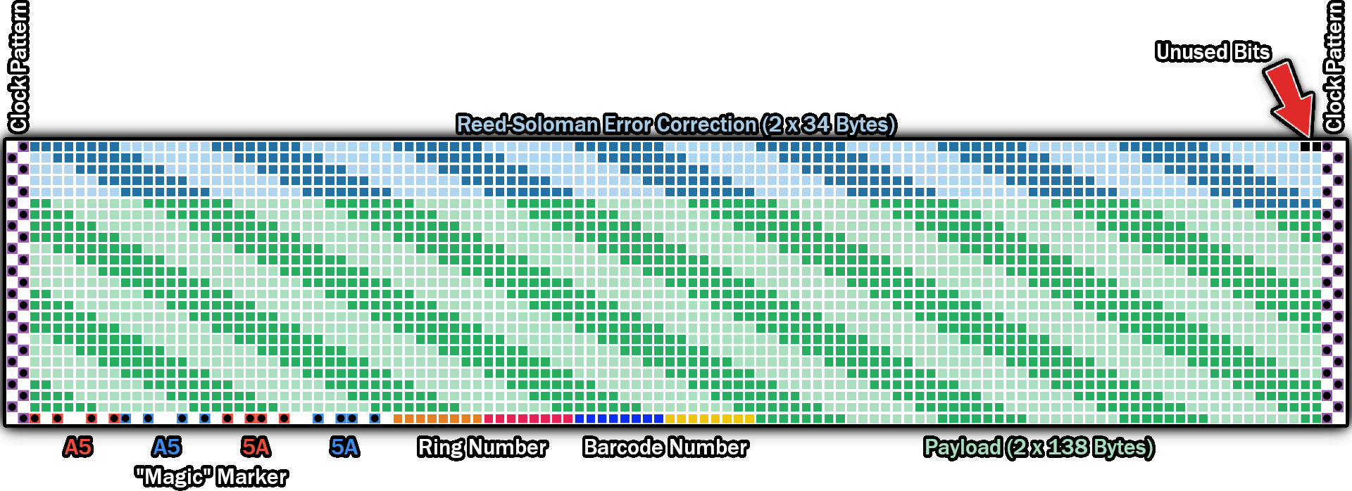
One more thing, each dot is printed with a little white border. This was an experiment, but it stopped the printer bleeding neighbouring dots into each other and made the codes much more reliable.
Oh, and I've since done a version 2, which adds timing dots along the top and bottom edges too. That made decoding a lot easier.
Fitting the samples
Across the six rings (numbered 0 to 5) that's around 142KB, with each ring able to hold more than the one before it. That's not much, and plenty of MOD files are far bigger than that. So how do the samples fit?
Well, this is the sneaky bit. The encoder compresses each sample using the Opus codec, starting at 64kbps. When it's done, it checks the total size. Too big? It re-runs at 32kbps and tries again, and keeps dropping the bitrate until everything fits. Given these are 8-bit samples to start with, you probably can't really tell.
Assembling a disc
The 12" platters are 3D printed, but they're too big for my printer, so they're printed in six pieces, three each side, glued together into a blank platter. Then the three printed sections for the front are cut out, lined up, stuck together and stuck onto the platter. It doesn't need to be very precise as long as it's roughly aligned. The barcode side is much harder, because it's very easy to cut straight through one of the codes.
The following video goes into more detail about everything above.
Part 2 - The Hardware
Like most of the crazy things I build, I designed the whole thing in 3D first. The basic shape stayed the same throughout, but the camera housings got redesigned several times, partly because I had to change cameras completely. More on that shortly.
Motors
There are three identical stepper motors. Two move the cameras along linear rails using timing belts, and one spins the disc.
Attached to each motor is an AS5600 magnetic encoder, which can sense the angle of the shaft to around 0.08 degrees. Each board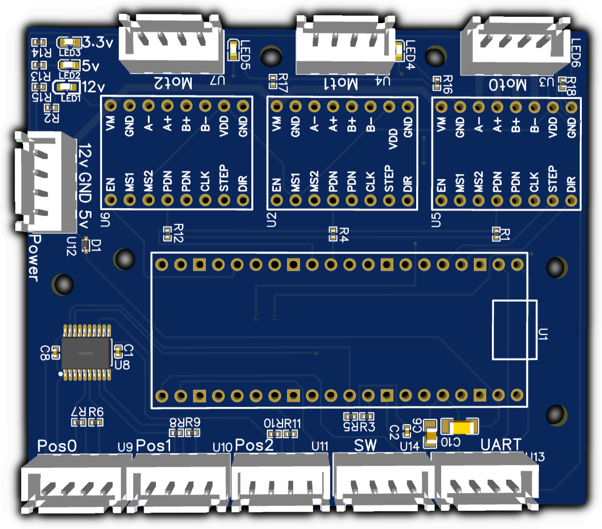 comes with a tiny magnet that needs gluing to the back of the motor shaft. That isn't easy, so I printed a little holder that kept the magnet in place while the glue set, without getting stuck itself.
Why bother? Steppers are great for precise control. The ones I'm using are 200 steps per revolution, and the TMC2209 drivers can do 256 microsteps, so 51,200 steps for a full rotation, and they run quieter too. The downside is if you spin something heavy like this disc and try to stop it instantly, the motor can't hold it and it skips. You can literally hear the spindle snap into the next position. Same if you try to spin it up too quickly. With the encoder, even if it skips, I still know exactly what angle it's at.
There's also a pair of limit switches for homing the cameras. On startup both cameras move left fairly quickly, hit the switch, back off and repeat it slower for accuracy, then race off to the other end to check the full travel.
All the encoders are I2C, but they all answer to the same address. So there's a TCA9544A in there, which splits the I2C bus into four, letting me pick which encoder I'm talking to. All of these are neatly connected on a single PCB controlled via a Pi Pico.
The rest of the outside
On the front is a 40x4 dot-matrix LCD. I thought the LCD would give it a pixel feel rather than just sticking a little monitor on it, and the blue backlight fits nicely with ProTracker. There's a translucent strip with addressable RGB LEDs behind it for the spectrum analyser, and two 15 watt 8 ohm speakers, bigger than anything I've used before.
What look like speakers on the sides are actually fans, one in and one out. They're 12v fans running at 5v, with a temperature monitor to speed them up if it gets too hot.
Round the back there's volume, an audio out jack, a USB3 header so I can get at the insides without opening it, a small touch screen for monitoring and controlling the system, a power button, 12v in, and three buttons: Play, Stop and Mount/Unmount.
The VU meters
The VU columns are pushed up and down by servos with printed cogs, meshing with a row of teeth along the side of each column. I designed them with enough teeth for the full 180 degrees of the servo. Unlike my floppy disk cleaning machine, I wanted nothing glued in, which was handy when I crunched a gear in one servo and just unscrewed it and swapped it.

At the bottom of each column is a WS2812 LED, chained together so all four are controlled from one wire, and the colours change as the column rises. I pulled the colours out of ProTracker itself. I tried a solid column (light didn't travel up enough), a cone (looked weird), transparent resin (didn't print right and I didn't have time to dial it in), and finally went with a hollow design, which spreads the light really well.
The brains
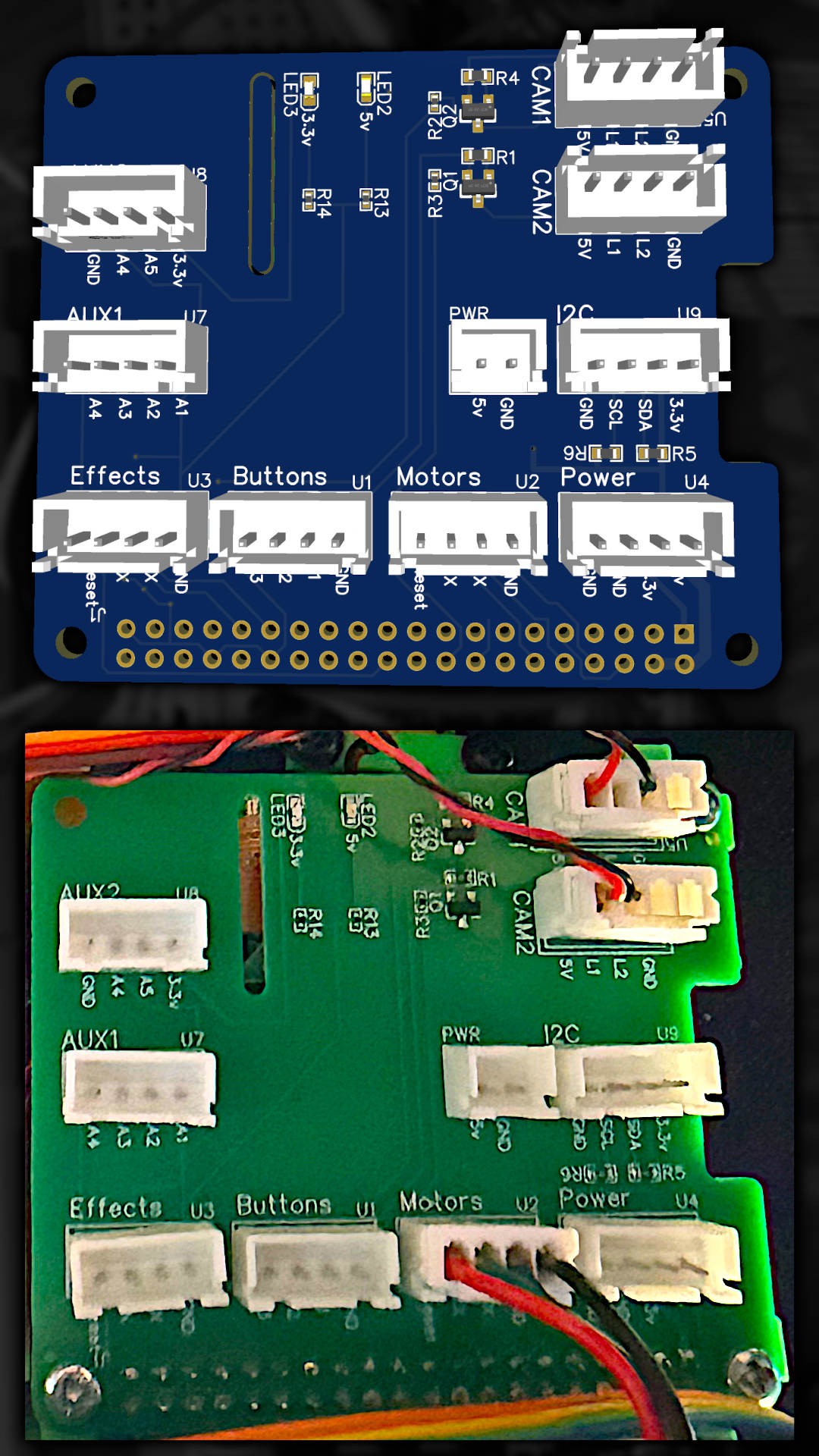
At the heart of it is a Raspberry Pi 5 with a custom hat. Then there are two Pi Picos. One's sole job is running the motors, with the three TMC2209 drivers, encoders and limit switches. The other handles the LEDs, servos and the LCD, with a couple of level shifters to get the 3.3v I2C up to the 5v the LCD needs, and a buffer chip for the WS2812 data line.
Both Picos take simple text commands over serial, terminated with a line feed, like "spin the disc to this angle". Almost everything is output using PIO fed by DMA, which keeps everything running smoothly. I highly recommend splitting your I/O out like this rather than trying to do it all from the Pi. It makes things much easier to manage, and I could test everything from a serial console.
One gotcha. The effects Pico kept locking up randomly and I couldn't work out why. I thought it was power spikes from the servos, but isolating those didn't help. Eventually I realised some MOD files had exclamation marks in their song or sample names, which I was sending to the LCD. Unlike the other commands, that symbol was checked for wherever it appeared, and it was dropping the Pico into programming mode. A real face-palm moment.
In the base there's a 12v to USB-C PD 5v supply so the Pi doesn't complain about low voltage, a 15 watt amp that's really great, an audio isolation transformer (there's ground loops in there, and without it you get loads of buzzing through the speakers), and one more 12v to 5v supply.
Cameras
I started with the Arducam OV2640, a 2 megapixel camera with an onboard buffer, controlled over I2C with images pulled off over SPI. It proved the idea was viable, and I went ahead and designed housings for it, despite the terrible documentation and broken examples. It wasn't until I tried to use them in real time that the problems started. The fastest I could get was 10fps at 640x480. Too slow, too low resolution, and I couldn't control the exposure how I needed.
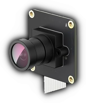
So I switched to the OV9281. Some people assumed that was an expensive camera, but it's actually very reasonable. It's black and white, does up to 309fps at 640x480, and gives you direct control of settings like exposure, so you can take a very quick image and avoid motion blur.
Most importantly, it's a global shutter camera. Most cameras, like the one in your phone, are rolling shutter, they scan the image top to bottom one line at a time. Fine most of the time, but with fast movement you get tearing because different parts of the image are captured at different moments. A global shutter captures every row at once. With a very short exposure, I can capture the disc spinning at 70rpm at 60fps and a freeze frame is as sharp as a photo. My phone filming the same thing at its lowest exposure with as much light as I could give it is just a blur.
These connect over the Pi's MIPI interface, and the Pi 5 has two of them onboard, which is exactly why I went with it. They literally just worked out of the box. Housing them was another story. They're bigger, the first design was so wide it couldn't see everything at the extremes of travel, and I had to move them closer to the disc. Ironically, I ended up using the lenses from the old cameras as they gave a better picture up close.
For a detailed explanation of how stepper motors and global shutter cameras work, and how all of this comminicates, check out the following video:
Part 3 - The Software
Lighting
Before reading anything, the lighting needs sorting out. The LEDs don't light the surface evenly, and it needs to work in different rooms. There's a calibration disc with two plain white paper sections on it. Take a few frames of that, average each pixel, and you can use that to remove the lighting bias. Not perfect, but a lot better.

That doesn't fix room lighting though. Shine a torch on it and the output changes considerably. So each image gets normalised, and this is incredibly easy. Find the brightness where 2% of pixels are darker, and the brightness where 98% are darker. Anything below the first becomes black, anything above the second becomes white, and everything in between gets stretched across the range. Now it barely cares about me shining a torch at it, unless I get so close I create hot spots that can't be corrected for.
Reading barcodes
The captured barcodes look nowhere near as clean as the originals. You might think sharpening would help, but we don't want to add detail that isn't there.
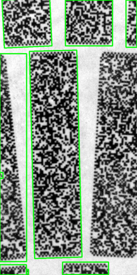
So we do the opposite and apply a very subtle Gaussian blur, which removes high frequency noise from the camera. Then a threshold is calculated on small sections of the image rather than the whole thing, as a mostly white image would throw it off.
The computer still doesn't know where the barcode is though. QR codes have finder patterns for this, but I have a lot more control over where the code can be, so I use OpenCV's findContours, which finds connected areas and draws outlines around them. That finds the barcode, plus a load of stuff we don't want. So anything too small, not wide enough, not tall enough or too tall gets thrown away, along with anything touching the edge of the image, as it's probably not complete. That usually leaves one, maybe two boxes. From there we work out the angle, rotate it flat, cut it out, use the timing dots to find each row and column, read every dot, and run Reed-Solomon over it.
Images are queued up and decoded by up to three processes at once, which is why it can spin the disc so fast while reading the back.
Reading patterns
The front has a special black marker on pattern 0. The disc spins until it finds it and rotates so the first row is roughly horizontal. That's zero degrees. Because I created the layout, it now knows roughly where every pattern starts and ends and which ring it's in.
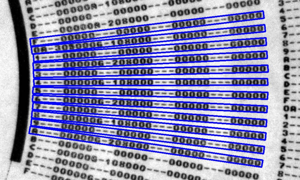
When a frame comes in, the encoder tells us the current angle, so we know which pattern we're in and roughly which row is in the middle. There's a delay between reading the sensor and that reaching the Pi, and this is where that 0 to F column comes in. The encoder is close enough that the column can correct it.
Then it's findContours again. Tiny boxes and anything overlapping the edges are removed, broken characters (like an F that got split in two) are merged based on their position and angle, and anything that's too big, too small or clipped gets thrown out. Then each row is cut out and rotated flat, and because it's a fixed format, split into individual characters.
OCR
Now, you might think this is easy. OCR has been around for a very long time. But most of it isn't designed to work in real time, and I knew from the start I'd have to roll my own.
I tried several pattern matching methods against the original font and they were all incredibly unreliable. So instead I took six images from different rings of a printed disc, extracted the rows, and wrote down by hand what every character should be. Then I saved every character out to a folder tagged with what it was. Over 2000 images by the end.
These were fed into a Support Vector Machine. It doesn't memorise the images, it learns what makes one character different from another. Give it one it's never seen before and it returns a confidence score for every possible character. We just pick the highest.
That's not the whole story. To know which row of which pattern a character belongs to, we combine the partial row number from that first column (which may or may not be right), the approximate middle row from the encoder, and the order of the rows, allowing for any that were missed. Together that gives a very high confidence.
And because the disc spins at the same rate the pattern plays at, we see each row many times. So for every character in every row of every pattern, the confidence for each possible character is kept and updated, and the more times it's read, the more likely it is to be right.

There's one more sneaky trick. Pattern data has rules:
- Note columns can only be a dash or A to G
- Sharp columns can only be a dash or a hash
- The octave can only be a dash or 0 to 4
- The upper digit of the sample number can only be 0 or 1, as there's only 31 samples
- Everything else is hex, and can't be a dash, hash or G
If the OCR says something that can't possibly exist in that position, we just throw it away.
It still wasn't very accurate at first, because the training data was fairly small. So I made a training disc with a known sequence printed on every row. The OCR was good enough by now to work out which row was which, so the disc could automatically generate loads more training data. Retraining on that vastly improved the results.
The J.I.T. MOD player
So we can read the back, and we can read the front, but how does it play in something close to real time?
Actually playing a MOD is easy. Well, kind of. I converted an old MOD player I wrote in Pascal many years ago into Python and fixed up some of the odder ProTracker behaviours. Once the back of the disc has been read, it builds a MOD file in memory with blank patterns and loads it into the player.
And here's the sneaky part. There's actually two MOD players.
The second is a cut-down copy that only follows a few rules. It knows the play sequence, set speed (F), pattern break (D), position jump (B), pattern loop and pattern delay. Rather than playing each line, it asks for it. The disc spins to that line, reads it and the lines around it, and fills in whatever pattern data it can. It keeps working through the song like that with one rule: stay 3 seconds ahead of the real player. As it does all this just in time, I called it the JIT MOD player.
The real player just plays normally, except before each row it checks if the data is there. If not, it deliberately hangs on the current row until it is. That makes a noticeable audible effect, which honestly adds to the magic of watching it. And because the JIT player follows all the timing rules, it knows how long each row lasts, so it knows how fast to spin the disc to keep up.
And somehow, all of this craziness worked!
For a more detailed summary of all of this, check out this video:
Part 4 - ...but can it Pattern Skank!?
Right from the first video my goal was to get Pattern Skank by h0ffman playing. If you've ever looked at the play order in a MOD file you'll know they don't always run in order. Sometimes they jump all over the place, and when you're pulling off crazy effects they can jump on every line. In one section of Pattern Skank the position and pattern change three times in a very short space of time, which means the disc and camera have to fly all over the place.
The problem commands are pattern break, position jump and set speed. Pattern Skank uses set speed constantly, and in places combines pattern break and position jump. Misread one of those, or even its value, and anything could happen.
So since the first version, I've:
- Rewritten the motor driver so it no longer overshoots wildly when seeking, and streams the position constantly instead of a slow request/response loop.
- Retrained the OCR, after discovering I'd accidentally only been feeding half of the training disc into the training. Oops. Much more accurate after fixing that.
- Fixed a JIT bug that skipped pattern break in certain situations, causing the audio to stall until the real player caught up.
- Snapshotted each line when the JIT finishes it. The JIT keeps re-reading and improving its guesses, so a line could change between the JIT processing it and the player playing it. If, say, an A was misread as a B, the player jumps to a different position while the JIT carries on where it was, and they're completely out of sync.
- Made it require higher confidence and more re-reads whenever those three risky commands appear.
- Overclocked the Pi to 2.9GHz from the stock 2.4. It wasn't stable at 3GHz.
- Compiled the whole Python program into an executable. People accuse Python of being slow, but if you use its fast built-in ways of doing things instead of loops, most of your code is running compiled anyway. Some bits, like the motor logic, just can't be done like that.

The big problem left isn't misreads, it's that the JIT player can't always stay 3 seconds ahead. Taking more pictures to improve confidence takes time, and with a MOD that plays fast or jumps about a lot, that becomes a real issue. Every time the disc has to move to a new position, that's roughly another second unaccounted for. Lower the confidence required and you just get bigger problems.
So, can it play Pattern Skank? Not too bad! I don't think I'll ever get it perfect, but that kinda isn't the point. A few glitches along the way add to the fun and performance of the thing, and on the whole I'm really happy with it.
Oh, and the Quadrascope
I couldn't leave it alone. I always wanted ProTracker style quadrascopes on the original and never had time, so there's now four tiny LCDs driven by another Pi Pico. They're not the fastest to redraw, so the Pi sends 240 samples for all four channels in one go, and the Pico renders one column at a time across all four screens using DMA. By the time it's got round all four, the first has probably finished drawing anyway. This one just plugs into the Pi's USB and shows up as a serial port, which kept it nice and modular.
The servos have also been replaced with metal geared ones, now just pushed in and held with a strip of plastic so they're easy to swap, and there's a few cosmetic covers to make it look a bit more like a finished product.
This thing has taken up way way way too much of my time, and I think it's time to move on to something new.
And to see a summary of all of this, and final testing with Pattern Skank, watch the following:
And a few more demos...