Close
0%
0%

"LoRaLAN" - Local only, LoRa sensor network

I got tired of short-range sensors so I built a LoRa receiver that forwards sensor data to only my local wired network

Similar projects worth following
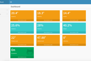
Introducing LoRaLAN. 100% local, long range base station which forwards LoRa data to an Ethernet or Wifi network. This started because Zigbee and Wi‑Fi didn't have the range for my property and LoRaWAN / TTN / ChirpStack felt like overkill for a simple sensor network. So I built a dual-Pico bridge that forwards LoRa packets to a websocket. The packets are tagged per sensor so they can be sorted and processed on NodeRed — no cloud required. Sensors are one way today; control later. Full origin story, photos. Firmware: https://github.com/scottlecomte/Lora-to-Ethernet-Bridge

Anyone else get annoyed that “smart” or "IOT" usually means send your data over the Internet to a cloud service?

How about constantly fighting with Zigbee or Wifi sensors thats range is horrible?

This didn’t start as a grand plan. It started because the off-the-shelf stuff wouldn’t cover the sensors I needed for my property and I was tired of sensors that needed an Internet connection to work properly. 

First try was Zigbee. Inside the house those window/door sensors are fine. Out on the property? Range made them useless (yes, I added extenders). I dealt with flaky links and there were several spots that had zero signal.

So, I switched a bunch of things to Wi‑Fi. Longer reach, and bonus: I could ping stuff with normal network tools and see if it was still alive for a heartbeat. That worked okay for many sensors but a couple of locations still sat outside Wi‑Fi range like they were mocking me.

Then I found LoRa. Low power, long range, “up to ten miles or more” depending on who you ask and how optimistic they’re feeling (and what lies between the nodes of course). The catch, according to everything I read, was that two nodes can talk peer-to-peer, but if you want *many* nodes you’re supposed to use LoRaWAN.

That sent me down the Things Network / ChirpStack rabbit hole. The Things network was right out since it was yet another cloud platform that didn’t need to know how cool I keep my office. ChirpStack was an option as it can run on your own local server or in a container, which sounds great, but the whole stack still felt like way too much complexity. Buy an expensive LoRaWAN gateway (they weren’t cheap when I looked). Wrestle the gateway onto ChirpStack. Register every sensor by its DevEUI (basically the device’s unique ID). Hang each one under a custom application. For “is my gate open” and “what’s the soil doing,” that was way too much to do for simple sensors.

So, I did the easiest thing instead. Bought a couple Raspberry Pi Picos and some RFM95 modules, fired up MicroPython and a RadioHead-style stack on the receiver and the sensor node, and added addressees to both in the code.  It worked! I then built a few sensors to monitor temperature and humidity. Watching packets show up on a serial terminal attached to the receiver was a solid dopamine hit. Also, completely useless for capturing data for home automations.

I needed those packets on the network where the automation lives.

My first bridge that actually worked was a Pico W forwarding sensor packets over WiFi to MQTT. This was a great achievement in my eyes. I wanted to keep the data off WiFi as much as possible as I thought it added one more layer of un-needed complexity. I also wanted the data straight into Node-RED, where I could sort it and decide what happens next — write it to the database, send it to MQTT for Home Assistant,  or whatever — without another radio hop onto Wi‑Fi if I can help it.

Around the same time, it clicked that all of this could be used in the real world, not just my property. A lot of businesses treat Wi‑Fi as an external / untrusted network for security reasons. So that really pushed me to create a wired Ethernet gateway. This could be very useful in a rural farming environment as well and I know the LORAWAN people were pushing that pretty hard. Probably because they wanted to collect and sell their data. Yeah, I said it.

So the bridge I run now looks like this:

RFM95 → Pico (LoRa RX) → UART @ 230400 → W5500-EVB-Pico → Ethernet → Node-RED WebSocket

The Pico uses the RFM95 to listen for LoRa packets and frames packets over serial to the Wiznet W5500. The WIZnet board opens a WebSocket to Node-RED and forwards those LoRa payloads over Ethernet. Inside Node-RED the packets can be sorted using the sending nodes address, and sent through custom flows. The gateway has built in connection recovery when Node-RED redeploys and drops the web...

Read more »
  • 1 × Raspberry Pi Pico
  • 1 × Wiznet W5500-evb-pico
  • 1 × Custom PCB
  • 1 × RFM95 LoRa Module

  • LoRaLAN WiFi Gateway: a second way into Node-RED

    Scott LeComte • 11/04/2026 at 15:47 • 0 comments

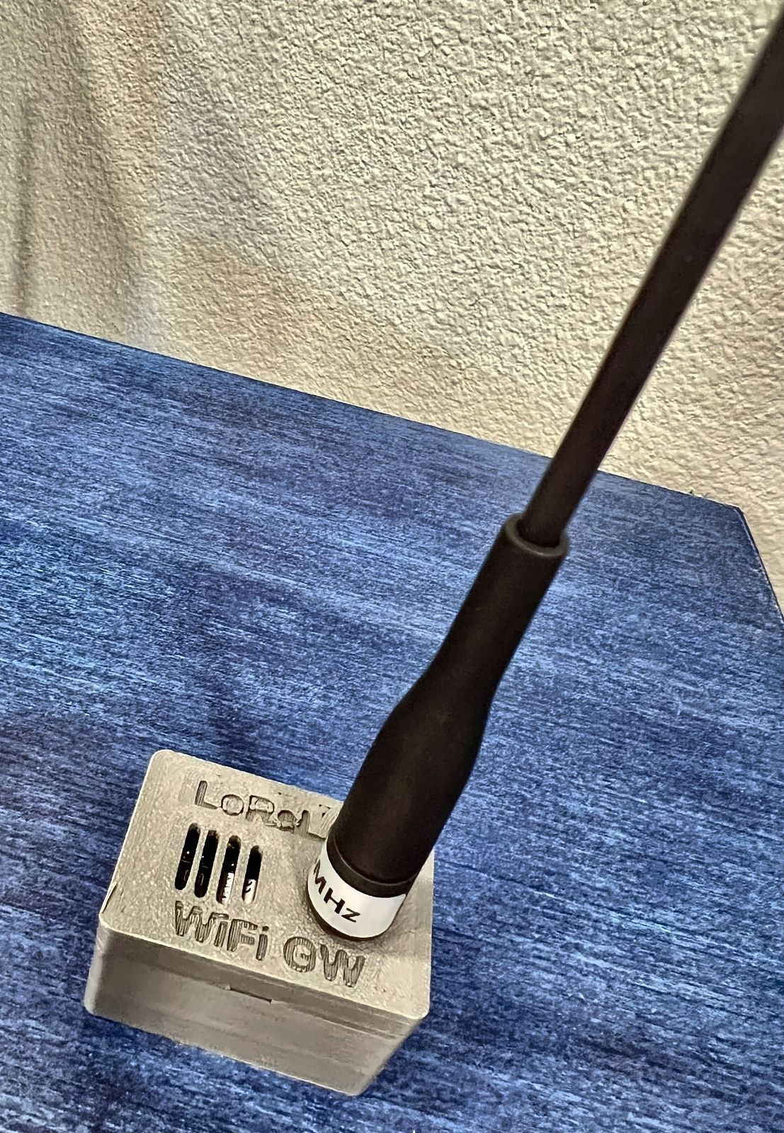
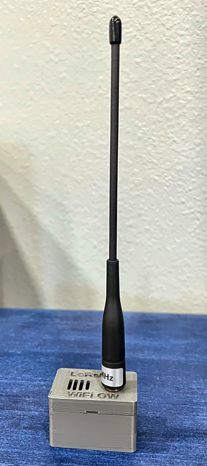
    LoRaLAN has a new gateway. The LoRaLAN WiFi Gateway does the same job as the Lora to Ethernet Bridge, but over Wi-Fi: it listens for LoRaLAN sensor packets on 915 MHz, ACKs each one, and publishes it to an MQTT broker in the same JSON format the bridge sends Node-RED (with a gw field added). Same radio settings, same RadioHead-style packets, so existing nodes work with it unchanged. The network overview is in the LoRaLAN repo.

    What it's for If you have a Wi-Fi network and LoRaLAN sensor nodes, use it as your main gateway with no Ethernet run, or put it closer to far-off sensors to extend their reach. Your Node-RED server and MQTT broker must be reachable on the Wi-Fi network it joins. You can run several gateways at once, mixing Ethernet bridges and Wi-Fi gateways, to greatly expand range. Each gets its own address, and every message says which gateway heard it. Over a VPN, a Wi-Fi gateway at a remote site can publish to your broker at home, so you can monitor remote locations across the Internet.

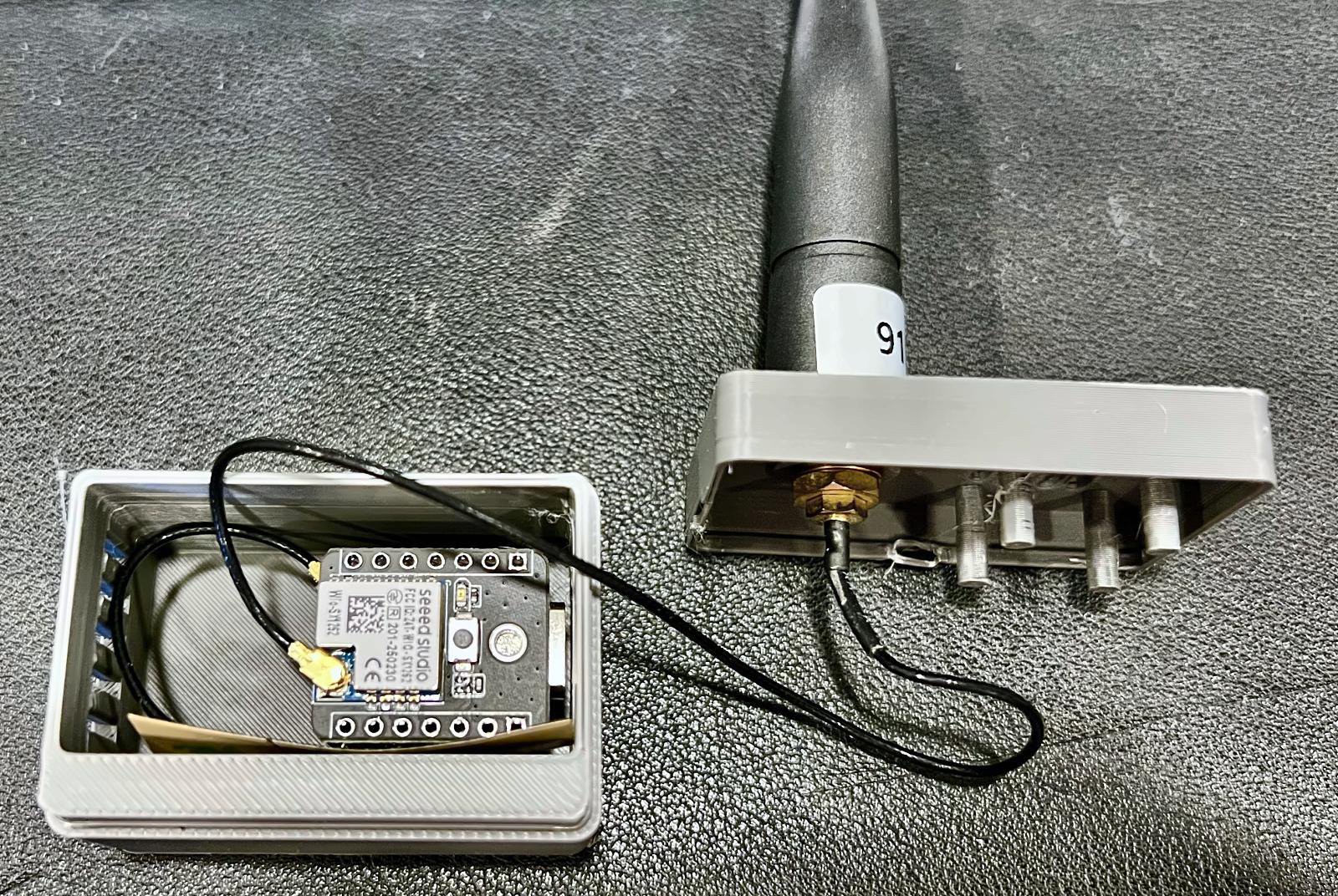
    The build A Seeed XIAO ESP32-S3 with a Wio-SX1262 on the board-to-board connector, running MicroPython v1.29.0 and powered by USB-C. A 2.4 GHz FPC antenna sits inside the front wall, and a 915 MHz whip mounts on an SMA bulkhead in the lid. The two-piece 3D-printed enclosure (about 47 × 32 × 30 mm, no supports) holds the board by pressing its pin headers into holes in the floor, with "LoRaLAN WiFi GW" engraved on the lid. A pin test coupon in the repo helps you dial in the hole fit first.

    How it's configured Wi-Fi, the broker, the gateway address and the topic prefix all go in one secrets.py. It publishes each packet to <prefix>/gateway<address>/rx, a retained status message every minute, and online/offline availability. If Wi-Fi or MQTT drops, it keeps ACKing and queues packets. To point a node at it, set SERVER_ADDRESS in the node's config.py to the gateway's address.

    Files Firmware, example settings, the MQTT format, and the enclosure STL, STEP and OpenSCAD source are all in the LoRaLAN WiFi Gateway repo. Earlier logs are on the LoRaLAN project page.

    Next Putting it to work and pointing nodes at it. I'm always looking for people to collaborate with. Want to try LoRaLAN on a farm, a large property or a remote site? I'd love to help get it set up.

  • Leak sensors deployed on LoRaLAN, all the way to Home Assistant

    Scott LeComte • 10/29/2026 at 20:11 • 0 comments

    The water leak sensors from the last log are now installed around the house, with several live and reporting into Home Assistant. They're the newest node type on LoRaLAN: like the gate sensor, temperature probe and weather station, they send RadioHead-style packets on 915 MHz to the Lora to Ethernet Bridge (address 2), which ACKs every packet and forwards it over Ethernet to Node-RED. Nothing changed on the bridge to add them. How all the nodes fit together is in the LoRaLAN repo, and the bridge build is written up on the blog in Local LoRa, no cloud required.

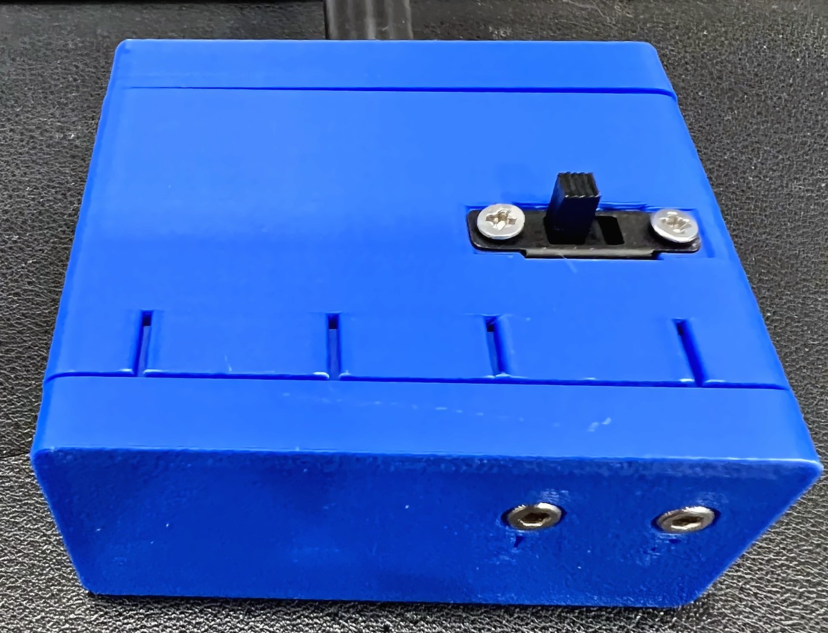
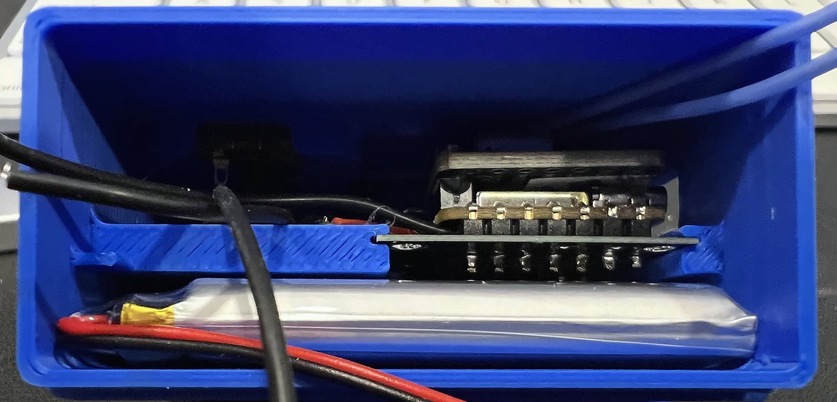
    The build Every node is a Seeed XIAO ESP32-S3 with a Wio-SX1262 on the PCB sponsored by PCBWay. The 0.66 mm boards slide into card guides in a three-piece 3D-printed PLA enclosure (base, body and lid, no supports needed), and the battery divider is two 1 MΩ resistors with a capacitor on the tap. 1 MΩ keeps the divider's constant draw low. An 1100 mAh LiPo powers it, with its leads soldered to the two battery pads on the underside of the XIAO and a mini slide switch recessed into the side of the case. The XIAO charges the cell, so charging is just plugging the sensor into USB-C. All of the nodes run MicroPython v1.29.0. Thanks again to PCBWay for the boards. They came back fast and clean, and they fit the enclosure perfectly.

    Parts list

    • 1 × Seeed Studio XIAO ESP32-S3: MicroPython v1.29.0 (ESP32_GENERIC_S3, SPIRAM_OCT build)
    • 1 × Seeed Wio-SX1262 for XIAO: On the XIAO's board-to-board connector (sold together as the XIAO ESP32-S3 + Wio-SX1262 kit)
    • 1 × Carrier PCB, 0.66 mm: Made by PCBWay. Holds the XIAO, the battery divider and the probe/battery pads
    • 2 × 1 MΩ resistor, 0603 (R1, R2): Battery divider, BAT+ to GND, tap on D2 (GPIO3)
    • 1 × 0.1 µF capacitor, SMD (C2): From the divider tap to GND
    • 1 × 1100 mAh LiPo, 50 × 29 × 7 mm: Leads soldered to the two battery pads on the underside of the XIAO. Charges by plugging the sensor into USB-C
    • 1 × SS12F15 mini slide switch (Amazon): Inline in the battery's negative lead (middle pin + one outer pin)
    • 2 × 2.2 × 6 mm self-tapping screw: Holds the switch ears to the enclosure
    • 2 × M2.5 × 8 mm socket-head cap screw: The probe bolts, through the base
    • 4 × M2.5 hex nut: Two per bolt: one captive in the base, one jam nut
    • 2 × Ring lug, M2.5: Probe wire to each bolt
    • 28 AWG silicone hookup wire: Probe leads and battery leads
    • 1 × Slinkdsco 915 MHz long range LoRa whip antenna (red, sold for Meshtastic, Amazon): Mounted on an SMA bulkhead in the lid
    • 1 × U.FL (IPEX) to SMA bulkhead pigtail: The Wio-SX1262 has a U.FL connector
    • 1 × 3D-printed enclosure, PLA: Three pieces: base (rev6c), body (rev6d), lid (rev6e). Prints without supports. Print settings on request

    How it's configured Every node runs the same firmware. The only per-node file is config.py, and only the address and MQTT topics change between nodes (the repo default is address 10 with water_sensor topics). The radio settings are shared across LoRaLAN: 915 MHz, BW125, SF7, CR4/5, with RadioHead-style addressing to the bridge at address 2 and an ACK on every packet.

    Sensing uses a fixed dry reference. A dry probe pins the ADC at 65,535, a reading of 64,535 or lower counts as wet, and it only returns to dry after two readings in a row at 65,200 or higher. When dry, it checks every 60 seconds, looks again after 15 seconds if a reading is close to the line, and checks every 15 seconds while wet. A heartbeat with the battery goes out every 6 hours, and a cold boot reports the real wet/dry state right away.

    Home Assistant Node-RED maps each node to a name, publishes to MQTT, and sends Home Assistant MQTT discovery. Each sensor shows up as a device with a binary leak sensor, battery % and mV, and RSSI/SNR. A leak sends a notification to both of our phones, and the dashboard has a tile per sensor plus a leak badge that only shows when something is wet. Every node passed a real wet test after install,...

    Read more »

  • Adding a battery-powered water leak sensor to LoRaLAN

    Scott LeComte • 10/22/2026 at 00:27 • 0 comments

    The next node on LoRaLAN is a water leak sensor. It's built to sit on the floor next to a water heater, washer, or anywhere else a slow leak can go unnoticed, and to run for months on a battery without ever touching Wi-Fi.

    **The hardware**
    Each sensor is a Seeed XIAO ESP32-S3 with a Wio-SX1262 LoRa radio on its board-to-board connector, running MicroPython. It's powered by an 1100 mAh LiPo. The probe is about as simple as it gets: two bolts through the bottom of the enclosure. One bolt goes to a GPIO with the internal pull-up and the other goes to ground. Water bridging the bolts pulls the reading down. A resistor divider on another ADC pin reports the battery voltage.

    The PCB that ties it all together was sponsored by [PCBWay](https://www.pcbway.com/). It's a thin 0.66 mm board holding the XIAO, the radio, and the battery divider, and the boards came back fast and clean.

    **How it behaves**
    The sensor spends almost all its time in deep sleep. Every 5 minutes it wakes, reads the probe, and goes straight back to sleep unless something changed. When it detects water, it sends a "triggered" packet to the bridge and waits for an ACK. Then it checks every 15 seconds until things dry out and sends "dry." Every 6 hours it sends a heartbeat with the battery voltage, so a quiet sensor isn't mistaken for a dead one. The radio only powers up when there's something to send.

    On first boot it learns its dry baseline and stores it in RTC memory, so every sensor calibrates itself to its own probe.

    **Tuning**
    Bench testing gave a clear picture of the readings:
    - Dry: 65,535 (fully pinned high)
    - Damp rag: about 6,700 below dry
    - Standing water: about 13,000 to 16,000 below dry

    The wet threshold is set at 2,000 below the baseline. That catches a damp surface while dry readings stay pinned, so there are no false alarms.

    **Battery**
    The node runs a 6-hour heartbeat in production, and most of its life is spent in deep sleep with a floor of a few hundred microamps. That works out to roughly 3 months or more on the 1100 mAh cell. Battery voltage is logged with every heartbeat, so a measured runtime will follow in a later log.

    **What's next**
    Nine of these are planned around the house, each with its own location in the config. A revised enclosure is in progress with an external slide switch for the battery, and the end-to-end path is already working: sensor to LoRa to the bridge, then into Node-RED, MQTT, and Home Assistant.

    Firmware and README: Local LoRa Moisture Sensor 

    https://github.com/scottlecomte/Local-LoRa-Moisture-Sensor

  • A small buffer bug found in testing new sensor

    Scott LeComte • 10/11/2026 at 16:18 • 0 comments

    I didn't find this bug by looking for it. I found it while bench-testing a new node: a XIAO ESP32-S3 moisture sensor with a Wio-SX1262 radio that reports its battery voltage in every heartbeat. I wanted to watch 'bat_mv' climb while the LiPo charged, so I kept resetting the sensor and watching Node-RED for each heartbeat.

    They took minutes to show up, and then several arrived at once.

    Following the packet

    The path is sensor → LoRa Pico (RFM95, 915 MHz) → UART at 230400 baud with A5 5A framing → Wiznet Pico → websocket → Node-RED → MQTT. With both the LoRa Pico and the Wiznet board plugged into the same machine, I logged their serial output side by side.

    The LoRa Pico was fine. It received each packet, sent the ACK, and handed the frame to the Wiznet within the same second. One packet left the LoRa Pico at 5:17:01 and reached Node-RED at 5:19:17. Two heartbeats from separate boots, 107 seconds apart, arrived at the same instant, and one burst had packet IDs 244, 245, 246 and 245 again. Obviously, that wasn't correct.

    First theory: packet size

    The sensor's early packets were chatty JSON, about 340 bytes at the bridge once base64'd and wrapped. The bridge has historically struggled with big frames, so I trimmed the payload down to the essentials (at most 95 bytes over the radio, about 210 at the bridge) and moved the location and topic mapping into Node-RED, keyed by node number (filtered in NodeRed by header_from = #)

    It didn't help. The smaller frames got stuck too.

    The numbers that gave it away

    The Wiznet's status heartbeat carries counters, and over one minute they told the whole story:

    • 'rxB' (bytes received) rose by exactly the size of the six frames the LoRa Pico sent.
    • 'frames' stayed frozen at 4971.
    • 'buf' (unparsed bytes) climbed 6787 → 7246 → 8162.
    • 'bad' and 'parse_err' didn't move, so nothing was being rejected.
    • 'sent_age' crept up to 95 seconds.

    So the bytes were arriving, and the parser just wasn't getting through them.

    Root cause

    About 8% of UART frames arrive damaged, most likely overruns while the Wiznet is busy on the network. When a damaged payload hit  _decode_payload, payload.decode('utf-8') threw a UnicodeError. The fallback, decode('utf-8', 'ignore'), doesn't help, because this MicroPython version ignores the errors argument and throws again. The exception was swallowed, the read position never moved, and every frame behind the bad one waited until the 8 KB buffer limit finally cut it off. Then the whole backlog went out in one burst.

    A quick simulation of the parser reproduced it: bursts of up to 35 frames with the old code, and every frame delivered immediately with the fix.

    The fix

    • _decode_payload returns None on a bad payload instead of clogging the buffer.
    • If the next frame's A5 5A header shows up inside the current frame's length, the current frame is garbled, so drop it immediately and resync at that header.
    • After any skip, the parse loop keeps draining instead of waiting for the next read.
    • Any other parse exception drops one byte and resyncs, and is counted in a new pexc field in the heartbeat.

    A damaged frame now costs one packet instead of stalling everything behind it.

    Result

    After flashing, the Wiznet heartbeat showed frames: 19, sent: 19, buf: 0, bad: 0, pexc: 0. A sensor packet ACKed at 7:36:16 was on the websocket before the 7:36:19 heartbeat. No more batching.

    And the battery test that started all this is now running for real. 

    Link to the fix

    https://github.com/scottlecomte/Lora-to-Ethernet-Bridge

    Moisture sensor project to be created soon!

View all 4 project logs

Enjoy this project?

Share

Discussions

Similar Projects

Does this project spark your interest?

Become a member to follow this project and never miss any updates