Close
0%
0%

Decent400

A drop-in replacement mechanical keyboard for the Atari 400's membrane, that respects the unique design of the computer

Public Chat
Similar projects worth following
0 followers
The 8-bit line of Atari computers, introduced in 1979, was incredibly ahead of its time. Designed by Jay Miner of future Amiga fame et al., the machine featured custom chips that enabled a 128 color palette, hardware scrolling, 4 channel audio, mid-screen changes of graphics mode and palette, sprites, DMA and a precursor to modern USB.

At about half the price of the Atari 800, the 400 was popular, but it came with a very poor excuse for a keyboard similar to the ZX-81's membrane.

Keyboard replacements were a common third-party upgrade, but because of the smaller footprint of the original, they had to use a modified and impractical layout.

The Decent400 keyboard is a modern replacement mechanical keyboard for the Atari 400 that preserves its looks and layout and requires no irreversible modification. It uses low-profile switches and custom UV printed caps that reproduce the relief outlines of the original. It also has backlighting and anti-ghosting diodes.

If you always wished the Atari 400 had a real keyboard, this is the project for you.

There's been a number of aftermarket keyboards for the Atari 400, but they all faced a big issue: the original membrane "keyboard"'s "keys" are much smaller than standard key caps. There just isn't enough space in the case for a sane layout with full-sized keys. It took a lot of attempts before coming up with the realization that there was an untapped degree of freedom in the design: the spacing of the keys. This is even more true of low-profile key caps, and given how infinitely taller MX switches and caps are compared to the original membrane thing, it made sense to try to build the Decent400 as a low-profile mechanical keyboard. I was finally able in late 2025 to fit the original layout of the computer in its very small space, with modern switches.

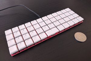
There was one final obstacle though, which is that as I'm writing this readme, no company in the world will print custom low-profile key caps. My only option was to somehow find a way to do it myself. When I heard about the Eufymake kickstarter for a UV printer capable of transferring a full-color design onto any material, it was clear it could be the last piece to the puzzle. It was a big investment, but I bet on it and waited and waited and waited. Finally, the printer arrived and check this out:

Side-by-side comparison with the vintage membrane

It even has the relief white outline on each key, a very satisfying detail...

The keyboard can be built with your choice of Kailh Choc v1 switches. I prefer the clicky Robins myself, but perfectly good tactile and linear options do exist if that's your preference.


SpaceBar-Choc-v1-6U25.3mf

3D model for the 6.25U low-profile space bar

3mf - 47.67 kB - 10/01/2026 at 22:20

Download

Decent400-emboss-block6.png

Portable Network Graphics (PNG) - 65.25 kB - 10/01/2026 at 22:19

Preview

Decent400-block1-1-9.svg

svg+xml - 39.54 kB - 10/01/2026 at 22:19

Preview

Decent400-emboss-block-1U.png

Portable Network Graphics (PNG) - 105.63 kB - 10/01/2026 at 22:19

Preview

Decent400-emboss-block7.png

Portable Network Graphics (PNG) - 13.36 kB - 10/01/2026 at 22:19

Preview

View all 10 files

  • 63 × Kailh Coc v1 switch
  • 1 × 6.25U low-profile stabilizer
  • 1 × 2U low-profile stabilizer
  • 57 × 1U blank black low-profile cap
  • 2 × 1.25U blank black low-profile cap

View all 16 components

  • 1
    Mount the switches onto the plate

    Insert switches into the plate with the LED window to the back and the pins to the front.

  • 2
    Mount the stabilizers

    The stabilizers consist of two parts and a rod. They must first be assembled and then added to the plate from the underside.

    Thereś plenty of tutorials that get into the details of installing those stabilizers. Here's one:

    Kailh Chox stabilizer installation

  • 3
    Get the plate and PCB together

    After making sure all the switch pins are vertical and none are bent out of place, carefully align the plate and switches with the PCB. Slowly and carefully complete that assembly, making sure no pins get bent. Once that is done, the plate and PCB should be a few millimeters apart, evenly spaced across the whole surface.

    You may secure the boards together with tape or clothespins until you've soldered enough switches.

View all 11 instructions

Enjoy this project?

Share

Discussions

Similar Projects

Does this project spark your interest?

Become a member to follow this project and never miss any updates