Close
0%
0%

Making a 1971 computer do CT scan reconstruction

My journey from acquiring a bare Data General Nova computer to it doing CT scan reconstruction as in the first medical CT scanner

Similar projects worth following
121 views
0 followers
The first CT scanner was designed around 1970 by Geoffrey Hounsfield, earning him the Nobel Prize. CT (Computer Tomography) means cutting the human body into virtual slices, and provided, for the first time, an unobscured view inside. The first scanner was brain only and allowed diagnosis of e.g. brain tumours. Reconstruction has to be done by a fairly powerful computer.

The first commercial CT scanner used a Data General Nova 820 computer, from the first family of 16 bits minicomputers. I acquired a slower Data General Nova 1210 from 1971 and this project shows my journey from a bare metal CPU to a full demonstration of CT reconstruction, both on the actual machine and on a simulator using a Raspberry Pi Pico with an LCD display.

If you want a piece of the action, files to build your own Nova simulator including the image reconstruction are included.

Full source code, board designs and emulator are on Github: https://github.com/marcelvanherk/nova1200-restoration

I bid 250 pound for a "Data General Nova 1200" computer on Ebay in the UK and won the auction on 28 April 2017.  The photo shows my first (but not last!) dissassembly of this system, released in 1971.
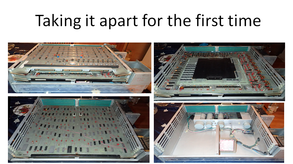
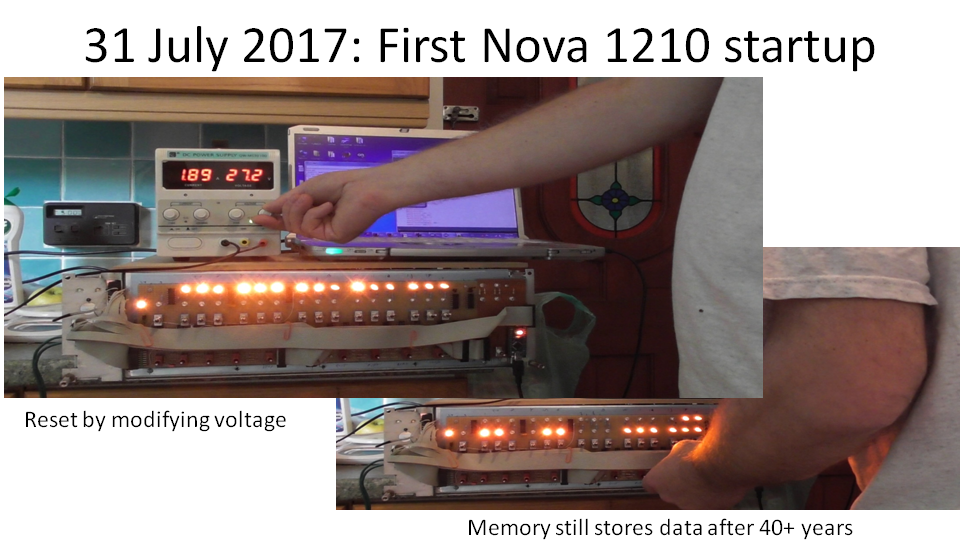
This computer came from a Singer Photomix 8400, a phototypesetter (grandfather of a laser printer). The top board in the photo (top-left) above is the interface board. Then (top-right) we have the 8kx16 bits magnetic core memory board, bottom-left the CPU board (TTL logic) and botton-right the power supply. Because this Nova has been embedded it did not require any control switches. I.e. the so-called frontpanel was missing. Time to build my own.On this first frontpanel, the banks of lights (orange LEDs, for similar color as old-fashioned bulbs on the Nova) represent address and data in binary. My Nova (manufactured in 1973 as seen from the IC datestamps) must have been off for 40 years or so, but the original data and code were still in the core memory. The Nova seemed completely functional! The hand-wired frontpanel started to fail quickly though.
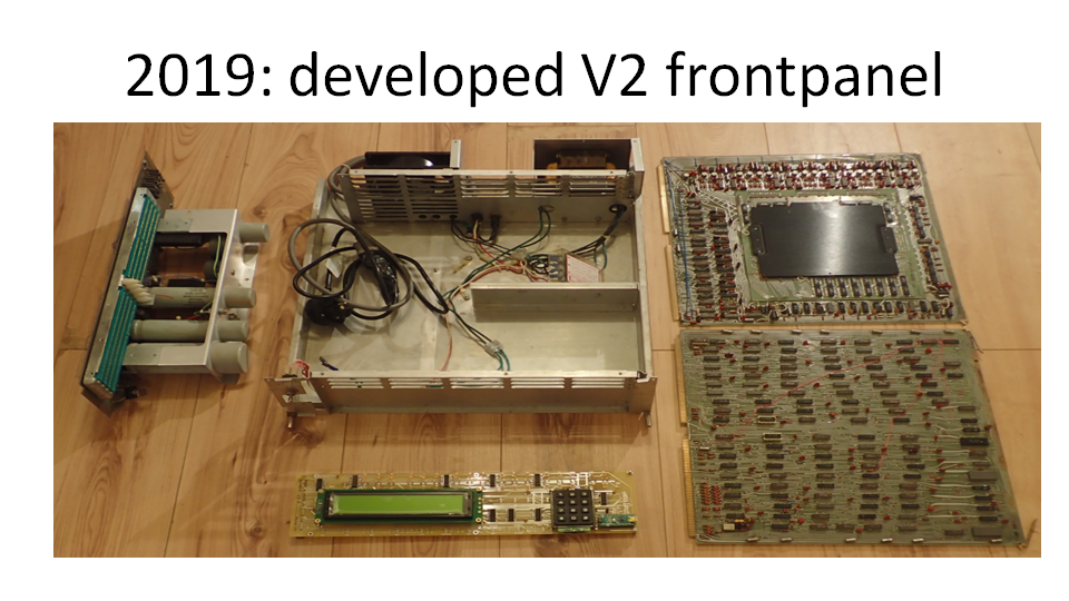
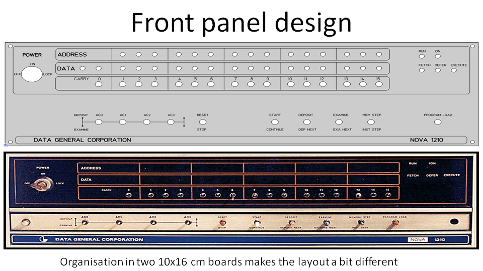
The project slept for a while until I was forced to stay at home early 2019 due to a health issue. I knew that my favorite conference (ICCR = International Conference on the use of Computer in Radiotherapy) was upcoming. Why not submit a paper about this computer doing CT reconstruction? I decided to make a more user-friendly frontpanel using a manufactured PCB (picture below). 

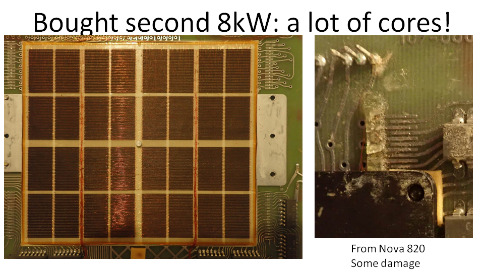
The original CT scanner made images with 80x80 pixels that would fill up 6400 words, using most of my 8k core memory. Time to buy more. I found a slightly damaged board on Ebay from the US for $95. With shipment to the UK and tax the price doubled. On inspection, some of the hair-thin wires has broken and had to be repaired. Also the timing of the board needed to be adjusted. As the Arduino was running out of space, I replace it by a Teensy. In the larger storage space of the Teensy, a user-friendly monitor software was written. I wrote a small cross-assembler in Lua that allows modifying the assember code on the PC, upload it and instantly run it on the Nova. I did run out of time before my ICCR talk, so CT reconstruction was not complete. The talk is here: ICCR 2019 talk Marcel van Herk
Later I also wrote a Nova simulator into a V3 frontpanel that I had designed. Time for a Battle of the Nova's. 

In 2024 I was invited to the give the annual British Society for the History of Radiology (BSHR) lecture, and I decided to take up the challenge again. One of the issues was the lack of a proper display. How to perform output to a display from a 50+ years old computer? It turns out that the HALT instruction in the Nova has 4 unused bits. This means one can use 15 HALT-equivalent instructions to do things in the Teensy or Pico such as GRMODE and GRDISPLAY to display data on the graphics display, and READBLOCK and WRITEBLOCK to read and write data to EEPROM or SD card.Input data for CT reconstruction is an array of measurements with X-Ray detectors as the scanner rotated around the patient, called a sinogram. There is not enough space in the Nova's core memory for the sinogram and a reconstructed CT slice (the EMI scanner had a disk drive). I therefore load the input data from the (large) code memory of the Teensy. The finished optimised reconstruction code runs below in 23 s NOVA time (a lot faster than in the original CT scanner!).
The full lecture can be seen here: BSHR lecture 2025
teensy_nova.ino.rpipico2.uf2

Take one Raspberry PICO2, one waveshare Pico-ResTouch-LCD-3.5, one Adafruit Seesaw encoder, half a QWIC cable and SD card. Solder blue to GP4, yellow to GP5, black to GND and red to 3V3. Flash the attached UF2 file. Power ON. Connect a serial terminal. Say enter, session bshr, store. Voila, a working Data General Nova CT reconstruction demo system. Push the encoder for the menu and have fun.

uf2 - 1.07 MB - 10/07/2026 at 20:04

Download

  • 1 × Raspberry PICO2 With headers
  • 1 × Waveshare Pico-Restouch-LCD-3.5 480 x 320 tft display with PICO and SD card slot (touch not used)
  • 1 × SD card FAT formatted, any size
  • 1 × Adafruit I2C Stemma QT Rotary Encoder Breakout with NeoPixel - STEMMA QT / Qwiic Used as push/rotate/push user interface
  • 1 × 20cm STEMMA QT / Qwiic cable Cut in half, solder blue to GP4, yellow to GP5, black to GND and red to 3V3.

  • Detailed log of the journey taken

    marcelvanherk • 2 days ago • 0 comments

    2017 

    I bid 250 pound for a "Data General Nova 1200" computer on Ebay in the UK and won the auction on 28 April 2017.  It arrived on 10th of May and because I do not have a car, I called a taxi to bring the heavy box home from the post office. The first photo shows the NOVA computer dissassembled.

    This computer came from a Singer Photomix 8400, a phototypesetter (grandfather of a laser printer). It contains 4 board, the top board in the photo above is the Singer interface board. Then on the right we have the 8kx16 bits magnetic core memory board, lower left the CPU board (built out of simple TTL logic) and finally the power supply. Because this Nova has been embedded it did not require any control switches. I.e. the so-called frontpanel was missing. Time to design and build my own!

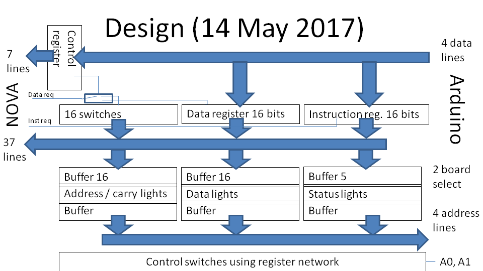
    Based on the Nova documentation on BitSavers I designed a circuit with an Arduino Nano that could very quickly toggle all the switches shown above. The switches have functions such as "Examine" an address given in binary by the bank of switches in the middle. "Deposit" writes the switches state to memory. Other switches run a program, read or write on of the Nova's registers, etc. Note that the switches are grouped in banks of 3, as in those days octal (not hex) notation was used for binary data. The Nova bootloader code was typically toggled in with these switches. Because core memory is non-volatile, this did not have to be done often.The obvious advantage of a computer-controlled front panel is that it omits the tedious toggling to load a program. This can instead be done from a PC connected to the Arduino.My V1 frontpanel was hand-wired. It took more than two months and a bit of debugging hardwire and writing some Arduino code before I first dared to startup the Nova. The Arduino reads the key states and communicates with the Nova writing using 10 4-bits three-state 74LS173 latched, and reads the bus data (shown on the LEDs) using 5 tri-state 74LS253 2x4 multiplexers. I used 9 74LS07 6-non inverting buffers to drive the LEDs. The lower bank of switches connects an resistor network such that the Arduino can see which switch is toggled by reading an analog voltage. The banks of lights (orange LEDs, to get a similar color as old-fashioned bulbs on the Nova) represent address and data in binary. This Nova (manufactored in 1973 as seen from the IC datestamps) must have been switched for 40 years or so, but the original data and code was still in the core memory. The Nova seemed completely functional! Next I added a small dissassembler and connected an LCD display and small keyboard to the Arduino, but programming it remained difficult. Even worse was that I used cheap toggle switches on the V1 frontpanel that started to fail. 

    2019

    The project slept for a while until I was forced to stay at home early 2019 due to a health issue. I knew that my favorite conference (ICCR = International Conference on the use of Computer in Radiotherapy) was upcoming. Why not submit a paper about this computer doing CT reconstruction? But this would required a more user-friendly setup. I decide to make a more user-friendly (but less historically accurate) frontpanel using a manufactured PCB.

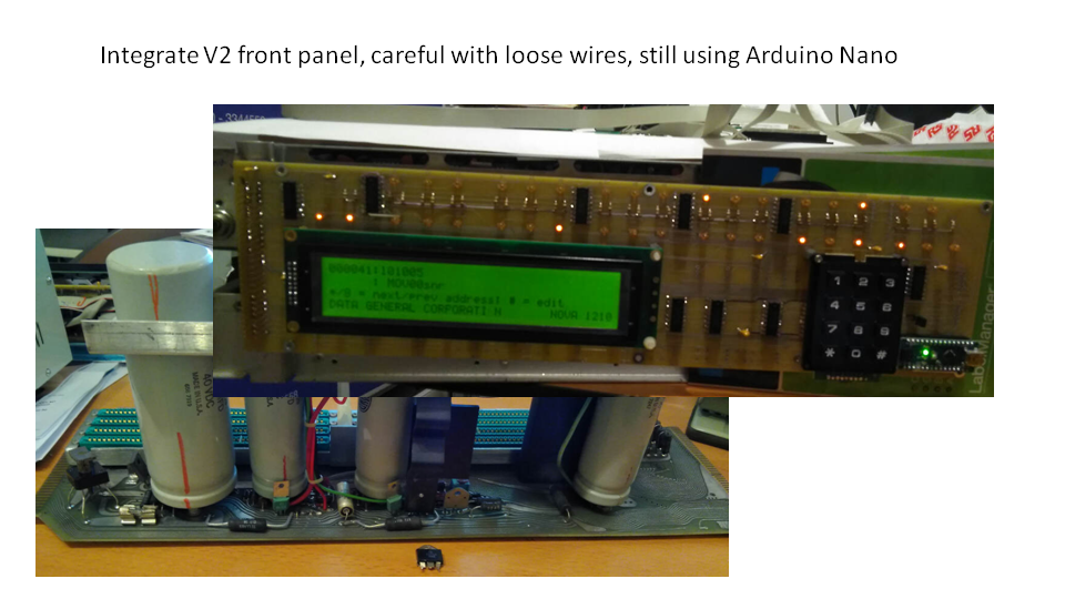
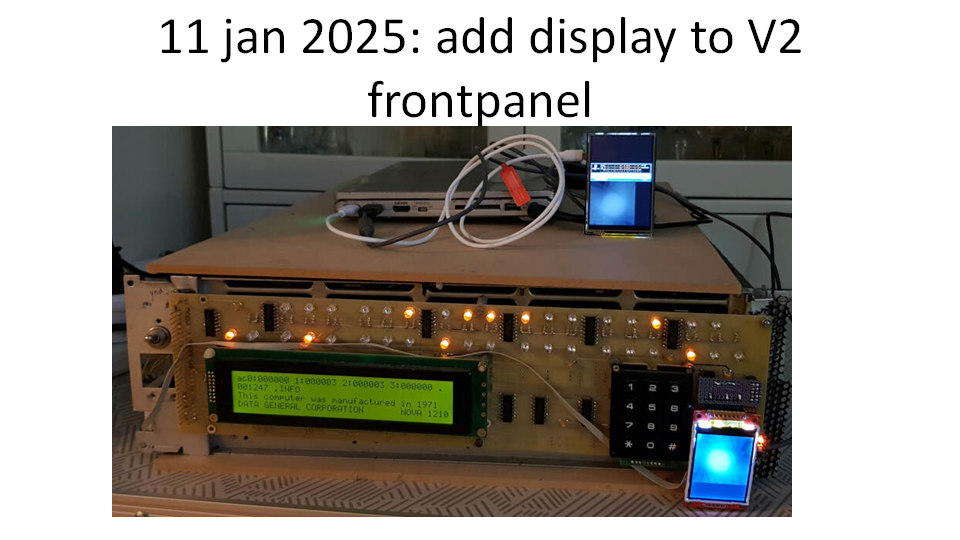
    This V2 frontpanel has a large LCD display and a small keypad instead of the banks of switches but is otherwise identical to the hand-wired V1 frontpanel. 

    The photo above shows it working. But I did blow up the Nova power supply in the process and had to replace its fuse, rectifier and driver transistor. 

    The original CT scanner made images with 80x80 pixels that would fill up 6400 words, most of my 8k core memory. Time to buy more. I found a slightly damaged board on Ebay from the US for $95. With shipment to the UK and tax the price doubled. On inspection, some of the hair-thin wires has broken.But at first, the entire board did not work at all. It turned out this RAM board was from a faster Nova820 computer (800ns cycle time). Using...

    Read more »

View project log

  • 1
    Build simulator with minimal soldering

    Take one Raspberry PICO2 with headers, one Waveshare Pico-ResTouch-LCD-3.5, one Adafruit Seesaw encoder, half a QWIC cable and an SD card. 

    Solder the half QWIC cable to the Pico-ResTouch-LCD-3.5:  blue to GP4, yellow to GP5, black to GND and red to 3V3. 

    Flash the attached UF2 file. Power ON. Connect a serial terminal. 

    Say enter to turn the NOVA on, "session bshr" to load the CT demo and "store" to make the system start into demo. 

    Voila, a working Data General Nova CT reconstruction demo system. Push the encoder for the menu and have fun.

  • 2
    Use of the emulator to run 1969 DG-Basic

    Connect a serial terminal.

    enter turns the Nova on.

    "tape .basic", enter-enter runs the 1969 basic. Type Y and then Escape to start it.

    ctrl-c bring you back to the monitor.

  • 3
    Use of the emulator to run 1969 DG-Basic with some code

    Connect a serial terminal.

    enter turns the Nova on.

    "session .basicsample", enter-enter runs the 1969 basic with s short program. Type Escape and then "RUN" to start it. Escape to stop, "LIST" to list the code etc. The Basic manual in the Github repository.

    ctrl-c bring you back to the monitor.

View all 3 instructions

Enjoy this project?

Share

Discussions

Does this project spark your interest?

Become a member to follow this project and never miss any updates