• Ordered new PCBs

    itzandroidtab • an hour ago • 0 comments

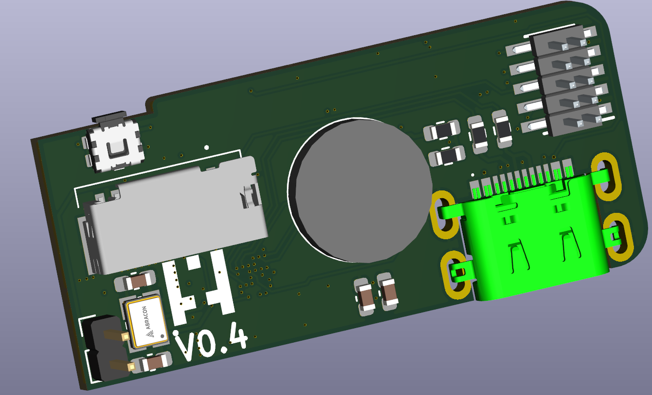
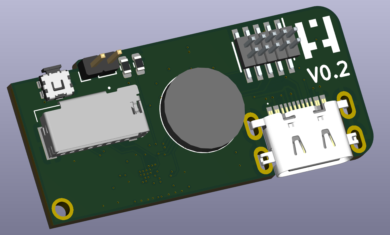
    When I was updating the PCB I also fixed one more issue that I found during testing. For some reason I was not able to reduce the power draw of the ATSAM4S2BB to a level I would like it to be so I changed back to the same mechanism as the previous version where the hardware button controls the enable line of the power regulator and the microcontroller takes over when it turns on.

    I also found another issue but I decided that was oke for now. It looks like the charger IC I dediced on cannot handle the current draw from the SD-Card when it does a write without a battery. Maybe Ill update this in the future but for now doing nothing on it.

    The PCB house I was using changed their prices quite a bit. Went from 50 euro to 70 euro for 5 boards even when I went from 8 layers (because I was lazy) to 6 layers, so decided to try the panneling service for once. For some reason it still costs the same but will get 50 bords now instead of 5. Will see how it goes.

  • Back to the Dev board

    itzandroidtab • 2 hours ago • 0 comments

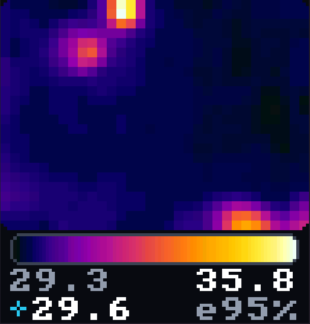
    So after that half failed PCB I went back to the dev board and started adding some extra features the previous version didnt have for showing the picture. The previous version I made just scacled each pixel to 3x3 on the screen. That way the 32x24 pixel from the camera showed up as a blocky 96x72 image.

    So first I added an average filter, then a denoise and then last a smooth upscale. This added quite a big improvement in how it looked on the screen.

    The original look of the previous version (upscale block mode)
    A new smooth upscale
    Denoising
    Averaging

    In the end it looks quite good even with only a 32x24 sensor.

  • PCB arrived

    itzandroidtab • 2 hours ago • 0 comments

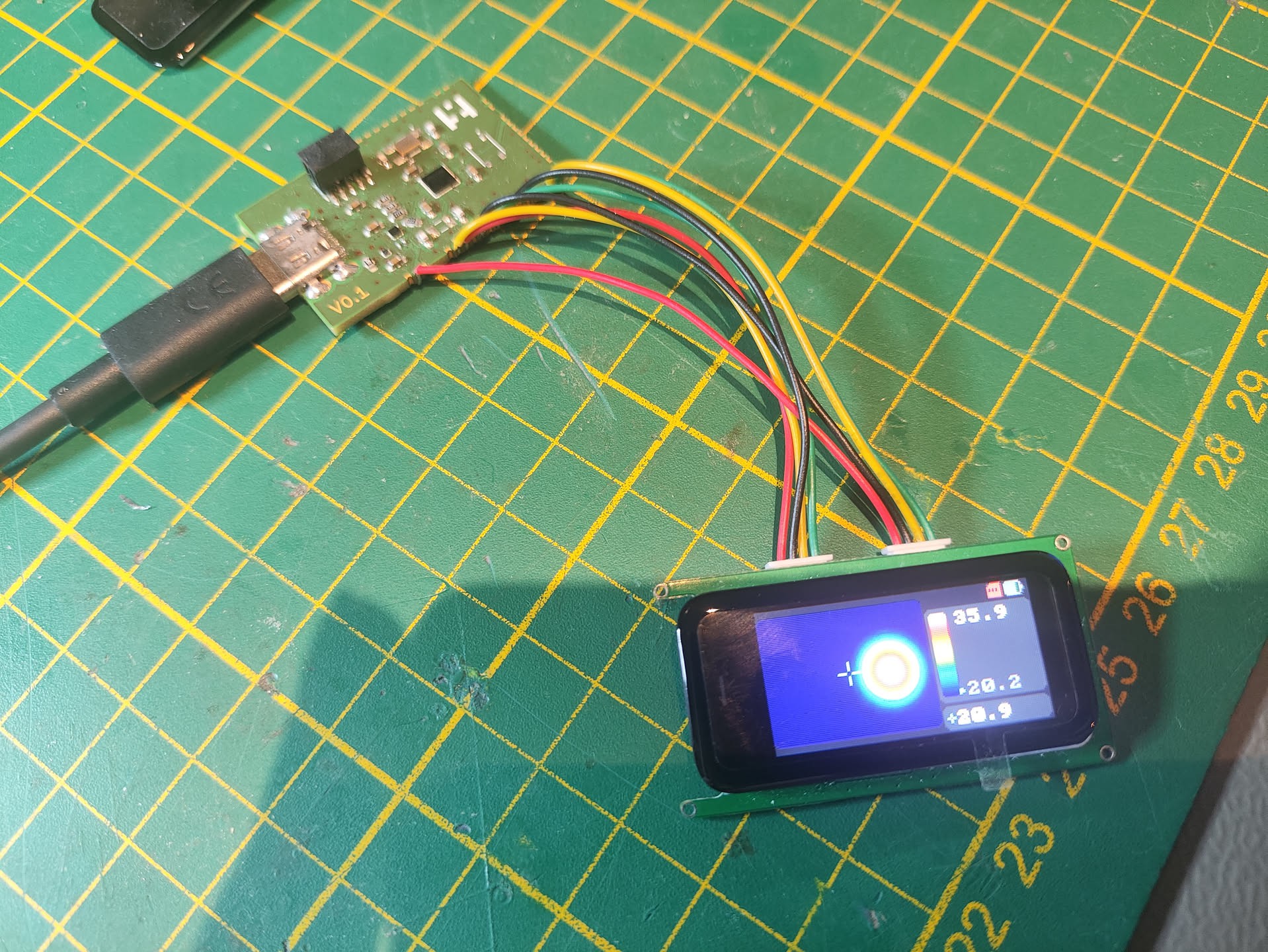
    While I was testing the software a package with the MLX90642 and the PCBs arrived. I quickly populated all the parts and started programming the same software I made for my dev board to the unit. Microcontroller was starting up, USB connection was recognized by my PC and nothing happened on the screen.

    So I started debugging the connections and everything looked fine. After some headbanging I finally figured out the issue. The Aliexpress seller had the pin numbering mirrored. So 1 2 3 4 5 6 became 6 5 4 3 2 1 and I flipped the connections. I thought I double checked this on the board with the display but I forgot that the Aliexpress board has the cables folded over. So there goes the display and touchscreen support.

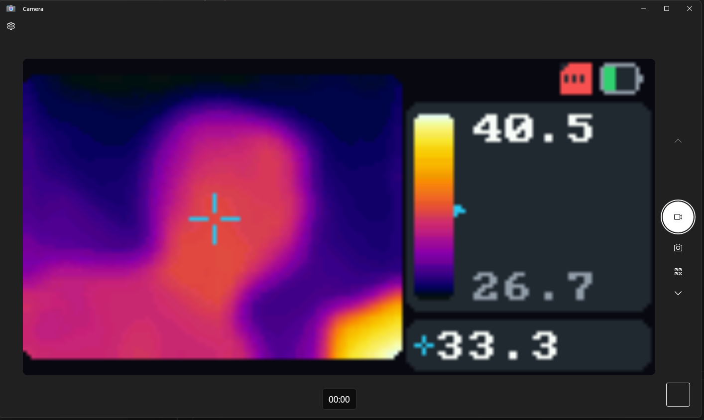
    While I couldnt use the screen I was able to test some of the other features like the USB webcam support.

    And I was able to test the SD card support. It writes both a BMP and a RAW file with the temperatures to the disk. That way I can decode the actual temperature later down the road.

  • SW development

    itzandroidtab • 2 hours ago • 0 comments

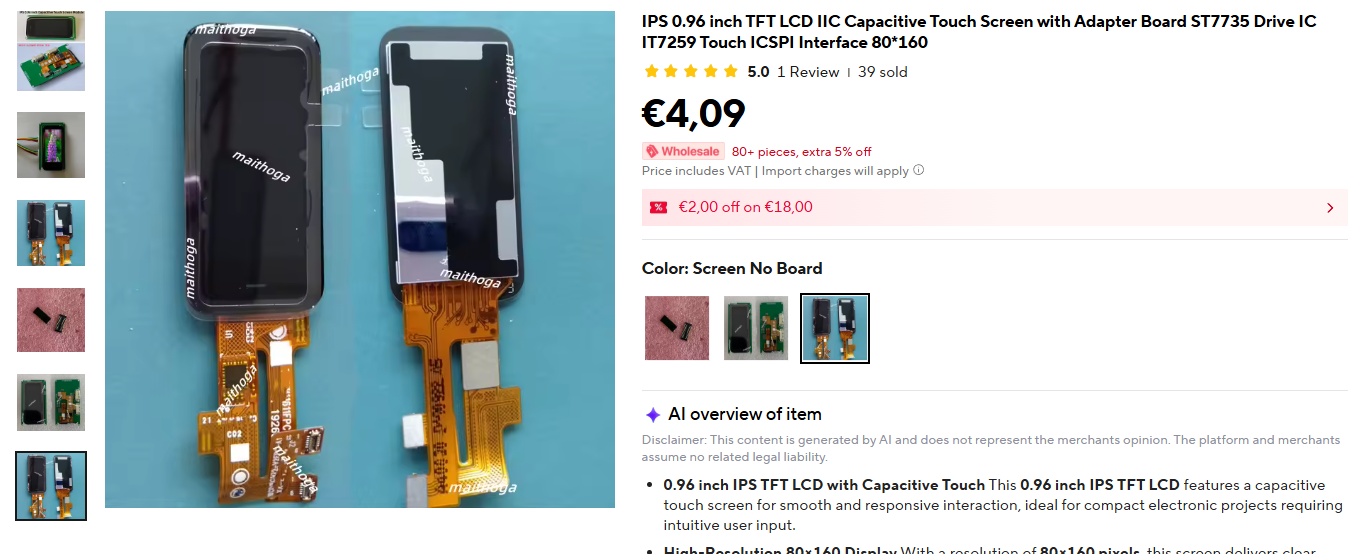
    While I was waiting on the ordered PCBs I did some development on the screen I had chosen. I found this floating around on aliexpress and it looked like a perfect fit for my camera. It was small and it had the same display controller (and resolution) as the previous temperature camera but it had a touchscreen. It looks like it is from some kind of smart watch.

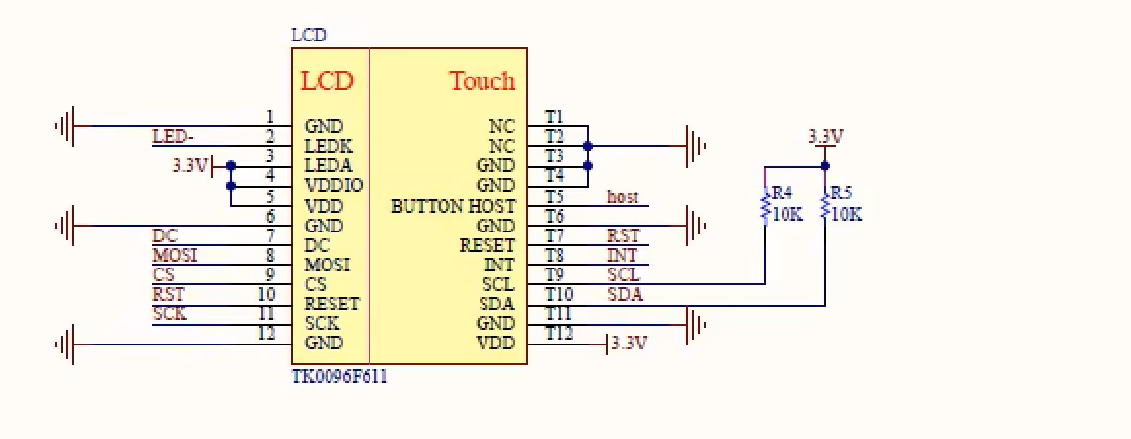
    I found it randomly scrolling but I you search for "ST7735 Drive IC IT7259 Touch" you can find it there. Before I started this project I already ordered some with no board and one with a PCB they made. Seller was pretty helpfull and gave me the schematic they made and I used that in the PCB design.

    So I got to work and programmed something a ATSAM4S2BB-UUR dev board I made before. On the dev board I didnt connect the MLX90642 yet as it was still in the mail.

  • PCB design

    itzandroidtab • 2 hours ago • 0 comments

    So with all these things in mind I spun up KiCad and made a schematic with the ATSAM4S2BB-UUR and some more stuff I had laying around.

    When I was creating the PCB I also wanted to try some of the low power stuff the microcontroller had so I decided to make the microcontroller permenently connected to the the power rail (coming back to this later). 

  • USB and JTAG

    itzandroidtab • 2 hours ago • 0 comments

    On my previous version I wanted to make the board as small as possible. When I had everything together I noticed it was a pain in the ass to charge it so I added a external Micro-USB connector that I handwired to the board. This made it at least easy to charge.

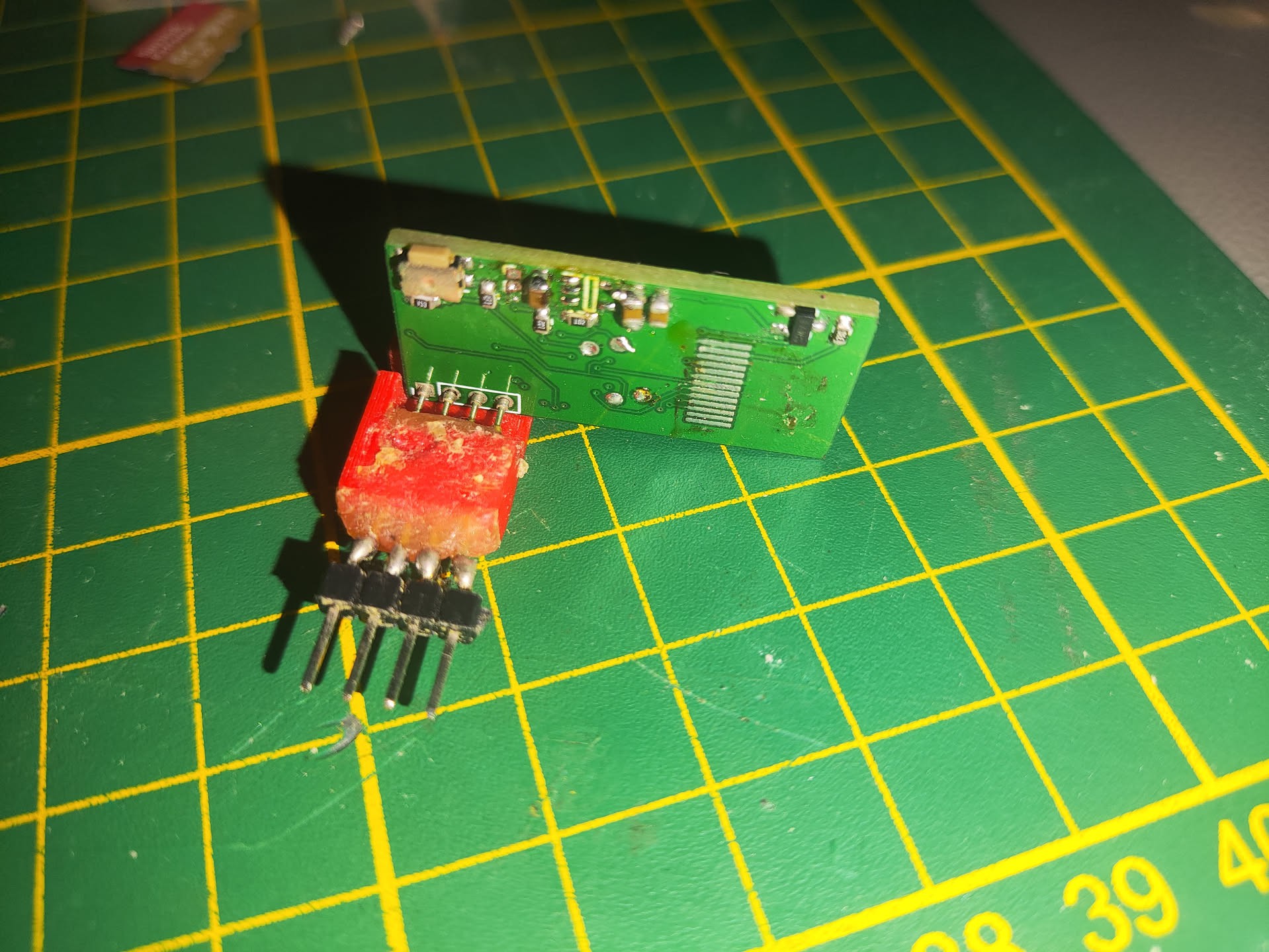
    For SWD it as a different thing. When I made the board I decided a 4 pin 1.27mm header is pretty small lets add that. I made a JIG with pogo pins that connected to those pins and I connected that to my debugger. That worked great until after I removed it and had to attach it again if I found a bug.

    To fix this I wanted a JTAG/SWD port with a dedicated header I could solder on and connect to with a standard 9-Pin MIPI ARM connector. For the USB I wanted to use a USB-C connector as that is what I have laying around most nowadays.

  • New project

    itzandroidtab • 2 hours ago • 0 comments

    After using my previous temperature camera for a while I noticed some additional features I would like to have on the camera. The main upgrade I wanted was to be able to connect it to my PC and use it as a webcam. That way I didnt have to play with SD-Cards to get images from the camera.

    In my quest to add USB I went through my box of microcontrollers that had hardware USB support. I did find a few that had USB and a floating point unit but they were way to big to fit on a small camera. Luckly, I found out that Melexis released a new MLX90642. This sensor is almost the same as the MLX90640 but it does all the temperature calculation onboard. With this new sensor I picked on of the smallest microcontrollers I have with USB the ATSAM4S2BB-UUR. I got quite a bit of these back in the day when they were on clearance on Arrow.