 Andrew Tudoroi

One day in a charity shop, I spotted a beautiful Aristona CD player. As an engineer, I have always been fascinated by the different ways we store information: magnetic tape, grooves in vinyl, and optical discs. I have a soft spot for physical media, which brings back memories of growing up with cassettes and CDs.
That first find got me hooked. I picked up another player, and then another. I now have a Philips CD480, an Aristona 1371, and an Akai CD player. They sound lovely, and I enjoy using them without pretending to be a serious audiophile. If a piece of equipment makes me happy when I listen to music, that is enough for me.
I also enjoy reading the service manuals for these machines. They are unusually complete, with schematics, explanations of how the circuits work, and clear troubleshooting procedures. The boards are spacious and mostly built from through-hole components, making them easier to inspect and modify. It is impressive that such complex, mass-produced equipment can still be working decades later.

The Display Problem
The CD480's original LED display is one of the weak points I kept hearing about from other owners. It can fail, and replacements are not easy to find.
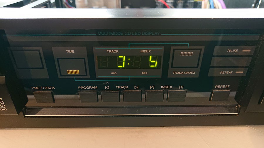
I found an existing replacement approach, but I wanted to try a different one. My goal was to make a board that fits the original display area, brings the modules closer together, and uses a modern driver. I also wanted to keep the door open for experimenting with custom display patterns later.
The basic idea is:
CD480 MM5450 serial data -> microcontroller translator -> I2C LED drivers -> LTP-305 matrix displays
Choosing the Displays
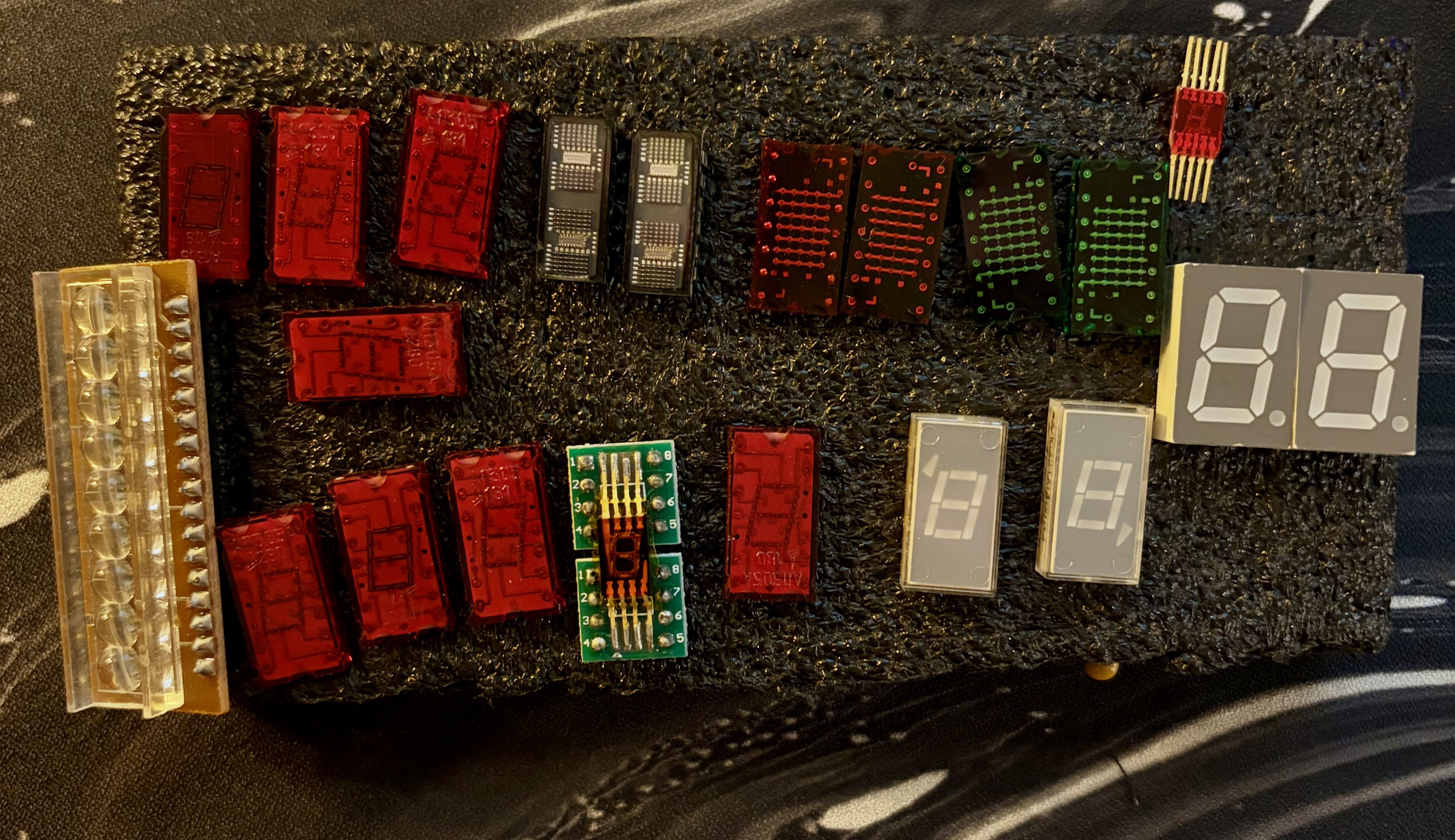
I started by looking through my parts box. I found a few DSP2913 and HSP200 modules, but they were a little too small for the space available. The LTP-305G and LTP-305R 5x7 LED matrix modules looked like a much better fit, and I already had some on hand.
The matrix displays give me more flexibility than a fixed 7-segment digit. The same general idea could also be adapted to other display modules, but this version is designed around the LTP-305 footprint.
Designing the Replacement Board
There is already another replacement solution for these displays. For purists, it is probably the preferable approach because it sticks with the same LED controller as the original display board.
In my opinion, the display used in the first version does not look quite right. There is an improved version, but I am not sure whether it is open source; at least, I was unable to find the project files.
Reusing the original controller would still be a bit of a gamble for me. I sourced some supposedly "new" MM5450 LED drivers from a well-known marketplace. Sure enough, the one I soldered in, despite my efforts not to stress it too much, does not seem to be fully functional. It shows signs of at least two defective or shorted segments.
That has also been my experience with quite a lot of "new old stock." The odds may not be exactly 50/50, but there is still a very good chance of receiving rejected, counterfeit, or partly defective ICs.
For that reason, I focused on making a solution based on modern LED drivers. I also wanted it to be flexible, so I could later replace the 5x7 matrix displays with 7-segment displays in the same physical space and keep the same character alignment.
I measured the original display assembly and used those measurements to position the new displays so they line up with the front panel. Then I laid out the replacement board in KiCad.
For the LED drivers, I chose the IS31FL3730. i have used them before and fiind them quite intersting and versitile led drivers both for CA CC aplications.
Schematic: schematic.pdf
The board uses two of these I2C matrix drivers, at addresses 0x60 and 0x61 to control four LTP-305G displays. Each driver handles a pair of displays. Their compact QFN packages helped me fit the electronics into the available space between...
Read more »