Close
0%
0%

Arduino Neopixel Watch

Neopixel watch with accelerometer.

Similar projects worth following
An Arduino compatible easily programmable Neopixel watch with Accelerometer control and minimalistic outer design.

with battery life, waterproofing, fitness tracking, and completeness being the main goals for this watch that is unique compared to other DIY neopixel watches.

Using neopixels to be able to change the color and brightness of each marker  we can solve most of these problems; as well as using an accelerometer to keep water out of the case, as well as a light sensor to adjust brightness.

With 12 markers the watch can tell time with a accuracy of an average of 2.5 minutes.

Using the accelerometer to activate the neopixels with the flick of the wrist or a double tap (similar to action seen in smartwatches) the neopixels are turned on with a sweeping animation. Additionally a constant neopixel at a light level of 1 will turn on at the 12 o'clock possession to be able to see the relative location of the others in the dark.

Most other neopixel watches have very low battery life, This one addresses that problem by full disconnecting the neopixels from power to avoid powering the microcontrollers within each neopixel that can consume 2.5mAh each even when the neopixels are off.

power calculations for watch.xlsx

sheet - 12.11 kB - 03/30/2017 at 13:01

Download

gantt chart (2).xlsx

time line of the main production stage of the project

sheet - 13.61 kB - 03/30/2017 at 13:00

Download

watch board assembly.SLDASM

watch assembly

sldasm - 439.03 kB - 03/30/2017 at 12:59

Download

watch programming and charging adapter.SLDPRT

clip for charging and programing

sldprt - 129.67 kB - 03/28/2017 at 18:11

Download

watch with lip for 37mm board.SLDPRT

watch case file

sldprt - 830.02 kB - 03/28/2017 at 18:11

Download

View all 8 files

  • 1 × Watch Case Might be able to find some cheap watches online that are drop in.
  • 1 × Atmega328p Microprocessors, Microcontrollers, DSPs / ARM, RISC-Based Microcontrollers
  • 1 × Accelerometer ADXL345 Desoldered from a brake out board
  • 1 × Real Time Clock DS1308
  • 12 × Neopixel LEDs WS2813 with built in capacitors

View all 19 components

  • Adding bluetooth!

    Marcello Graves05/15/2017 at 15:39 0 comments

    After reaching out to others who have made similar neopixels watches asking if they would like to help inorder to be able to, add additional functionality, such as bluetooth and app support. With additional team members working on different aspects of the watch.

    Austin Nelson - App developer

    Leon Gaulin - Arduino programmer

    and others.

    Blue tooth adds a nice GUI as opossed to different tap detection modes, as well as Notifications and tactile feed back for alerts.

    Demo of bluetooth app found here https://hackaday.io/project/20693-flora-ble-smartwatch

  • Circuit board problems

    Marcello Graves05/08/2017 at 14:36 0 comments

    After reflowing the board, after some testing it dose not connect to the computer, I think it is due to cooling it down to quickly as I recall hearing some cracking noises when it was cooling down. believing this was the problem I soldered up another board, taking care not to let it cool down to quickly.

    As i go and hook it up to the computer realizing I let my friend barrow my programmer over the week end I try to use a cheap one i had laying around but upon testing the programmer on a known to work arduino pro mini the programmer dose not not work. So I ordered a new one, came in a few days later. I hook up the new board and it dose not work!

    So I test the neopixles by hooking up some test pins to the signal in on the neopixles from another arduino, they work fine.

    hook up a arduino to the i2c line and it dose not work, could possible be the light sensor because it is square and the pin 1 marking is really hard to see so I could have gotten it backwords, going to desolder it and test the I2c lines again.

  • Circuit board arrives

    Marcello Graves04/25/2017 at 14:30 0 comments

    After several weeks of waiting the boards come in just as I finish up the case a day before. The stencil was cut on a laser cutter but the settings were off and I didn't have time to make new ones so the stencil only was able to apply solder paste to the bigger pads so I added solder to the smaller capacitors and resistors with a needle.

  • Watch case

    Marcello Graves04/19/2017 at 18:42 0 comments

    Watch case fresh out of the mill, ready to be broken out of the extra bits holding it onto the stock. After inspecting the inside it seems to be perfect fit for the battery, will be able to do a test fit of the circuit boards ones they come in.

  • Charging connector continued

    Marcello Graves04/05/2017 at 17:33 0 comments

    The charging connector also acts as a programming cable for the Atmega328p. To save on space the battery charging circuit is externalized, using the pogo pins and concave pins on the back of the watch, has all the nessesary pins to be able to charge and reprogram the Atmega. Using a standard battery charger and a FTDI brake out connected to the pogo pins.

  • Charging connector

    Marcello Graves04/03/2017 at 16:57 0 comments

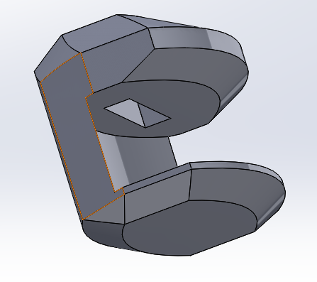
    The charging connector has a major flaw, due to the pins sticking out, that make it difficult to slide onto the case of the watch with out possibly damaging the pins. In order to solve this we added a angle up to the pins to lead the watch into the clip.

  • 2017: A New Beginning

    Marcello Graves03/30/2017 at 16:45 0 comments

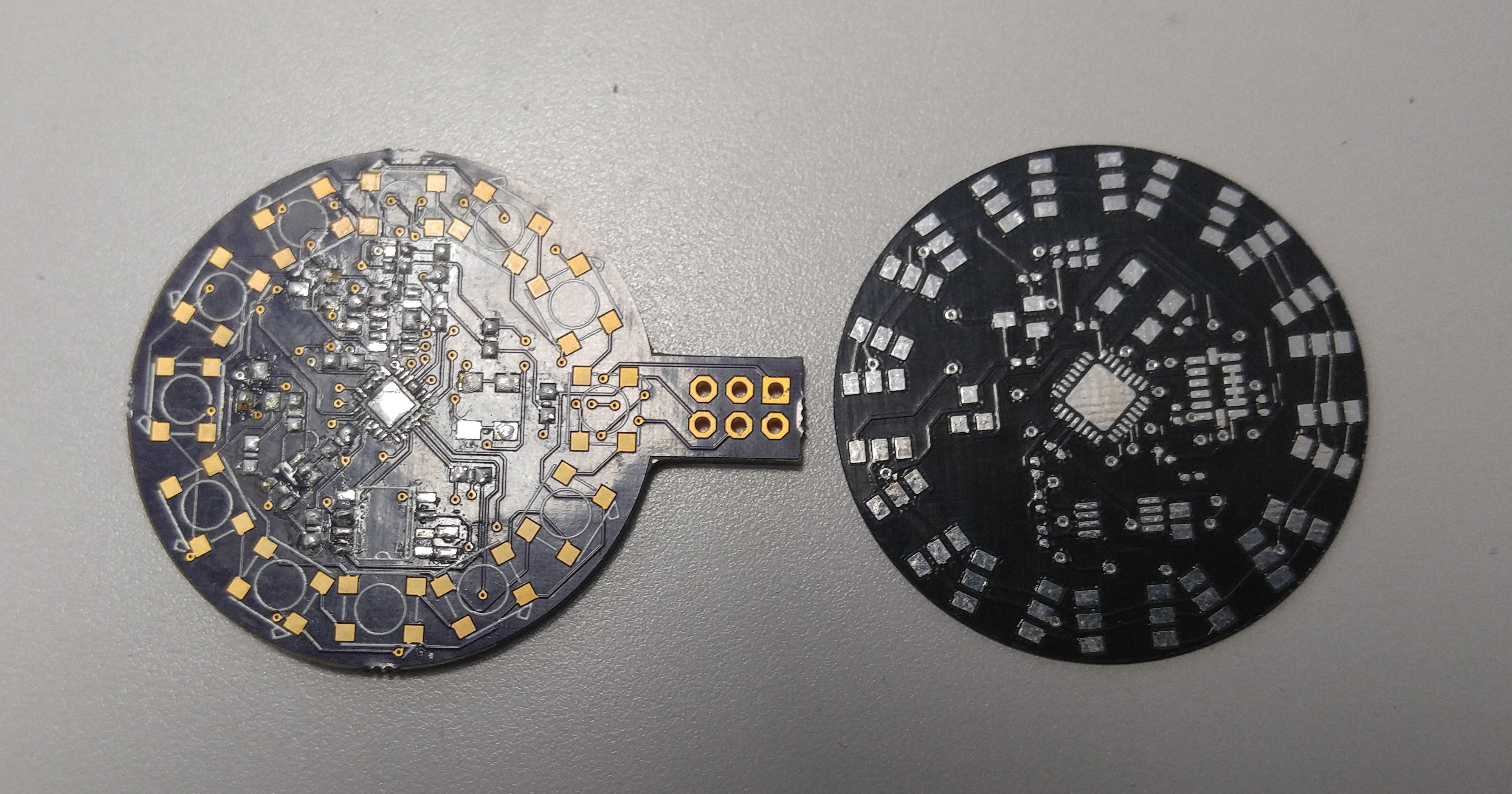
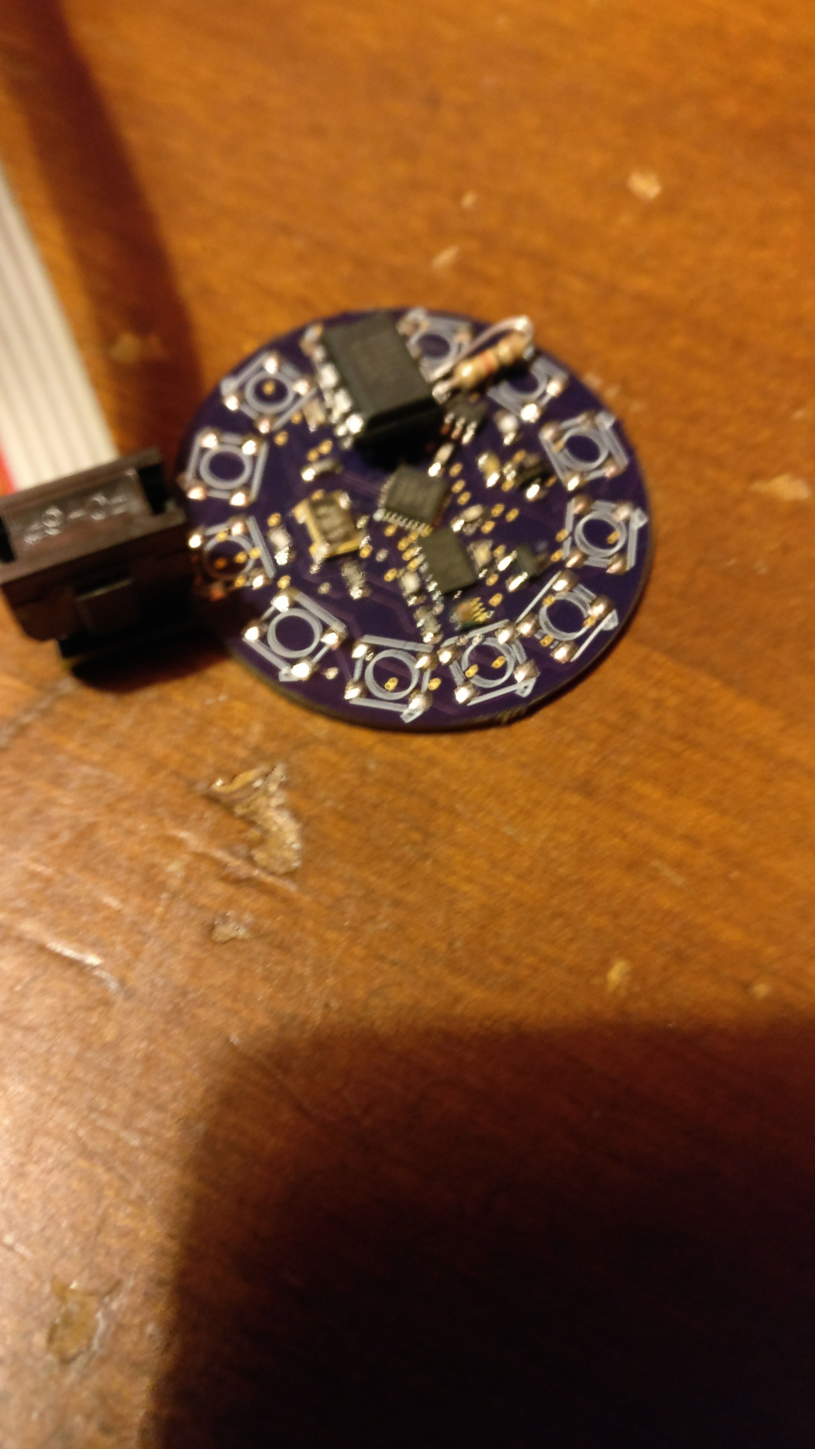
    The year began and we were soon beset by more problems with pad placement. The bootloading pins on the board were placed very poorly and the ATMega328p was difficult to solder. Bootloading was also an unnecessary process that could be sidestepped by using a pre-bootloaded ATMega328p from a Arduino Pro Mini clone. The result: a second board as shown below.

    Left is the poorly soldered board with bootloading pins, right is the thinner, sleeker board.


    Unfortunately, the black board shown above was the incorrect size for the watch case. The board did not sit correctly on the lip of the watch case. We ordered new boards that were 0.5mm larger in diameter.

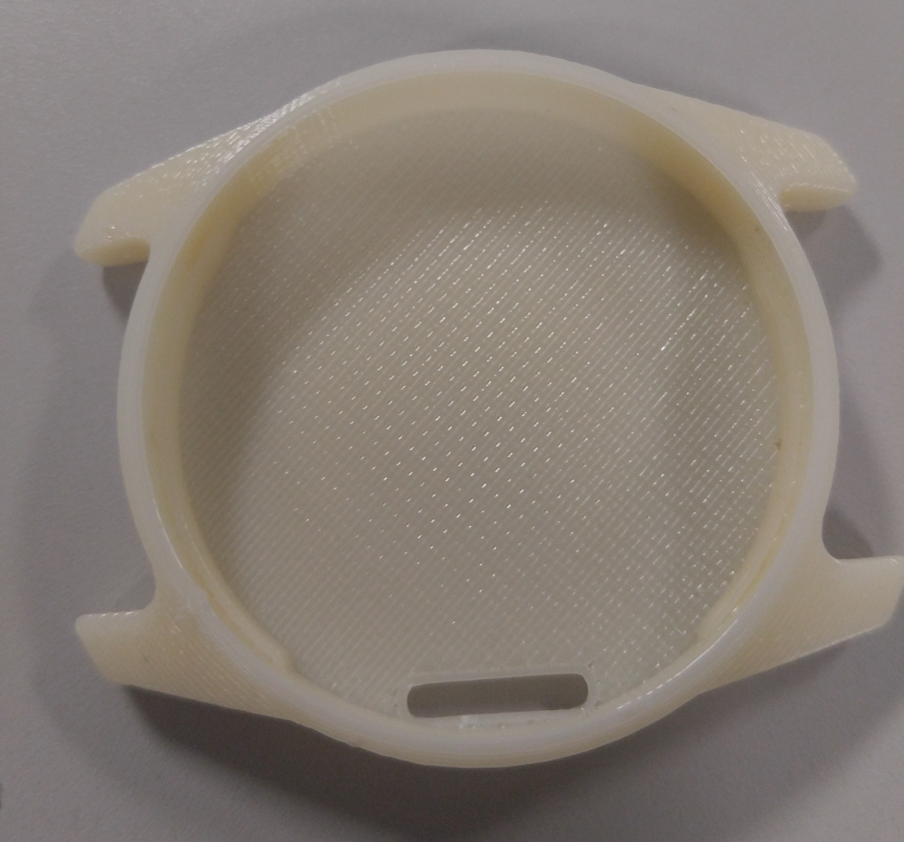
    Meanwhile, I began working on and revising the CAD model of the watch case and I also began considering watch strap ideas. Below is the most recent model of the watch case, which has been 3D printed in my shop.

    Notable features of this design include:

    • A small lip to hold the circuit board
    • About 7.1mm thick with an outer diameter of 40mm
    • A small slot in the bottom of the case for a charging port

    More about the charging port:

    • It is a contact method that allows us charge while retaining water resistance
    • This solution is cheaper than other water resistant methods, such as removable back and wireless charging
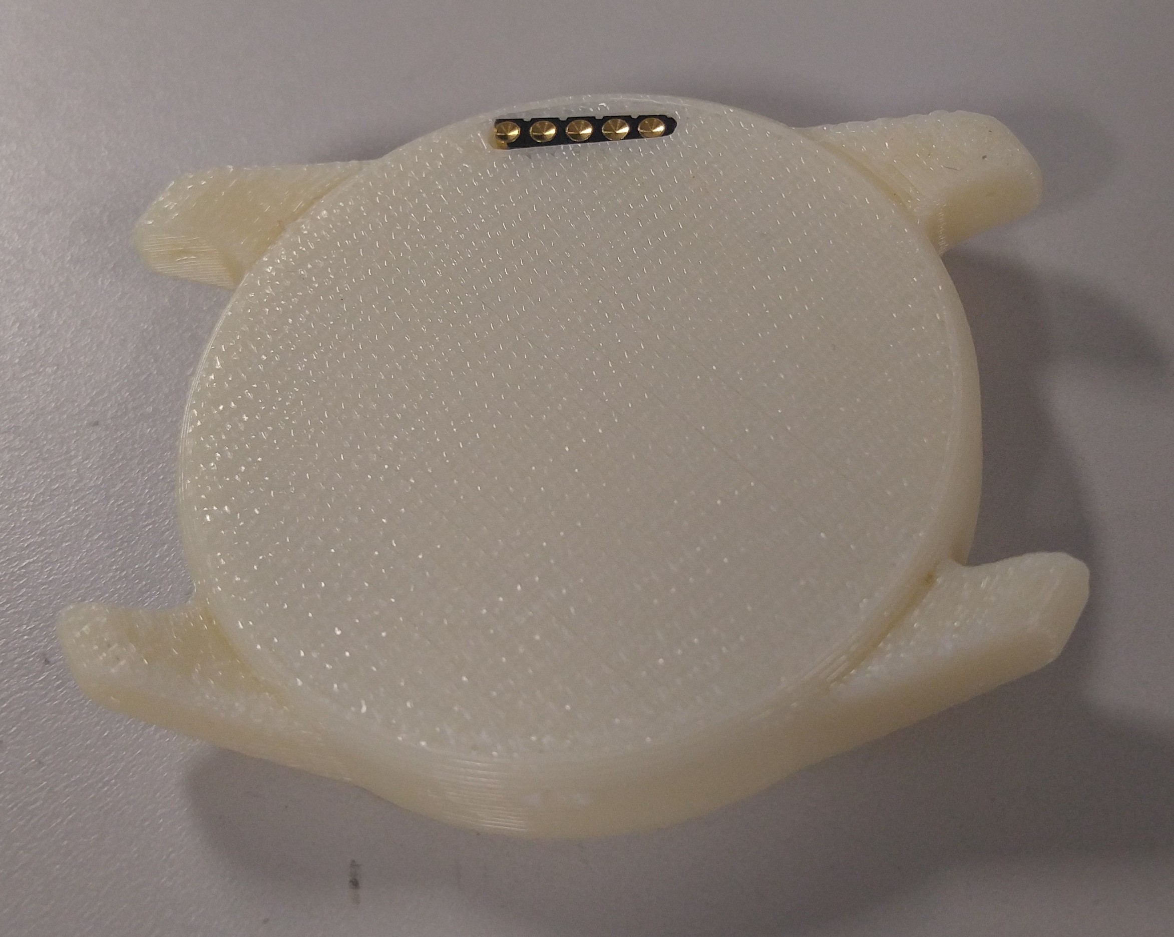
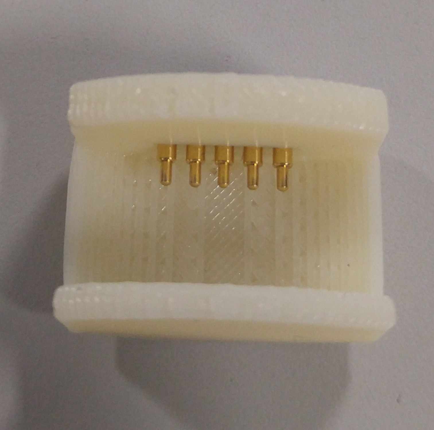
    • We have made a charging interface for the port using pogo pins (shown below)Here is a picture of the charging interface on the case:
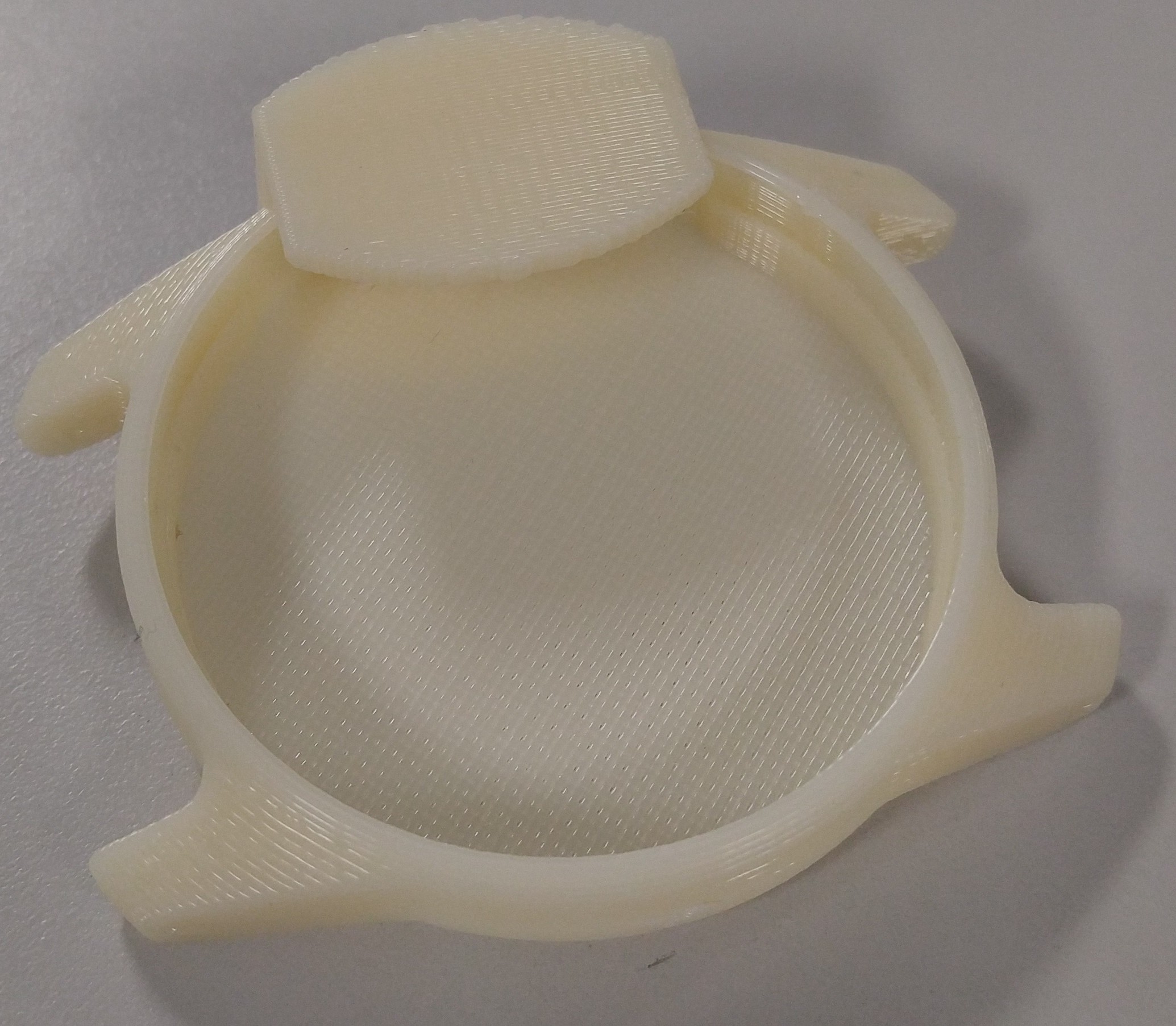
      You may be able to see a problem with the charging interface however. The pogo pins have a high chance of being being when placed on the watch case with this current design. The next design will include a snap-on mechanism to preserve the pogo pins.
    Next time on the Arduino Neopixel Watch:

    • Prototype Board Revision 3
    • New Charging Interface
    • Code Development

    Maybe I will also come up with a cool name for the watch as well...

    If you have any ideas or comments be sure to leave them on the project!

  • Neopixel Watch Progress: Winter of 2016

    Marcello Graves03/28/2017 at 15:17 0 comments

    After learning how to use eagle and making a schematic and board layout was designed the boards were ordered.

    Parts were purchased, mainly from Digikey, and were cheap and quickly shipped. Unfortunately, upon getting the boards weeks later, a mistake was made the on the pad layout of the real time clock, so in order to be able to test the circuit desperate things were done... We had to bend the leads of a DIP RTC in order to fit the misaligned pads, same with one of the resistors as well.

    Despite these challenged, we persevered and became closer to our goal!

  • Neopixel Watch Progress: Fall of 2016

    Marcello Graves03/28/2017 at 14:33 0 comments

    The project was shelved for a few months, due to not knowing how to continue and improve on the design in a way that could be accomplished at the time, mostly due to budget constraints and not having access to a 3D printer over the summer.

    During this time, several methods of an easy to implement an input method were brainstormed:

    • Button - would be too difficult to waterproof without a custom cap
    • Encoder - (like apple watch) cool idea but hard to fit into a watch with standard components
    • Accelerometer - (tap detection + gestures) easy to waterproof and implement into the watch

    After seeing a few other watches with an accelerometer as input I got the idea to use one, as it solves all the problems of being difficult to mechanically implement while being robust and water proof.

  • Neopixel Watch Progress: 2015

    Marcello Graves03/28/2017 at 12:53 0 comments

    Spring 2015

    • Purchased Neopixel ring, not really knowing what to use it for yet

    Fall 2015

    • Began generating concepts revolving around a watch-based project
    1. Use LED ring as digital display
    2. Use Arduino Pro Mini to control Neopixel ring

    Arduino Rgb Led Watch

    • Identified problems with current watch and smartwatch designs
    1. Short battery life
    2. Inaccurate time calibration
    3. Fragile hardware
    4. Bulky design

View all 10 project logs

  • 1
    Step 1

    Soldering the circuit board.

    Load a blink program onto the donor arduino pro mini clone, to make sure it works before you start doing anything else to it. After confirming it works load the neopixel strand test code on pin 7.

    Next use a hot plate to solder the Atmega328p as well as to desolder the ADXL345 from its brake out board.

    Next use a solder stencil to apply solder paste to the circuit board. I used a laser cutter to cut a stencil out of some adhesive vinyl, or you can order one from your board house.

  • 2
    Step 2

    Get the watch case 3d printed or milled if you are able to. I recommend getting it 3d printed in metal from shape ways in a material that is polished as it will save a lot of work down the road, you might be able to also find a cheap watch that has the needed inner dimensions, if so you would need to drill a hole and file it into a slot to be able to put the charging and programming connector.

  • 3
    Step 3

    Soldering the connector on the back using the 2mm concave headers is the hardest part as the headers need to line up with back of the case height, for this it is best to bend the header pins at a right angle and solder the tips to the pads on the back of the board. Then test fit it into the case making sure it lines up in height.

View all 7 instructions

Enjoy this project?

Share

Discussions

Marcello Graves wrote 04/25/2017 at 13:35 point

I considered about using the internal oscilator but i didn't want to have to change the bootoader on the atmega, and for the RTC I wanted it to be able to keep the time even after the main battery has died out because The time setting is probably going to be a pain. ill have to upload some pictures soon of the case as I just finished the main milling part of it out of aluminum.

  Are you sure? yes | no

bobricius wrote 04/25/2017 at 07:59 point

Nice but, you can use 32.768 crystall, run atmega with internall 8mhz RC oscilator, use TIMER2 in async mode and you have built in RTC with 1uA consumption in standby. I am using this for years in my watches...

  Are you sure? yes | no

Ember Leona wrote 03/31/2017 at 22:39 point

why what nice big tools you got there...I liked i was reminded of a SEARL engine 

  Are you sure? yes | no

Similar Projects

Does this project spark your interest?

Become a member to follow this project and never miss any updates