 Antti Lukats
After I figured out that this may actually work I could not hold back any more. Some of the resistors I found where 0402 size but they are still easy to solder on plain normal perforated prototype board. A few hours later I did see the radio signal received and converted to digital inside the FPGA.
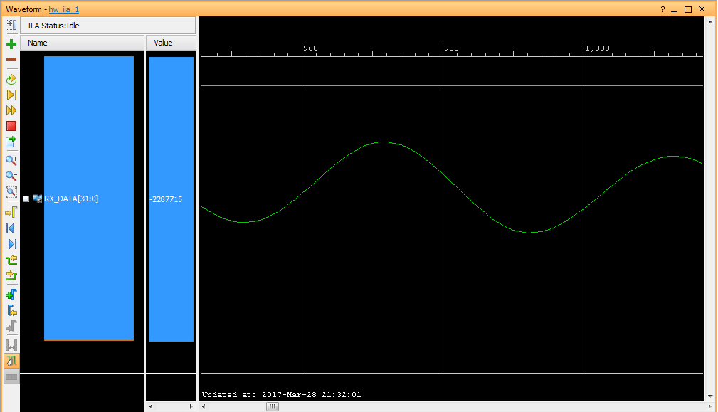
This is how 200 mV signal at 3.510MHz feed into FPGA using 4R4C Radio Receiver Circuit looks like.
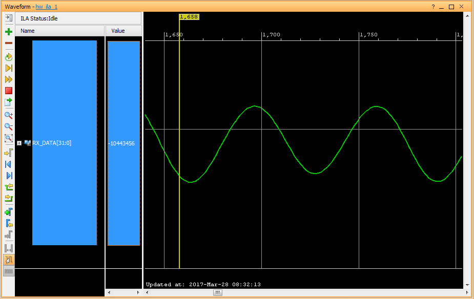
Ok and here we have signal at 200 microvolt. I had to build an attenuator to get signal level down.
Discussions
Become a Hackaday.io Member
Create an account to leave a comment. Already have an account? Log In.