 Antti Lukats
When I posted the challenge, assuming that the circuit works at frequencies 500 + MHz.
But I had not tested it.
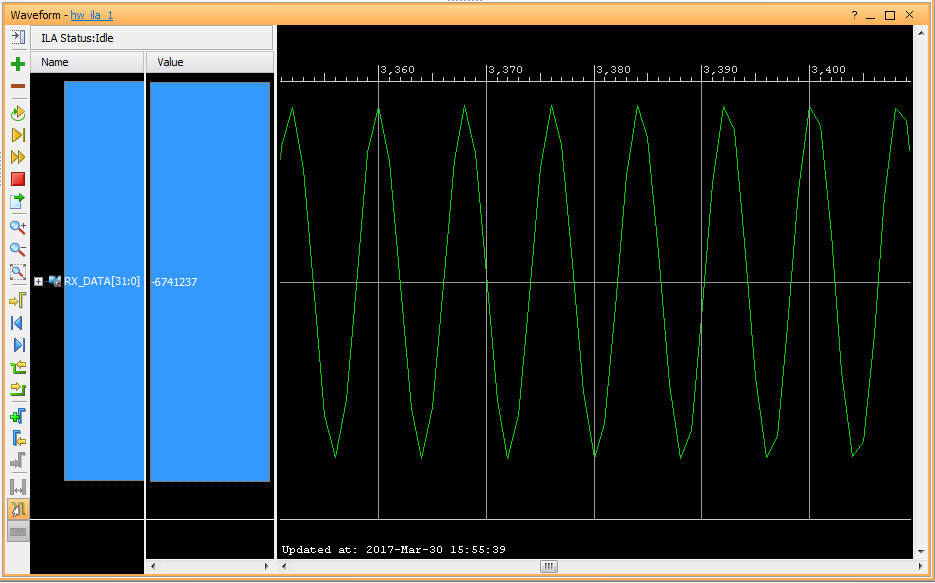
Now I have, this is 500MHz signal received with the same 4R+4C lab setup I used for first tests at 3.5MHz.
SNR is not good, actually its really really bad, but hey this is hand soldered prototyp on prototyping board, and the 500MHz frequency is pretty hard to some dirty circuit soldered on generic protoboard. Also the R and C values are not at all optimal, I did not change them, as I only wanted to see proof of concept that it works.
So basically the same circuit can receiver from below 1MHz to 500+ MHz.
Discussions
Become a Hackaday.io Member
Create an account to leave a comment. Already have an account? Log In.
No hints given, but as said in the challenge, the 4R + 4C + FPGA will create a Radio Receiver with frequency range from LF (below 1MHz) to 500+ MHz. This is possible even without changjng the R or C values. So really wide tuning range.
Are you sure? yes | no
Are you digitizing at 4GS/s ?
Are you sure? yes | no