 Jeff Wisgo
With one leg working, the next step is printing three more and switching from PLA to PAHT-CF, a stronger nylon filled with carbon fiber. Before spending that time and filament, I wanted to prove as much of the design as I can with this one leg. So I made a list of checks, ordered from safest to riskiest, and started working through it the same night.
| Check | What it shows | Result |
|---|---|---|
| 0. Walking gait | The leg can follow a planned foot path | Pass (Log 7) |
| 1. Zero after power cycles | The joint angles stay right after the power is cut, so no homing step is needed | Pass |
| 2. Full-range sweep | The cables don't pull, pinch or rub anywhere in the range | Pass |
| 3. Gravity hold | The leg's mass, its balance point and the motor's torque reading all match the model | Pass |
| 4. Free swing | Inertia and friction at the hip match the simulation | Pass |
| 5. Endurance | 30 to 40 minutes of walking, then a check for loose bolts, wear and heat | Next |
| 6. Foot press | The foot pushing down on a bathroom scale matches the force the motor torques predict | Next |
Zero after power cycles
The motors measure their output angle with a built-in sensor. If that reading drifted every time the power came back on, all the joint limits I measured by hand would be wrong after a restart, and the robot would need a homing routine. So I switched the supply off and on five times without touching the leg. The Mac read both angles three seconds after each restart and spoke a cue for the next one. The hip read 0.639 rad and the knee 2.700 rad every single time. The spread was zero, finer than the sensor's own steps of about 0.02°.
Full-range sweep
Each joint moved slowly to both ends of its range and held there, and then both joints went to all four corner combinations together. At every position I watched the cables at the thigh slot and around the hip. Nothing pulled, pinched or rubbed. This only covers the range I can reach on this rig, though. The simulation uses a wider hip range, so the cable routing needs another look before the robot uses all of it.
Gravity hold
The hip motor held the leg at six angles from 60° back to 35° forward, approaching each angle once from below and once from above, while the Teensy averaged the motor's own torque reading. Holding still, all of that torque is just the weight of the leg pulling down. I compared it with what the CAD model says the printed parts weigh and where their balance point is. The measured torque came out at 0.934 times the model, within 7%. The gap between approaching from below and from above shows about 0.05 N·m of friction.
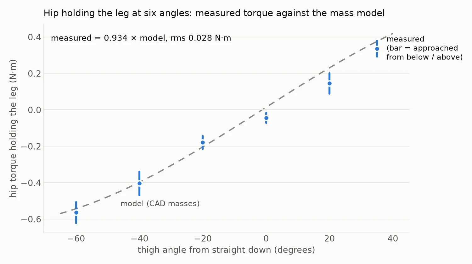
Measured hip torque against the mass model at six angles
That confirms two things at once. My method for working out each part's mass from the slicer settings works. And the motor's torque reading can be trusted even at these small loads, about 4% of its maximum.
Free swing
This one took a few tries. The idea was to lift the leg, let the hip go completely limp, and time the swings like a pendulum. The swing period depends on how much the leg resists being turned, its inertia. That includes the motor's spinning parts, which the simulation counts as extra inertia on each joint.
On the first try the leg sank slowly and stopped dead. The commands that switch the motor into its limp mode had gone out too close together, so the motor never switched and stayed in its "off" state, where it acts like a brake. With short gaps between the commands it worked, and the motor confirmed it was limp, but the leg still only sank to hanging without swinging. To rule out the motor's controller, I cut the power and dropped the leg by hand. It did exactly the same thing. So the drag is in the hardware itself, the gearbox and seals, and the light PLA leg barely outweighs it.
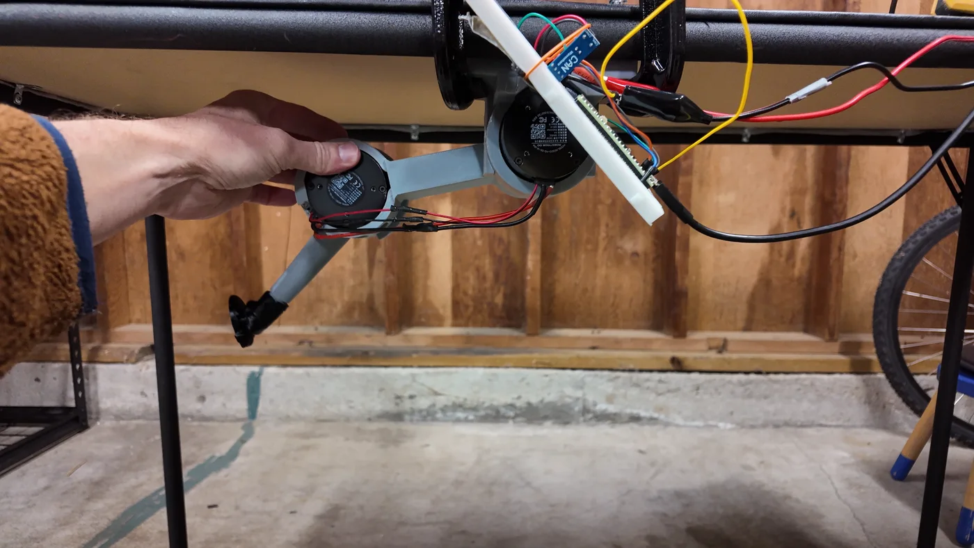
The unpowered drop test: lift the leg high and let go
Watching that video closely, though, the leg did swing past hanging once when I let it go from high up, then settled. One swing isn't enough to time a period, but there's another way. I simulated the fall with different values for inertia and friction and kept the one that matched the logged angle best. The match was very good, within 0.04° on average. Other inertia values didn't fit nearly as well.
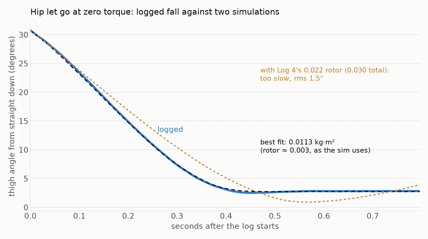
The logged fall against two simulations
The best fit puts the inertia at 0.0113 kg·m² about the hip. The leg's own share, from the CAD model, is about 0.0086, which leaves about 0.003 for the motor's spinning parts. That's the value the simulation has used all along. Friction came out at about 0.15 N·m, also close to what the simulation assumes.
This changes one conclusion from Log 4. There I wrote that the inertia from an earlier bench test stood, at about 0.022 kg·m². This test rules that out for the hip motor. My best guess is that the earlier test also counted the lever bolted to the motor, but I haven't checked that yet. Either way, the simulation runs I redid with 0.022 should go back to 0.003.
Next steps
The firmware for the last two checks is written and on the Teensy. The endurance run will loop the walking gait for 30 to 40 minutes, then I'll check every bolt and the knee and hip bosses for loosening, cracks or wear. The foot press puts a bathroom scale under the foot at the standing pose and pushes down in steps up to about 2 kg. The scale reading should match the force the motor torques predict. After that, one thigh in PAHT-CF and a small test piece for the heat-set inserts, before printing the full set.
Discussions
Become a Hackaday.io Member
Create an account to leave a comment. Already have an account? Log In.