 Artem Kashkanov
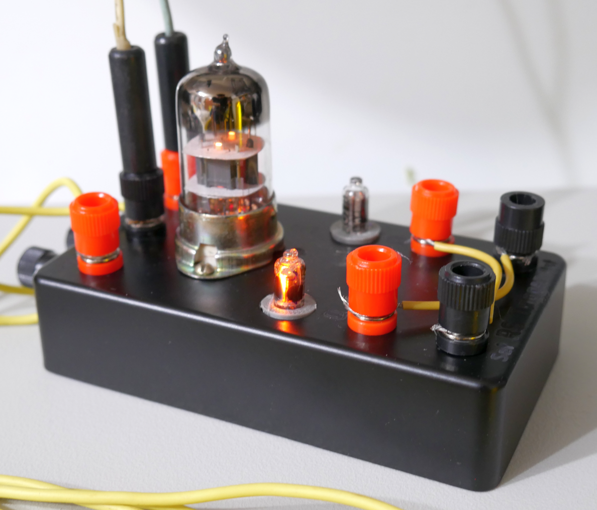
I started experiments with vacuum tube-based logic and decided to implement RS trigger on Double triode 6N3P
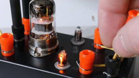
Here you can see, how it works in real:
So, It works. I used circuit from the IBM 604 manual and tried to simulate it as a first step:
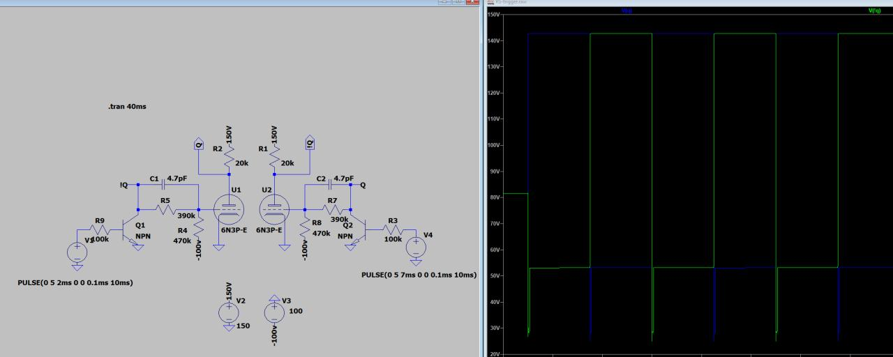
LT Spice allows me to check all nodes voltages and parts currents. There is no transistors in the real device - I used it just to driver the simulation model.
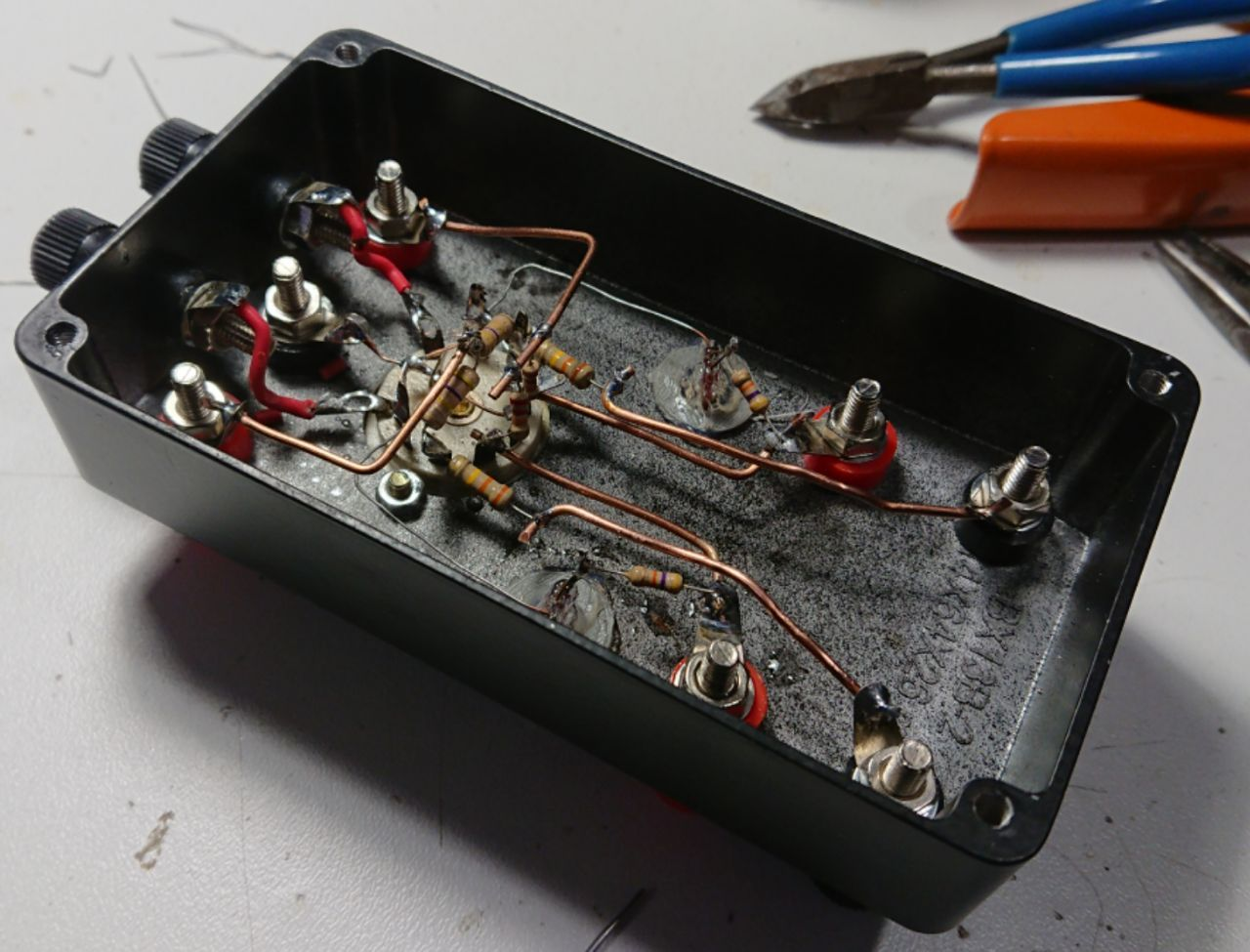
This is my first 3D-assembled device. It could be better, but...
There is +200V anode supply and -100V grid bias.
Logical levels for this schema - +150V for log.1 and +50V for log.0
Discussions
Become a Hackaday.io Member
Create an account to leave a comment. Already have an account? Log In.
Nice project :) Do you know how fast it runs? Is there a way for you to characterize the latch?
Are you sure? yes | no
How do you get those voltages ?
Are you sure? yes | no
I took a transformer from an old lamp TV and created a powerful PSU for Anode and heater voltages. It can give me 85-170-210-250 v with more than 0.5 Amp of current. Additionally, I use two-channel 350V 10mA for biasing.
Are you sure? yes | no
You did it ! :-D
Are you sure? yes | no