Close
0%
0%

BreatheDot: A Portable Meditation Aid

A small battery-powered meditation aid to keep you focused and refreshed wherever you go. - Available on Tindie!

Similar projects worth following
This is a small battery-powered meditation aid that is powered off a CR2032 battery. It uses an ATTiny85 and a single blue LED. By matching your breathing with the LED, you should feel the effects after 3 to 5 minutes.

The benefit of having a piece of hardware is that you can use it quickly and you don't have to strain your eyes looking at a screen.

It uses the box-breathing method used in yoga and the Navy Seals. Hopefully this project can help in promoting better health and well being.

> BreatheDot 2: https://www.tindie.com/products/25592/

I discovered the box breathing method on http://quietkit.com/box-breathing/. It has its roots in Yoga and can even be found in the Navy Seals. It is said to be effective in enhancing focus and promoting well-being and I have found this to be true personally. On occasion it has also helped me and others to defuse high anxiety situations. I then decided to make this device because I didn't want to stare at a screen to reduce possible distractions and eye strain. I wanted to be able to pull something out of my pocket and begin the cycle immediately.

I used an ATTiny85 to program it because initially it was what I had on hand. That turned out to be a good choice because it allowed me to run different programs and prototype different designs quickly without changing the hardware.

It is fun to fiddle with and nice to look at. A case of white plastic helps to soften the glow of the blue LED and keeps the electronics safe.

The LED follows a cycle of brighten (breathe in), lit (hold), dim (breathe out), off (hold). In order to indicate a change visually, gamma correction is provided for the PWM output of the LED because the human eye is not sensitive to changes in bright lights. A RGB version also fades from color to color that provides a visually appealing effect in addition to an increased perception of change.


Once this project is complete I will release the files and show you how to put the project together yourself. However do note that these are SMD parts so you might have to salvage a few parts yourself like resistors and LEDs. You can also buy them from Digikey for a few cents each.


All code, documentation and design on these project pages are licensed under the GNU General Public License (GPL) unless otherwise stated.


Comments? Questions? Ideas on how to improve? I'm always happy to talk in further detail about the design considerations. Just leave a comment below.

Currently I am working on a new version. There is an option of purchasing some on Tindie for those who want to experiment with one without going through the hassle of putting one together.

https://www.tindie.com/products/ulcek/breathedot-2-2/

amuletv3.1.sch

BreatheDot form factor with APA102 RGB LED

sch - 89.68 kB - 10/20/2017 at 12:54

Download

amuletv3.1.brd

BreatheDot form factor with APA102 RGB LED

brd - 43.21 kB - 10/20/2017 at 12:54

Download

gerber.zip

Design files for the original BreatheDot with 0603 LED

x-zip-compressed - 18.67 kB - 10/12/2017 at 02:41

Download

amuletv3.sch

Using a WS2812b LED/Neopixel for a more captivating display but a shorter run time. Long form factor

sch - 85.57 kB - 09/02/2017 at 14:42

Download

amuletv3.brd

Using a WS2812b LED/Neopixel

brd - 41.24 kB - 09/02/2017 at 14:42

Download

View all 8 files

View all 7 components

  • A new meditation focus mechanism

    Ben Lim12/23/2021 at 10:44 0 comments

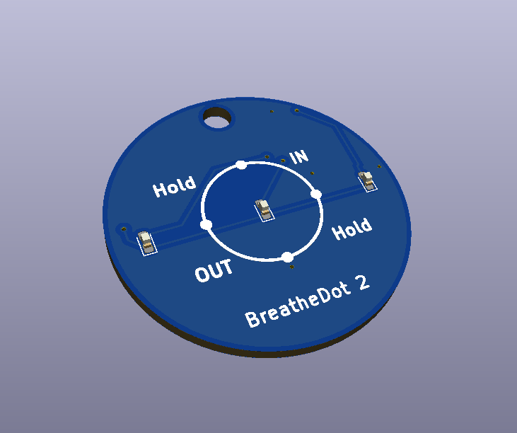
    I experimented with a few potential focus images, and the one that I liked best is this:

    Each quadrant represents what to do and it is very soothing for the eye to go in a circle. Before this I also tried it being a line and a sine wave that bounced back and forth, but those did not really work out. However I have high hopes for this particular design, especially since the LEDs are a bit clearer about when to move through each stage.


    Also added a keychain hole that was missing from earlier editions. However, this means that the BreatheDot 2 is larger ~ 32mm across.


  • Padauk development

    Ben Lim12/21/2021 at 13:50 0 comments

    I want to use Padauk, but I want to try out a new lighting scheme.

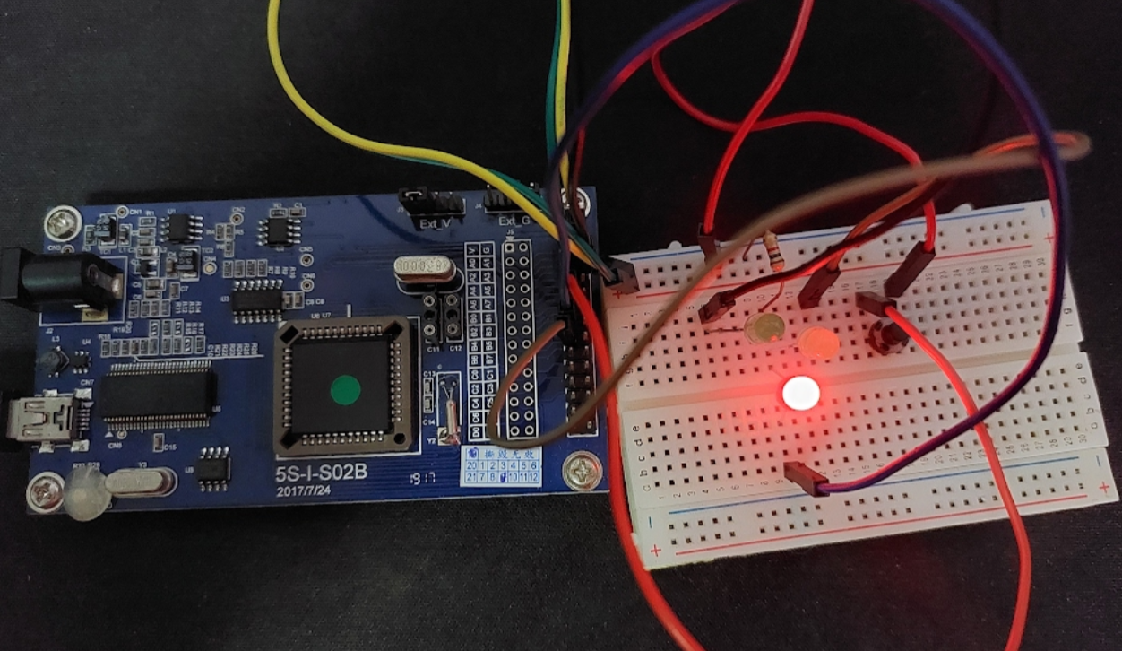
    This is the initial test of using 3 LEDs. The issue with a single LED is that it is sometimes hard to sense the transition between states. With these three LEDs it should be much easier to follow along, but the question I have is that if it is intuitive, because with the Single LED, all you have to do is match the LED, but here you are actually counting the LEDs.


    I'm also experimenting with different colors to represent different states.

  • BreatheDot 2 - Global component shortage

    Ben Lim12/18/2021 at 02:32 0 comments

    Due to the global components shortage, I am forced to redesign the BreatheDot 2 with another device because my preferred ICs are either too expensive or simply out of stock.


    Recently I have been interested in the Padauk ICs and have had a few successes in implementing them in my other projects. While they are not easy to source or program, the benefit is that they are really inexpensive, which helps to offset the other difficulties in my eyes.


    I am planning to redesign the BreatheDot 2 to use the PFS173 from Padauk. It is a MTP part and is quite easy to solder.

  • BreatheDot 2

    Ben Lim12/14/2021 at 15:10 0 comments

    Read the full post here: https://westsideelectronics.com/breathedot-2/

    I finally came around to updating the original BreatheDot design. The interface was a little challenging to use and it didn't last very long.


    Upgrading the Breathedot to use an STM32 really improved the quality of life for me as the designer and programmer, and it offers a better interface. Now the whole PCB can be used as a button, and it goes into sleep mode, allowing for the battery to last years on daily usage.

  • Programmable RGB Led

    Ben Lim10/20/2017 at 12:53 0 comments

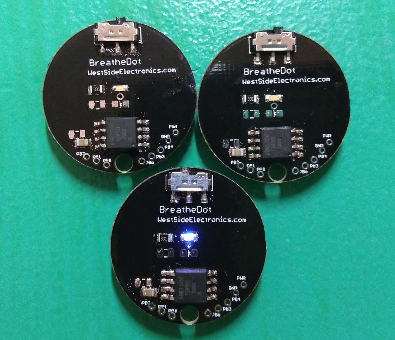
    I finished and tested a new version of the BreatheDot that is the same form factor but now features a programmable APA102 2020 RGB LED. You can use Adafruit's Dotstar Library to program it.

    I always wanted to do it because I really like RGB lights and I find the effect of fading from color to color to be quite mesmerizing. The photo is in the gallery, and the design files have been uploaded as v3.1. It uses a single CR2032 battery to run the LED and the ATTiny85. The Data Pin is PB1 and the Clock Pin is PB2.

  • [Edit] Instructions uploaded

    Ben Lim08/02/2017 at 15:13 0 comments

    I wrote up a list of instructions in order to program the Attiny. It is set up in such a way that reprogramming will be easy.

    I have tested the instructions and they should work smoothly. This was done in a Linux system, but you can subsitute the commands for those of a Windows system if you are using it to program the ATTiny85.

  • More lights, all the lights

    Ben Lim05/26/2017 at 13:30 0 comments

    I designed a new board that uses 2 CR2032 batteries and a WS2812b/Neopixel. I had my concern about how much the power draw will be, but I have been playing with it for over 3 days and it seems to work fine. I forgot to add a diode to drop the voltage to the ATTINY85 (safe levels are 5.5V), but there are no glitches.

    There are programming headers now for easier reprogramming. However it is not compatible with a breadboard yet. I used one of my headless Digispark devices to program the Breathedot.

    The nice thing about his new Breathedot (or BreathePixel?) is that the RGB colors are really pretty and the board provides more space to add other things like sensors or a IR receiver or light sensor.

  • Wow!

    Ben Lim05/10/2017 at 01:28 0 comments

    Hello! This is quite an unexpected piece of good news. This project was chosen as one of the top twenty for the Hackaday Design Your Concept Entry! Thank you all for your support and comments.

    Moving forward there are a few changes that I want to explore, adding a graphic for people who like the PCB as it is, and switching out the LED for a WS2812b or a Neopixel. This will test the battery life however, and it remains to be seen what the current draw will be. I have been able to successfully power 10 neopixels off 2 CR2032 batteries over an hour of usage, so this might be a promising avenue to look down.

  • New Boards

    Ben Lim05/08/2017 at 22:55 0 comments

    Hello!

    New boards are in, and they will be available on the Tindie page!

    They are black, white and silver, as promised.

  • Making Boards

    Ben Lim04/19/2017 at 20:20 0 comments

    So I have had some interest in people wanting to buy boards/finished BreatheDots so I am currently making a few of them, they should be here within the next two weeks!

    In honor of Hackaday, these boards will be in black, white and silver. A pretty classy combination I think. If you'd like one, just make a note on my Tindie page and I'll let you know as soon as they are done.

View all 16 project logs

  • 1
    Programming

    Task: Program your ATTiny85 chip with micronucleus firmware: https://github.com/embedded-creations/micronucleus-t85

    You should have Arduino installed on your system.

    Using an Arduino as ISP, wire up the ATTiny85 chip for programming. You have two options to do this:

    • You can do this for an SMD ATTiny85 by using a breakout board. Adafruit sells these. NOTE THAT YOU WILL NEED TO DESOLDER. I found the best way is to use a hot-air gun for desoldering.
    • You can also directly solder the ATTiny85 onto the board and wire up the board to the ISP the vias using anything above a 24 gauge wire.
    VCC->5V  
    PB5->10  
    PB2->13  
    PB1->12  
    PB0->11  
    GND->GND   

    Run the following code to upload (edit the green code to the path of the micronucleus hex file):

    avrdude -c arduino -p t85 -b 19200 -P /dev/ttyACM0 -U flash:w:'.../t85_default.hex' -U lfuse:w:0xe1:m -U efuse:w:0xfe:m -U hfuse:w:0xdd:m

     Upgrade the micronucleus firmware to micronucleus-1.06-jumper-v2-upgrade.hex. I used an old Digispark that had a desoldered ATTiny85 and wired up the newly programmed ATTiny85 to its breakout pins it so that I could communicate over USB. Once connected, I ran the upgrade hex over micronucleus to remove the 5 second delay.

    micronucleus --run 'micronucleus-1.11-entry-jumper-pb0-upgrade.hex'

    Upload the code for the BreatheDot after the micronucleus firmware has been loaded by grounding Pin 0 on the ATTiny85, and uploading the code through Arduino.

     You can either export the code as an hex file and upload it with micronucleus or you can install the Digispark definitions and upload it through Arduino.


    You can also program it over the Arduino ISP by running the same code but changing the path of the file. Remove the lines to set the fuses:

    avrdude -c arduino -p t85 -b 19200 -P /dev/ttyACM0 -U flash:w:'program.hex' -U lfuse:w:0xe1:m -U efuse:w:0xfe:m -U hfuse:w:0xdd:m
    

    Upload the final code for the program by exporting the code as a hex file and uploading it via the Arduino ISP.

  • 2
    Soldering

    Solder all parts on board. Parts list is provided as part of project description. You will need a 1k resistor for the soldering pad near the LED, which should be centered on the board, and a 0.1uF capacitor for one of the soldering pads near the ATTiny85. If your LED doesn't light up, try changing the orientation of the LED. Remember to align the ATTiny85 to the silkscreen.

  • 3
    Test
    1. Test PWR and GND pins are not touching.
    2. Test PWR is connected to VCC line when switch is turned on
    3. Test VCC is touching the VCC pin on the ATTiny85
    4. Check no pins are touching
    5. Check that LED is soldered in the right direction

View all 3 instructions

Enjoy this project?

Share

Discussions

Wilpe wrote 10/20/2017 at 10:33 point

If I programm the attiny while its not soldered to the board do I need the vias for PB0 - PB5 and PWR?

  Are you sure? yes | no

Ben Lim wrote 10/20/2017 at 12:25 point

Nope. They are for reprogramming and to test if the Attiny is soldered correctly.

  Are you sure? yes | no

Wilpe wrote 08/02/2017 at 14:17 point

Do you have a rough date when you will be able to release the code?

  Are you sure? yes | no

Ben Lim wrote 08/02/2017 at 14:51 point

Woah! I thought I uploaded it. I placed the latest code that is working in the files. It doesn't have the blink. Sorry for the delay. Working on a few new ideas on improving the project

  Are you sure? yes | no

philippe.clair wrote 02/17/2021 at 01:22 point

Dear Lim, is there any chance that you upload the code ?

  Are you sure? yes | no

Ben Lim wrote 12/14/2021 at 15:14 point

Hello, the code is uploaded under files. Do check out the BreatheDot 2 though! It has several new improvements that make it easier to use:
BreatheDot 2 

  Are you sure? yes | no

Michael Stoiko wrote 07/31/2017 at 13:06 point

A suggestion I was mentioning to Ted: Adding a bi-color LED to indicate inhalation and exhalation (or two, or whatever). The other thing that might be helpful could be a "count" led that keeps time to help the breaths stay even (pulses every second)

It depends on the aesthetic you are going for, however.

  Are you sure? yes | no

Michael Stoiko wrote 07/31/2017 at 15:24 point

Reading back, I see the issue with draw. For some reason I couldn't see the earlier logs. Since your MCU has plenty of capacity available, add a PIN photodiode (to be energy neutral) and have the ADC read the value at startup and use that to adjust the brightness to ambient conditions?

IE Scale the top and bottom PWM values using the coefficient you derive from that ADC read.

  Are you sure? yes | no

Ben Lim wrote 07/31/2017 at 15:33 point

That makes sense. I will experiment with the bicolor LED, as well as using the PIN photodiode for ambient detection. Thanks for the comments!

  Are you sure? yes | no

Ted Yapo wrote 07/28/2017 at 13:42 point

I really like this concept.  I think it would just be a matter of software changes to implement this on a  #TritiLED , which would run for years on the same battery.  Would you mind if I borrowed the idea and implemented it on my hardware as part of my project?  I'd like to make a sealed one that just works for 10 years or more.

  Are you sure? yes | no

Ben Lim wrote 07/29/2017 at 08:26 point

Hi Ted, sure thing! Could you perhaps keep me in the loop? I'd like to see one that can last that long as well. I saw your project, it is very cool. Do you mind if I adapted some of your designs to lower the current draw as well?

  Are you sure? yes | no

Ted Yapo wrote 07/29/2017 at 13:03 point

Yes, go for it!  See also #ATtiny45 EverLED  for an implementation of the low-power ideas on an Atmel part.

I'll be sure to let you know what I come up with.

  Are you sure? yes | no

Alyssa wrote 05/12/2017 at 15:21 point

This is so lovely!! So proud of you C:  also i lowkey want/need one hehe

  Are you sure? yes | no

Ben Lim wrote 05/13/2017 at 12:48 point

Thank you!

  Are you sure? yes | no

Frank Buss wrote 05/10/2017 at 07:02 point

How did you implement the fading? If you use PWM, then you need bigger steps the brighter it gets, because the human eye perceives changes much better when it is dark, but not when it is bright. I did some tests and provided an Arduino example with the logarithmic formula to make a smooth fading, see here:

https://hackaday.io/project/20474-antique-nixie-clock/log/56827-pwm-test

This might solve your problem, that the users can't see when it starts to fade.

  Are you sure? yes | no

Ben Lim wrote 05/10/2017 at 12:52 point

Oh wow thank you! This is super helpful.

I'll take a look at the code.

  Are you sure? yes | no

Frank Buss wrote 05/10/2017 at 13:18 point

You can see it in this script:

https://github.com/FrankBuss/nixie-clock/blob/master/pwm-test/fade-test/fade-test.ino

in the initFadingTable function. The explanation for the formula is here:

https://www.mikrocontroller.net/articles/LED-Fading

Sorry, it is in German, but Google translate should help, if you don't speak German. But I can try to explain it, too, if you need help with it.

  Are you sure? yes | no

Ben Lim wrote 05/10/2017 at 13:57 point

Oh nice! 

Thank you for providing the additional explanation!

  Are you sure? yes | no

Wilpe wrote 05/10/2017 at 05:00 point

Will the boards also be available in Europe? I wanted to buy one from tindie but they are only shipped in the US.

  Are you sure? yes | no

Ben Lim wrote 05/10/2017 at 12:46 point

Shipping to Europe costs quite a bit currently. The last time I tried it was about $13.50 for a single package. However, I am open to digging around to find a cheaper option if you are!

  Are you sure? yes | no

Wilpe wrote 05/10/2017 at 13:50 point

I know.. shipping is realy expansiv from the US to Europe. You could get similar big items from China for under 1$ :(

I would order two boards if shipping was cheaper..

I would also collect orders from fellow Germans and forward it to them. But I guess this might be the wrong place to collect orders..

  Are you sure? yes | no

Ben Lim wrote 05/10/2017 at 14:03 point

Actually the additional costs of shipping one or more is around the same cost. It is just the base cost that costs $13.50 because how much one packet costs. 3~4 can probably fit into the same package if that helps!

  Are you sure? yes | no

Wilpe wrote 05/10/2017 at 14:08 point

If its allowed and possible..

A First-Class Mail® International Large Envelope** is only around 5$.

  Are you sure? yes | no

Ben Lim wrote 05/10/2017 at 14:15 point

I think that might be worth attempting! I'll have to check with the local post office for the rate however. At the moment I'll set the shipping option to what I have experienced.

  Are you sure? yes | no

Wilpe wrote 05/16/2017 at 07:12 point

Did you have a chance to check with your post office?

  Are you sure? yes | no

Ben Lim wrote 05/16/2017 at 13:45 point

I did. However because the product is electronic and I want to ship it in a bubble wrap envelope, it is classified as a package and not a large envelope.

At this price it doesn't make sense to ship the product. I would encourage you to build your own, since I suspect it'll be much cheaper. I have posted the board layout and you can get it made at a pcb manufacturer.

I am currently waiting for a improved board that uses a RGB led, and if it works out I'll share the schematic here!

  Are you sure? yes | no

Wilpe wrote 05/17/2017 at 07:19 point

You are right. I will try to make it myself. Could you please upload the layout as a pdf, brd or png?

  Are you sure? yes | no

Ben Lim wrote 05/17/2017 at 13:44 point

Oops! I thought I uploaded the board. Both the new board and schematic are uploaded! 

  Are you sure? yes | no

cabalist wrote 04/16/2017 at 01:29 point

Just got one off your tindie page.  Looking forward to seeing the code and files.  :)

  Are you sure? yes | no

Ben Lim wrote 04/18/2017 at 18:06 point

Thank you!

  Are you sure? yes | no

Youlian Troyanov wrote 04/15/2017 at 05:18 point

this is really cool. how much will it cost to build a  dozen and ship it to, say, toronto, canada?

  Are you sure? yes | no

Ben Lim wrote 04/15/2017 at 14:24 point

It is available on my Tindie page! Currently it is $9.95 for a single item. However, if you're interested in buying more we can definitely work something out. 

  Are you sure? yes | no

qquuiinn wrote 04/10/2017 at 07:39 point

This is a really cool project. Wish I thought of it first :D Perhaps add a pushbutton with interrupt to turn the attiny on and off? Otherwise best of luck and I'll keep an eye out on Tindie for you.

  Are you sure? yes | no

Ben Lim wrote 04/10/2017 at 17:26 point

Hi qquuiinn! Thank you!

The board actually has a switch to cut off the power entirely, so there is no need for sleep modes and interrupts. 

  Are you sure? yes | no

Wilpe wrote 05/17/2017 at 18:11 point

  Are you sure? yes | no

Ben Lim wrote 05/18/2017 at 03:21 point

http://www.mouser.com/ProductDetail/Linx-Technologies/BAT-HLD-001/?qs=sGAEpiMZZMvxqoKe%2bDjhrjh/wlHbZaKUC3Xc27YzfD8= This is the one that I use. Yours might fit, but I'm not sure the footprint is the same.

  Are you sure? yes | no

Ben Lim wrote 05/18/2017 at 03:21 point

I can look around a little if you can point me to any German websites that are like Digikey or Arrow

  Are you sure? yes | no

Wilpe wrote 05/19/2017 at 05:46 point

I thonk the second one i posted should work. It has a similar footprint as yours: http://downloads.cdn.re-in.de/1000000-1099999/001009388-da-01-en-RENATA_KNOPFZELLENHALTERUNG_SMTM2032.pdf

And what switch where you refering to, in the reply to qquuiinn?

  Are you sure? yes | no

Ben Lim wrote 05/19/2017 at 12:53 point

I posted the model of the switch on the BOM.

Great! The pads on the side might be a little larger than what I have on my PCB layout so you might want to switch in the actual footprint on the board.

  Are you sure? yes | no

Ember Leona wrote 03/31/2017 at 15:42 point

Can either of you explain an orgone pyramid to me?

  Are you sure? yes | no

openInvent wrote 03/31/2017 at 03:56 point

you should combine this with my zork glowstone project. I really wish that would detect radiation levels and be a pocket zorkstone

  Are you sure? yes | no

Ben Lim wrote 03/31/2017 at 13:48 point

Hello! That would be a pretty cool project, however a radiation detector requires high voltages. The components would not be able to fit on the footprint of a coin cell battery. Can I suggest a light sensor instead? That way the glowstone reacts to the environment as well.

  Are you sure? yes | no

Ember Leona wrote 03/31/2017 at 15:40 point

Thanks for the feedback on the highvoltage thing dont thing i can have a microscopic tesla coild just yet... 

  Are you sure? yes | no

Richard Hogben wrote 03/31/2017 at 14:46 point

What is the zork project?

  Are you sure? yes | no

Ember Leona wrote 03/31/2017 at 15:41 point

a UV led with glow ing the dark paint in a toy case from those coin vending machines.

  Are you sure? yes | no

Similar Projects

Does this project spark your interest?

Become a member to follow this project and never miss any updates