 elmameto
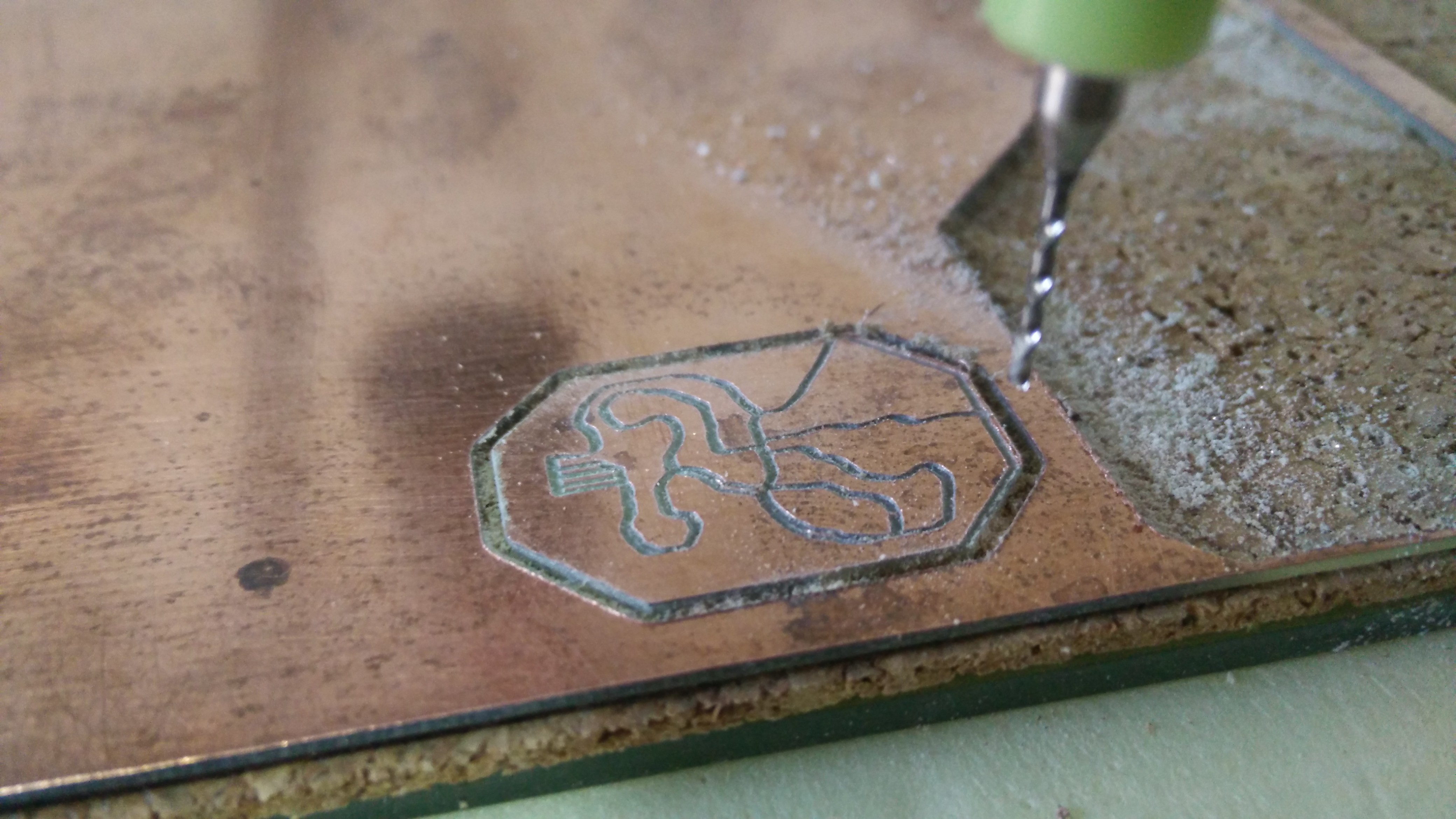
As said before, the controller will feature an internal battery charger. Today I decided to use the MCP73831, so I rapidly drew a schematic (to be honest, I just copied the typical application from the datasheet) and carved it on the CNC.
Again, a wofis (worked on first shot).
It's made with tht components, but on the final board will be smd, which means ridiculously small.
Love it when things just work
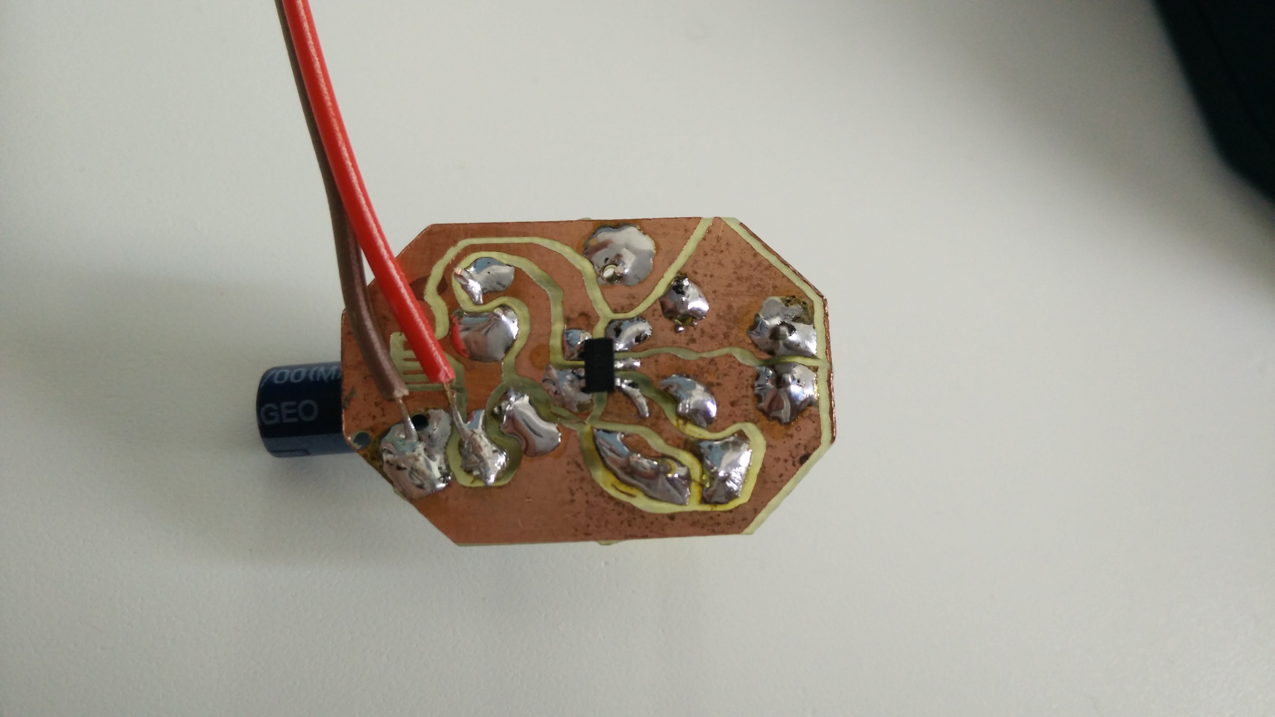
Easier to solder than I thought
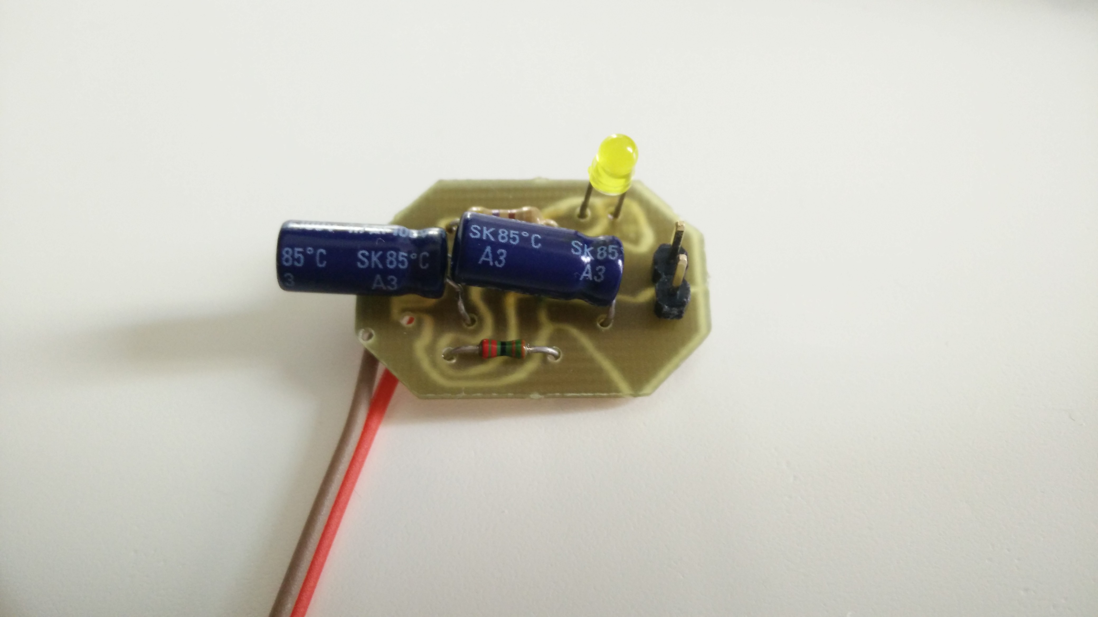
The LED turns on when charging, off when battery full or disconnected.
Really happy with the result, totally recommend the device. I will not upload this schematic because it's not strictly part of the controller, but something very similar will appear on the final version :)
Still, you can get the schematic for this standalone version at GitHub/elmameto/chargy
Discussions
Become a Hackaday.io Member
Create an account to leave a comment. Already have an account? Log In.