 davedarko
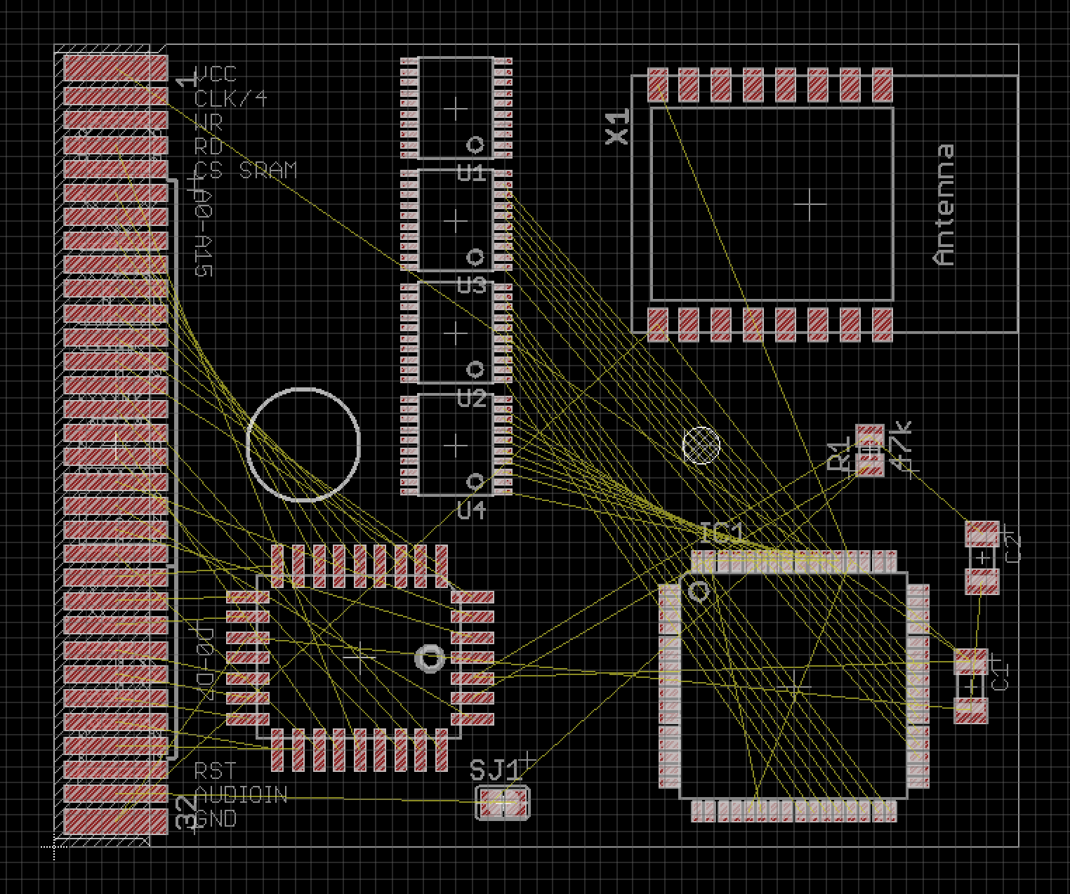
Starting from my #Game Boy Cartridge plus Programmer designs, I tried to add some parts and lay them out, to get a feeling for it. I still need power conversion and am thinking about adding a separate power source for the ESP side.
To Recap the Idea:
- the ESP12 will behave like a Memory Bank Controller (MBC) that handles the bus traffic, meaning who is asked for and who will talk (I still hope I have enough pins left)
- the AVR (AT90USB1287) will be connected via SPI to the ESP12 if it is to slow, I could just ask it twice or three times for the value to make sure I have the right data
- the ESP would know that the AVR has to be enabled, instead of the EEPROM, so it needs to be able to enable or disable them
- I need some level-shifting on the board from 3.3V to 5V and the ESP is quite power hungry, so maybe I'll add lots of caps or another battery
Discussions
Become a Hackaday.io Member
Create an account to leave a comment. Already have an account? Log In.