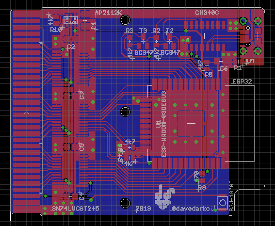
I'm scared of that rats nest of wires on a breadboard that is hidden in a box. Thanks to some experience I gained with using IO0 and IO2 as a regular pin, I know that it's okay to use them as the missing two address line pins. I might steal one of them back to be able to reset the game boy, as I don't think using one of the serial pins is a good idea, especially if you want to have a serial debug terminal ;)
With less address pins the programs written / compiled for should adjust memory bank switching for smaller banks. I think that's doable.
Not sure if I said this here, but I was able to run the I2S parallel code on the ESP32 and that gave me hope. After a lot of unexpected twitter feedback about groundplanes and copper tunges, I made some changes and this is what I came up with. Cleanly routed, doesn't fit any reproduction cartridges, but form follows function, right? There's even a 1M ohm connecting the usb connector shield to Ground (not even sure if this is 100% necessary, but better safe then sorry, right?
Power consumption of the ESP vs. 4 AA batteries inside a DMG or even worse - 2 AAA batteries inside a GB Pocket is still an issue with this board. The plan is to have one AAA LiPo added to a later revision of the board. To get an idea how this could look like, check out the Pokemon Pinball cartridge, or any Game Boy rumble cartridge for that matter. This design is supposed to be powered over USB, since it's a dev / debug board.

 davedarko
Discussions
Become a Hackaday.io Member
Create an account to leave a comment. Already have an account? Log In.