 Marcel van Kervinck
-
Updated grammar using EBNF
03/12/2018 at 18:15 • 0 commentsWith ROM v1 done and arrival of the last kit parts confirmed for this week (yeah), now is the time for chores. The syntax I used for writing the apps has some rough ends. It was grown bottom-up, hand in hand with the GCL-to-vCPU compiler, while vCPU was still evolving. As I'll need a new compiler for the Arduino interface anyway, why not fix what can be fixed? So now here is the formal EBNF definition of the updated notation, or call it a language if you wish.
![]()
There is a great online visualizer that turns these grammars into easy-to-understand railroad diagrams. I've always liked these since I first encountered them in the "Pascal User Manual and Report". A webpage with all diagrams sits here on HaD.
![]()
GCL will never look pretty, but it at least it isn't Perl.
-
Small hiccup, but almost there!
03/04/2018 at 15:41 • 0 commentsWith great anticipation we received our last parts for the batch last week. Panic ensued when we discovered they were of the wrong type. Not a few, all of them... Did we place a wrong order? Frantic discussions with the supplier followed and yesterday it became clear: they messed up, apologised, and they are now sending us a new batch. We expect the total impact will be a two-week delay. Bummer, but at least we didn’t lose any money on a stupid mistake.
![]()
So please bear with us a little bit longer, soon you will be heating up your soldering iron!
-
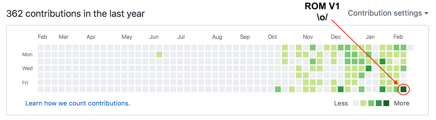
TTL computer ROM is feature complete
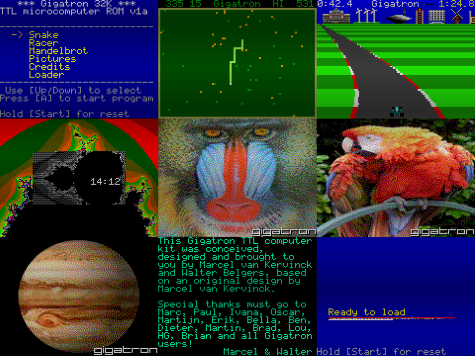
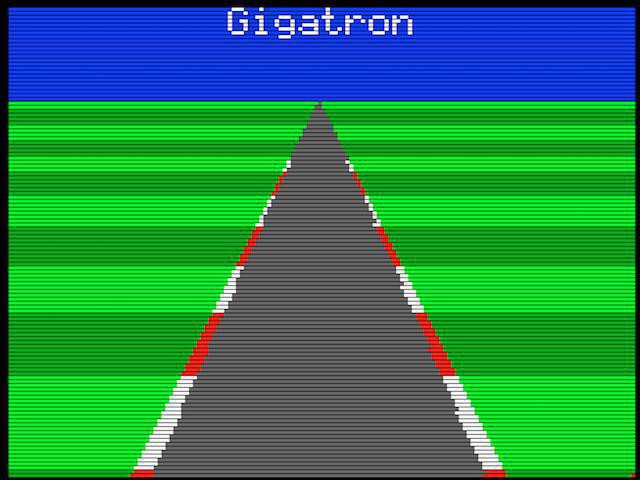
02/18/2018 at 14:28 • 0 commentsAfter 360 commits my coding frenzy has reached a conclusion: ROM v1 is feature complete! The kit will ship not with one but with two fast paced games: Snake and Racer. Sound improved and the serial loader is reliable, which is great for hacking and making more games. The fractal program now doubles as a clock, to give a valid excuse for keeping a unit on permanent display in the living room.
![]()
The unused ROM space is filled with three classic hires images from my previous projects. By packing 4 pixels in 3 bytes I got three images in where the ROM otherwise would only have space left for two.
This doesn't mean the to do list is empty, far from that: "make todo" lists 90 ideas I apparently still have in mind. But after 6 months of breadboard prototyping, 3 months of PCB design and 4 months of software hacking, this is a good point to shift focus again. For example, towards demonstrations, tutorials and documentation. Keep you posted.
![]()
-
Wrapping up the software for ROM v1
02/11/2018 at 14:46 • 2 commentsThe software to be included with the kit release later this month is nearly done. Just in time as we're now also waiting for the last parts shipment to arrive, expected in two weeks. When those are good we know if we can meet our target selling price and will announce it to those interested on the mailing list. All other parts are in house already, manuals printed, packaging ready and beta tests successfully completed. Our living rooms look like a warehouse now.
![]()
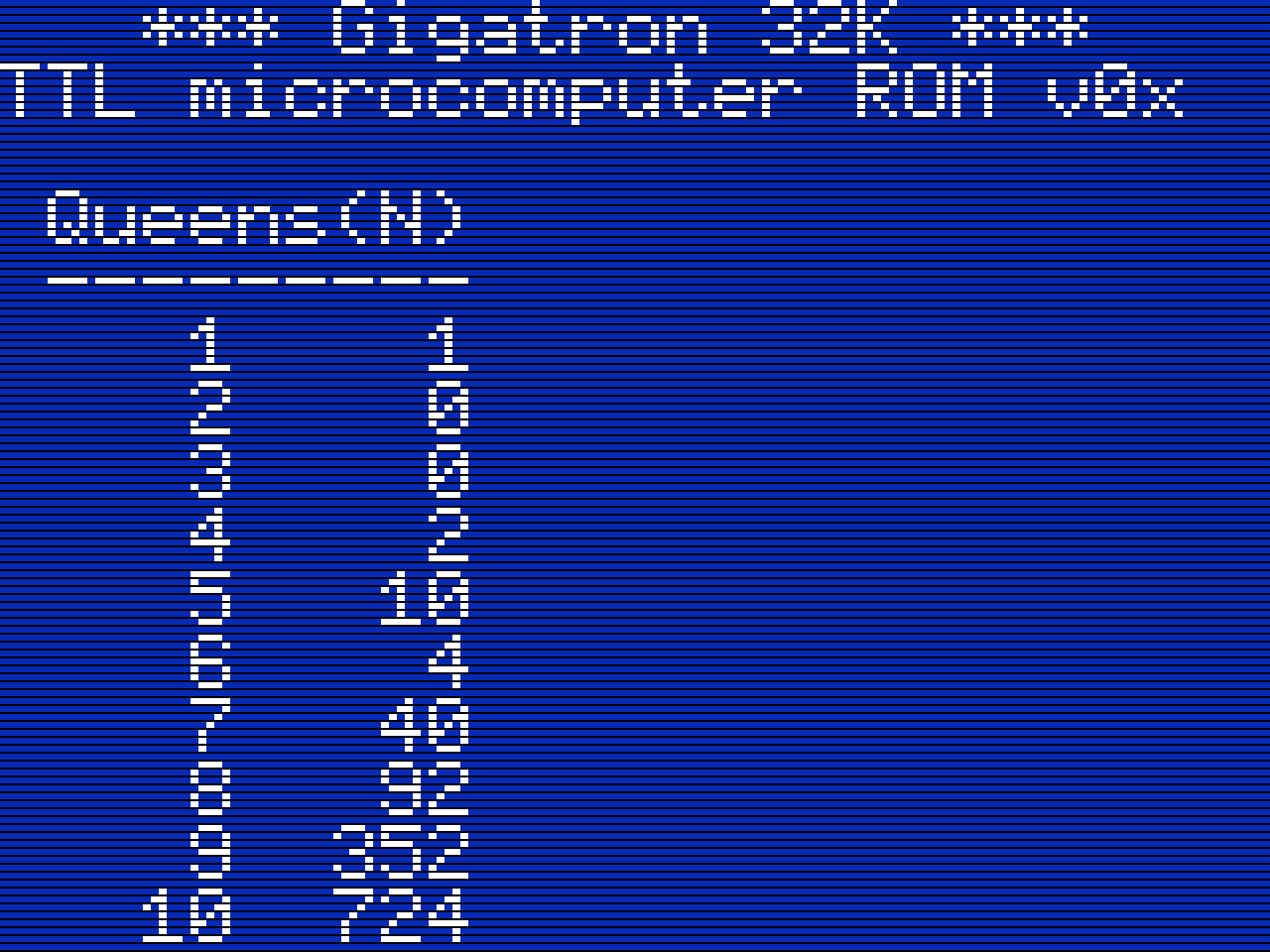
Of course the kit will ship with some demo applications built-in. My focus is for a part still on those, but equally important is that the programming core is stable and tested. For me it is crucial that the memory map is well-defined and the 16-bit interpreter is fully tested and useful. After all, the vCPU opcodes are jump offsets, so it will be impossible to fix any of that later while maintaining compatibility as well. Last week I found I had some unused space in the interpreter code page, so I added some new bit-wise logic instructions and support stack variables. Surprisingly, none of the applications I wrote so far needed those.
![]()
To test, I ported my old n-Queens solver. It exercises bitwise logic and recursion, so it is a good test for these new instructions. On the screenshot above you can see it gets the correct answers for the sequence. The solver uses 5 stack variables. That, plus one for the the return address, gives 12 bytes per invocation. With the stack living in the top half of the zero page, this means we can go 10 levels deep. The solver needs less than a minute to compute the list, or at about 850 recursions per second. [Edit: I just figured that it should be easy to go down to using 4 variables or 10 bytes, and with that up to 12 levels deep.]
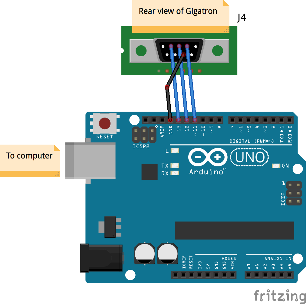
Although 8-bit assembly programs must be programmed in the EPROM, interpreted programs run from RAM. The built-in applications are of course stored in ROM also, but they are loaded into RAM first, so they use the ROM merely as a disk. Interpreted programs can also be loaded into RAM directly over the input port, and this is how you can program the Gigatron without using an EPROM eraser and programmer. For this I hook up the input port pins, that normally go to the game controller, to a simple Arduino. The Arduino can send data at the same rate as the horizontal sync. With some checksumming overhead, this boils down to exactly 28k8 payload bits per second. Much faster than loading C64 programs from tape back in the day... (3000 baud with speed loaders!)
The loader was the last part of the software that needed debugging with a scope.
-
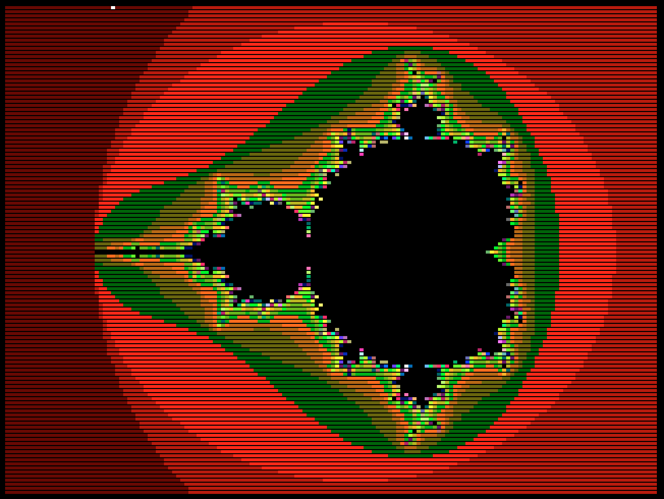
Mandelbrot from TTL
01/22/2018 at 00:33 • 7 commentsI got a bit stuck with the work I was planning for today, so I wrote something else to regain motivation: a fractal! Rendering takes a while (8242 seconds), being fully interpreted and lacking multiplication, and even without the "right-shift" operation you badly need for this. All those must be mimicked with slow high-level code using just addition and subtraction. [Edit: it takes 1127 seconds now with native code for "right-shift"]
![]()
It should be easy to speed the whole thing up a lot just by adding a right-shift assembly function. Next time... GCL source code:
{-----------------------------------------------------------------------+ | | | Mandelbrot fractal | | | +-----------------------------------------------------------------------} gcl0x { Plot the Mandelbrot set - 160x120 pixels and 64 colors - Faithful translation of mandelbrot.c pre-study - Use 16-bit vCPU math as 7-bit fixed point arithmetic (1.00 -> 128) - Implement multiplication in interpreter - Implement shift-right in interpreter as well - A bit slow (8242.655 seconds) XXX At the end change all to grey tones and redo XXX Redo at different sections XXX Tone for every pixel value } {-----------------------------------------------------------------------+ | RAM page 3 | +-----------------------------------------------------------------------} $0300: { Pretty accurate multiply-shift ((A*B)>>7), but it can be off by one } [def push {Extract sign and absolute values} 0 sign= C= {0}A- [if>0 A= 1 sign=] 0 B- [if>0 B= sign 1^ sign=] {Multiply} 7 shift= {Pending shift} $200 [do bit= -$4000 C+ [if<0 C C+ C= else {Shift prematurely in an attempt to avoid overflow} B ShiftRight! B= shift 1- shift=] {Add partial product} A bit- [if>=0 A= C B+ C=] bit ShiftRight! if<>0loop] {Shift} [do C ShiftRight! C= shift 1- shift= if>0loop] {Apply sign to return value} sign [if<>0 0 C- else C] pop ret ] MulShift7= { Calculate color for (X0,Y0) } [def push 0 X= XX= Y= YY= i= [do i 1+ i= 64^ if<>0 {Break after 64 iterations} {Mandelbrot function: z' := z^2 + c} X A= Y Y+ B= MulShift7! Y0+ Y= {Y = 2*X*Y + Y0} XX YY- X0+ X= {X = X^2 - Y^2 + X0} {Calculate squares} {X}A= B= MulShift7! XX= Y A= B= MulShift7! YY= -$200 XX+ YY+ if<0loop] {Also break when X^2 + Y^2 >= 4} i pop ret ] CalcPixel= {-----------------------------------------------------------------------+ |}\vLR>++ ret{ RAM page 4 | +-----------------------------------------------------------------------} $0400: [def push $7ff p= {Start of video (minus 1 to compensate for 1st step)} -323 X0= 3 DX= 161 Width= {Horizontal parameters} -180 Y0= 0 DY= 120 Height= {Vertical parameters} [do {Length of next segment, either horizontal or vertical} DX [if<>0 Width 1- Width= else Height 1- Height=] if>0 [do len= {Step in the fractal plane} X0 DX+ X0= Y0 DY+ Y0= {Matching step in video frame} DX [if<0 p 1- p=] DX [if>0 p 1+ p=] DY [if<0 -$100 p+ p=] DY [if>0 $100 p+ p=] 63 p. {White while busy here} {First check if we are inside one of the main bulbs for a quick bailout (Wikipedia) (x+1)^ + y^2 < 1/16} Y0 A= B= MulShift7! YY= X0 128+ A= B= MulShift7! YY+ 8- [if<0 0 else {q*(q + x - 1/4) < 1/4*y^2, where q = (x - 1/4)^2 + y^2} X0 32- A= B= MulShift7! YY+ {q} A= X0+ 32- B= MulShift7! tmp= tmp+ tmp= tmp+ tmp= {*4} YY- [if<0 0 else {Otherwise run the escape algorithm} CalcPixel! ]] p. {Plot pixel} len 1- if>0loop] DY tmp= DX DY= 0 tmp- DX= {Turn right} loop] pop ret ] CalcSet= {-----------------------------------------------------------------------+ |}\vLR>++ ret{ RAM page 5 | +-----------------------------------------------------------------------} $0500: { Stupid shift-right function } { XXX Better make a SYS extension for this } [def a= 0 b= $8000 a+ [if>=0 a= $4000 b+ b=] $c000 a+ [if>=0 a= $2000 b+ b=] $e000 a+ [if>=0 a= $1000 b+ b=] $f000 a+ [if>=0 a= $0800 b+ b=] $f800 a+ [if>=0 a= $0400 b+ b=] $fc00 a+ [if>=0 a= $0200 b+ b=] $fe00 a+ [if>=0 a= $0100 b+ b=] $ff00 a+ [if>=0 a= $0080 b+ b=] $ff80 a+ [if>=0 a= $0040 b+ b=] $ffc0 a+ [if>=0 a= $0020 b+ b=] $ffe0 a+ [if>=0 a= $0010 b+ b=] $fff0 a+ [if>=0 a= $0008 b+ b=] $fff8 a+ [if>=0 a= $0004 b+ b=] $fffc a+ [if>=0 a= $0002 b+ b=] a 2& [if<>0 b<++ ] b ret ] ShiftRight= {-----------------------------------------------------------------------+ |}\vLR>++ ret{ RAM page 6 | +-----------------------------------------------------------------------} $0600: { Main } [do CalcSet! 60 \soundTimer. {For debugging} loop] {-----------------------------------------------------------------------+ | End | +-----------------------------------------------------------------------} -
Hacker spaced
01/19/2018 at 23:54 • 0 commentsWhile waiting for the last parts to come in for the kit version (waiting can be so tedious), Walter and I had the privilege to be invited at two nice hacker spaces last month where we could talk about the project. So besides 34c3, we also visited RevSpace and Hack42 in the previous weeks. What a blast and what a great diversion from endlessly plowing through the kit details! Each time we met with plenty of great people with cool projects and had the chance the pick up many new ideas an suggestions.
The first talk at Hack42 was recorded and is on youtube. It is a bit over an hour where Walter talks through the entire design including Q&A. Enjoy!
-
930 logic gates
12/30/2017 at 23:41 • 0 commentsWhile playing Gigatron Snake at 34C3 we got asked: "how many gates are in there?". This isn't the first time someone has asked, so today I finally went through the TTL datasheets and counted little blocks from their logic diagrams. TL;DR: the CPU has 930 logic gates.
And because 34C3 is such an inspiring place, after one day of hacking those gates now happily animate this beginning of a Racer game:
![]()
Gate counting isn't as straightforward as it seems though. RAM and ROM are clear: they each have thousands of logic gates in their word line decoders alone, but those aren't part of the CPU proper. The clock isn't part of the CPU either, but that's just a couple of inverters. For decoding the game controller it isn't as clear cut: the kit version has a 74HC595 shift register which has roughly 80 gates. But only 10 buffer gates are really needed by the CPU and are directly controlled by it. I fact, on the breadboard version, the input chip is just a 10-gate 74LS244 non-inverting buffer. So I count that as one 10 for the CPU. I also didn't count the "extended output" register as part of the CPU because that is an extension on top of its primary output.
I did include all other gates that are in the IC packages: An unused module is in the count (there is one unused decoder in the control unit), as well as gates that are hooked to fixed inputs (L or H), even though all of those can be optimised away in VHDL. The 4-bit adders each have 4 non-inverting buffers internally that have no logic function, but I still include them. Furthermore, I count D-type flipflops as 5 gates, and SR-types as 4. Still, the total gate count of 930 is a lot lower than I would have guessed.
-
Tail chasing its head
12/23/2017 at 12:36 • 0 commentsTo make 64 colors, every pixel occupies 6 bits of a byte in RAM. The two high bits can have arbitrary values as they are masked by the pixel burst loop. This opens up all kinds of tricks. For example, they can encode play field information for a game: where there are walls, independent of their color. Here I use these bits in the snake segments: they keep track of direction so the tail can follow the head. Like invisible breadcrumbs. Up/down/right/left just needs 2 bits...
-
SYS calls for accelerating interpreted programs
12/18/2017 at 13:04 • 0 commentsThe virtual CPU or interpreter is now complete. At least, its code page is full, even overflowing a bit, and nothing can be added without removing something else. It has 25 opcodes, the last added is SYS. This is an escape: with SYS the application can jump to arbitrary native code. Here I test this capability in the "clear screen" loop, right at the beginning of the recording.
Without acceleration, clearing the screen pixel by pixel with interpreted code takes more than 2 seconds. Here the application uses a SYS call that clears 8 pixels at a time. The result is that the screen now clears in 200 ms. Nice proof of concept.
Restrictions apply if you don't want to break the video timing: the callee must be timing-aware and cooperate with the interpreter loop. But it can run for longer than a regular vCPU instruction (these are 28 cycles max) and the code can do whatever it wants, as long as it completes in the available time slice on the scan line. In reality this means that SYS calls can last for up to 146 cycles. If they need more cycles, they could still use some trickery and restart themselves by messing with the virtual program counter... They are "parasitic" after all.
Another novelty is that this recording is not from an actual Gigatron! Martin @ the talkchess forum has made an incredible visualisizer for the project. I didn't get it running with the Mac binary, but it runs ok with Wine. Emulation in emulation in emulation, but it can still keep up with real time if you use "Run sketch (JIT)". Amazing.
There is some latency with the sound, but that is fine. This tool already saved me a tons of EPROM burning cycles. For the real experience, just use a real Gigatron...
P.S: The Christmas card is there to give my phone something to focus on. Without it the recording is blurry.
-
Gigatron! The TTL computer as a kit
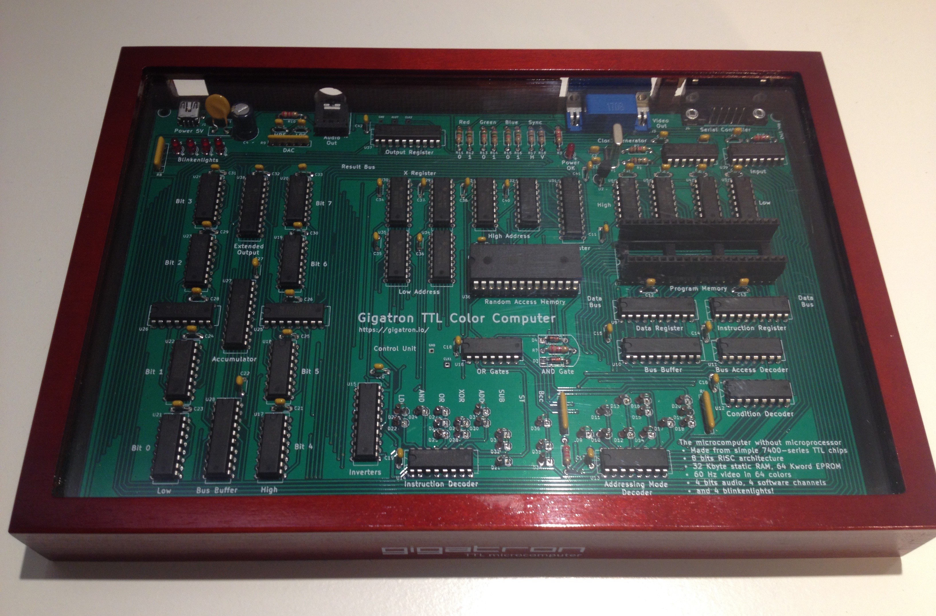
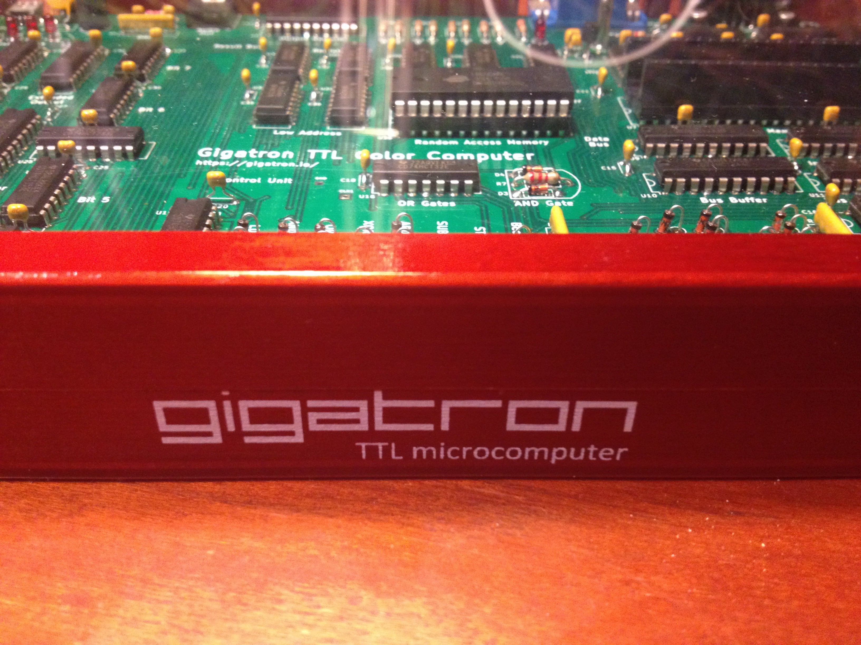
12/06/2017 at 21:03 • 2 commentsSome months ago my good friend Walter has silently joined the project. The reason is that I receive a lot of enthusiasm whenever I show this to friends, to the point where one is already seriously trying to write a chess program for it. So we decided to take this one step further and upgrade this to a build-it-yourself soldering kit. Today we received the first samples for the enclosure, custom designed for this computer.
![]()
With a new phase comes a new name. Neither of us really liked the "Chipper" working title I used before, so the kit version will be known as the "Gigatron TTL microcomputer". I couldn't possibly do this all by myself, so I'm super happy that Walter has stepped in.
This retro-computer is something to build, play with but also look at, so we plan to offer it as complete as possible, except for the soldering you will have to do yourself. So it will include all the 74xx-TTL chips, RAM, ROM, sockets, capacitors, diodes, resistors, LEDs, supervisory circuit, jacks, a game controller, a nice mahogany coloured wooden enclosure with plexiglass viewing window, one or two built-in video games and a mini-USB cable for power. Not all details are finalised yet: the photo is a prototype and we will still change some things we don't like. We think we can target the 150-180 euro price range (hopefully below 200 dollars), provided there is sufficient interest. For reference, getting to the first PCB version set me back north of 500 euros, that is where I stopped counting, and that excludes the oscilloscope you need when designing something like this from scratch. And did I mention the 800 hours of research, trial and error? This is still just a private hobby project, so this kit will be something we will literally do from our living rooms. We figure that if we do a few dozen units that would push the prices down a lot and at the same time not take too much risk.
![]()
Of course a kit isn't the same as a one-off project, and Walter has worked tirelessly on morphing the project towards something that can be reliably soldered together in 3 to 4 hours. All components are now through-hole components and sourced from proper sources (not scavenged from e-bay). Walter has written a supercool manual that includes intermediate tests, a circuit diagram and even soldering instructions and tips for novices. Although there are 144 components on the board (many capacitors and diodes), I feel it will still be a beginner's level kit because of the spacing and all through-hole components. All you need is a soldering iron, solder, a multimeter, some pliers and a rainy Sunday afternoon. If you can make Oscar's PiDP-8, then you can make this also.
For those interested in this kit, you can subscribe to our mailing list. We will use this mailinglist only to announce when we are comfortable to accept orders, know the exact pricing and have some kits ready to ship. Subscribing to the mailing list doesn't imply any obligation to buy: it is just a way to keep informed of when we are ready and you can easily delist as well. We expect we will be ready near the end of January. It will then also be clear what the final kit looks like, what the built-in software can do, etc.For those interested in this kit, check out our website: gigatron.io
Gigatron TTL microcomputer
Just because! A home computer without microprocessor


