Marcel van Kervinck
-
16-bit subtraction and ROM tables
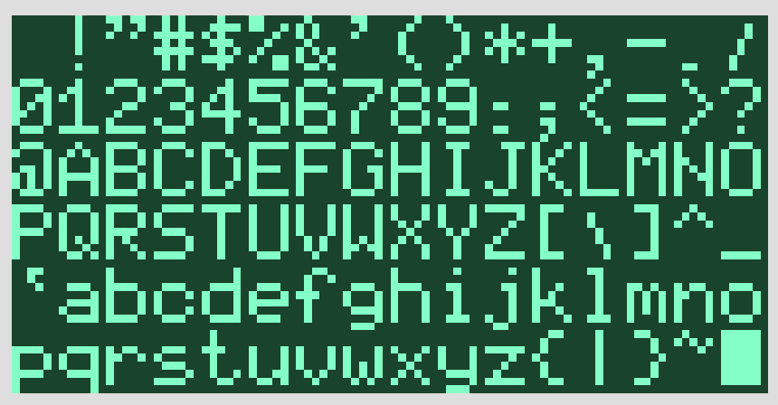
12/05/2017 at 20:37 • 0 commentsTwo small steps in software land: With 16-bit subtract we can bounce a ball properly. With ROM tables we can finally render the 5x8 font I designed some time ago. (In the video below I forgot to add letter spacing, so the characters are all smashed together.)
16-bit subtraction turned out to be a bit harder than I hoped for. The difficulty is that without a status register you must somehow reconstruct the carry in software. This boils down to ugly bit fiddling with nasty edge cases, and is frustrating, knowing that the minimalistic hardware has just thrown the same carry away. But it can be done and needs to be solved just once. The interpreter can now do it at the same speed as 16-bit addition: 28 cycles including interpreter overhead.
For the more time-critical sound oscillators, they run in every horizontal blank, I use a much faster 15-bit scheme (7+8), reserving 1 bit in the lower byte for carry. That works, but for the application interpreter I want proper math.
We now also have ROM tables accessible from within the interpreter. This means that it becomes easier to stuff lots of data and programs in ROM, and load any of it into RAM whenever needed and without disturbing the video loop.
Two nice steps towards a useful application environment.
-
Game compiler
11/30/2017 at 20:50 • 2 commentsThe inner interpreter decouples the harsh video timing from the application code. It runs whenever the video/audio/input handling has nothing to do, typically during vertical blank, and in every 4th scanline of the visible video. It reads instructions from RAM and dispatches to their native implementation. It works very much like SWEET16 on the Apple II, except that it also tracks their duration: when there is not enough time left for another instruction, it re-syncs with the video timing and returns control. To make programming easier, I wrote a simple offline compiler that provides a compact text notation with block structure, "if", "loop" etc.. Here is the beginning a game made in this:
-
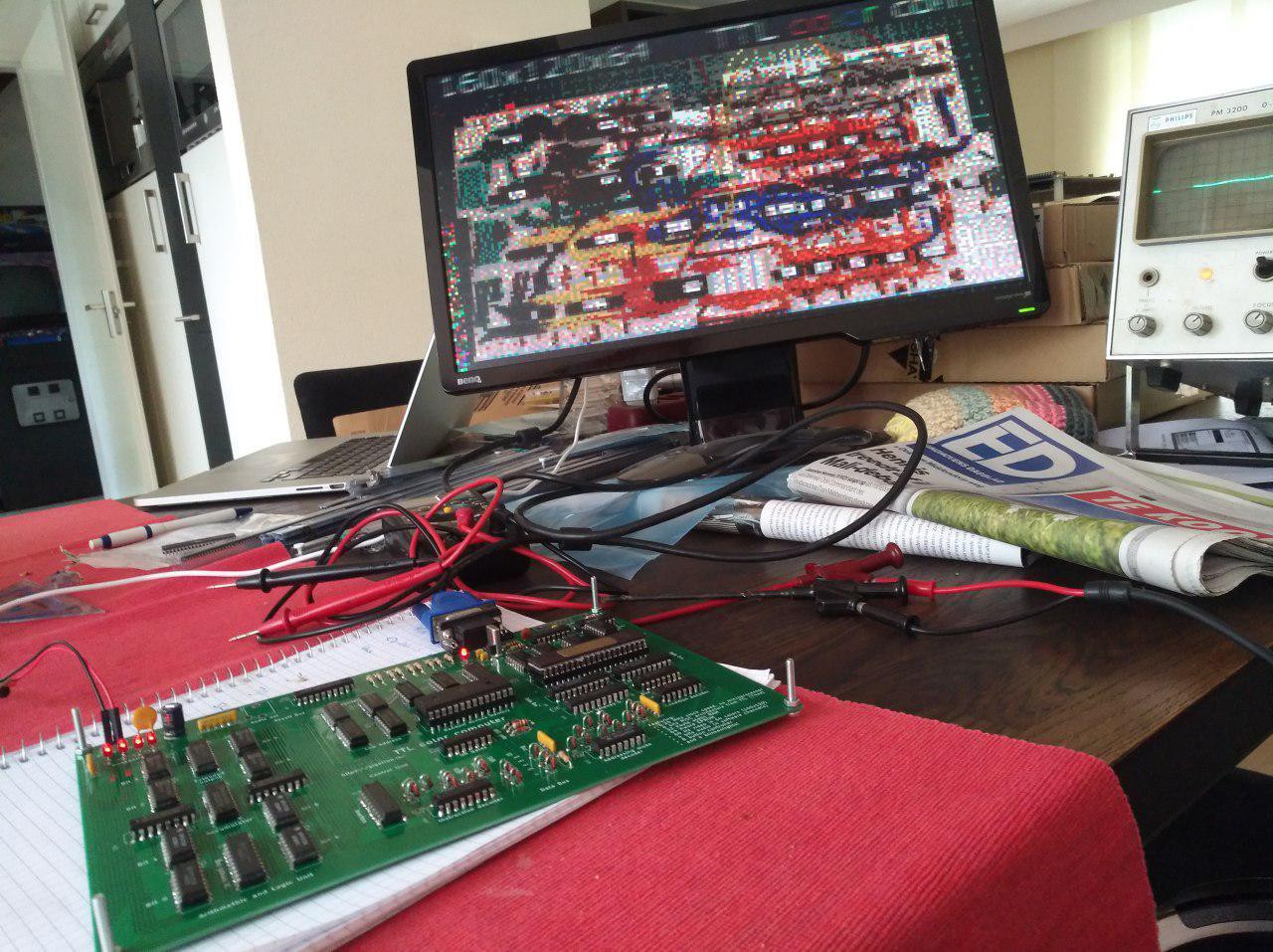
Moving up the ladder of abstraction
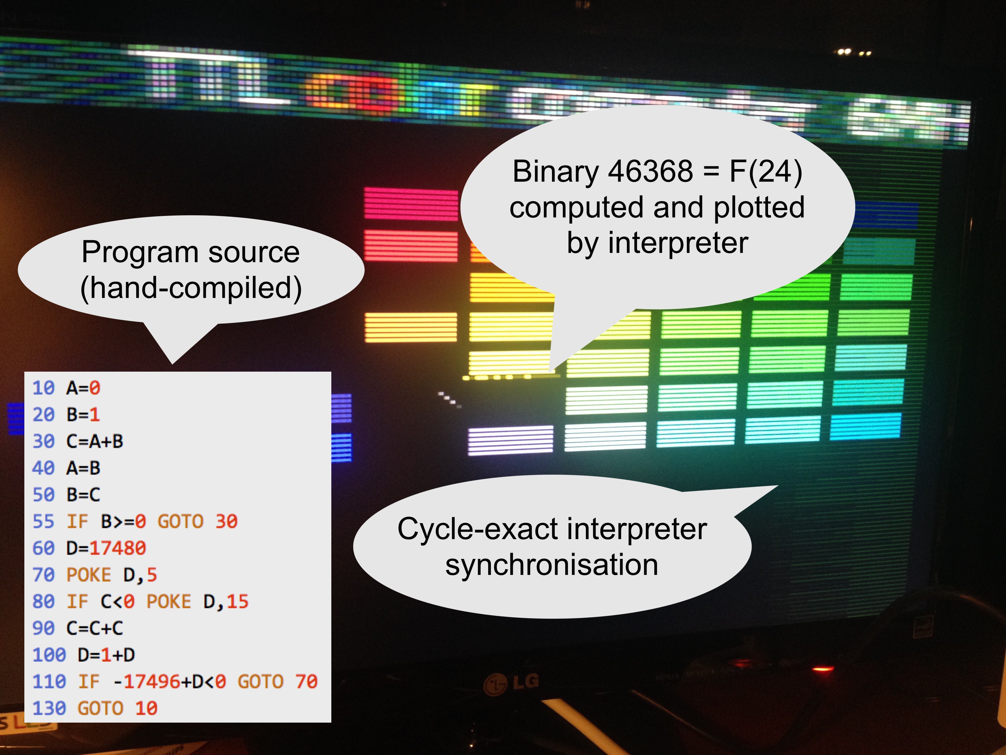
11/12/2017 at 17:54 • 0 commentsThis photo captures the inner application interpreter's first sign of life. Very early this morning, or late last night, the virtual CPU ran its first program. It calculated the largest 16-bit Fibonacci number to be 1011010100100000 and plotted that in the middle of the screen. The video loop was still playing the balls and bricks game, unaware of what was happening, but sometimes the ball bounces off the 16-bit result.
![]()
The interpreter is the virtual CPU that makes it possible for mere mortals to write applications without worrying about the arcane video timing requirements.
For this test I hand-compiled the BASIC program into interpreter code and preloaded it into RAM. Shown here is the interpreter running during every 4th visible VGA scan line. It dispatches instructions and keeps track of their duration until it runs out of time for the next sync pulse. It can't stream pixels at the same time so these lines render black. I don't mind the bonus retro look at all.
With this the system undergoes quite a metamorphosis:
- The TTL computer: 8-bits, planar RAM address space, RISC, Harvard architecture, ROM programmable
- The inner virtual CPU: 16-bits, (mostly) linear address space, CISC, Von Neumann architecture, RAM programmable
A typical interpreter instruction takes between 14 and 28 clock cycles. The slowest is 'ADDW' or 16-bits addition. This timing includes advancing the (virtual) program counter and checking the elapsed time before the video logic must take back control. It also needs a couple of branches and operations to figure out the carry between low byte an high byte. That is the price you pay for not having a status register. But is that slow? Lets compare this with 16-bit addition on the MOS 6502, which looks like this:
CLC     ;2 cycles
LDA $10 ;3 cycles
ADC $20 ;3 cycles
STA $30 ;3 cycles
LDA $11 ;3 cycles
ADC $21 ;3 cycles
STA $31 ;3 cycles
        ;total 20 cycles or 20 µsec
The TTL computer executes its equivalent ADDW instruction in 28/6.25MHz = 4.5 µsec.
We should be able to get out roughly 60k virtual instructions per second while the screen is active, or 300k per second with the screen off. So I believe the interpreter's raw speed is quite on par with the microprocessors of the day. The system itself of course loses effective speed because its hardware multiplexes the function of multiple components: CPU, video chip and audio chip are all handled by the same parts. And to make things worse, the computer "wastes" most of its time redrawing every pixel row 3 times and maintaining a modern 60Hz frame rate. PAL or NTSC signals of the day were 4 times less demanding than even the easiest VGA mode.
Next step at the software front is finding a good notation for the source language.
On the hardware side, there is some progress on a nice enclosure. I hope to have a preview soon.
-
Bouncing ball and pad
10/30/2017 at 01:44 • 0 comments -
Interaction
10/16/2017 at 20:50 • 0 commentsWith the instruction set, video, sound and blinkenlights already checked, the last remaining unknown is the input. I will be using a simple NES-type of controller for the games. Unlike the simpler Atari joysticks these controllers have a serial interface. In this video you see the computer read the input once during every scanline in vertical blank, and render the received value in binary somewhere in the middle of the screen.
The controller needs sync pulses from the computer. For simplicity I feed it with the VGA vSync and hSync signals. The software loop already generates these anyway. Then on the receiving end I decode the controller's single data line with a 74HC595 shift register, which in turn connects to the computer's data bus. The 74HC595 is also designed to work with two sync signals, but I didn't bother and hooked up both pins to hSync. With that, 60 times per second the controller state flows through the shift register at a rate of one bit per scanline. Using the in bus mode the software can read its contents. It just needs to catch it at exactly the right time otherwise the buttons get confused. But the timing is measured in scanlines, and this computer races pixels, so no sweat there.
The code running in the video above is this:
address
|    encoding
|    |     instruction
|    |     |    operands
|    |     |    |
V    V     V    V
016f 0043  ld   $43          # Calculate which Y position we want to draw
0170 b508  suba [$08],y
0171 1014  ld   $14,x        # Start at fixed X position (20)
0172 dc00  st   $00,[y,x++]  # Draw black pixel and advance X
0173 c313  st   in,[$13]     # Read controller input
0174 0001  ld   $01          # Set mask to bit 1
0175 c214  st   [$14]
0176 2113  anda [$13]        # Is this bit On or Off?
0177 f07a  beq  $7a          # (See previous blog post on this idiom)
0178 fc7b  bra  $7b
0179 000f  ld   $0f          # On: yellow
017a 0004  ld   $04          # Off: dark green
017b de00  st   [y,x++]      # Draw pixel and advance X
017c 0114  ld   [$14]
017d f475  bge  $75          # Shift mask and loop over all bits
017e 8200  adda ac
017f dc00  st   $00,[y,x++]  # Draw a final black pixel
With this last hurdle taken, the TTL microcomputer is complete: we have video in 64 colors, 4 channels of sound and we have input to make it interactive.
Everything is now ready to start writing games.
-
Pipelining and the single-instruction subroutine
10/15/2017 at 20:13 • 2 commentsPipelining basics
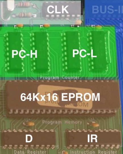
Our computer uses simple pipelining: while the current instruction is stable in the IR and D registers and executing, the next instruction is already being fetched from program memory.
![]()
This makes high speeds possible, but comes with an artefact: when a branch is executing, the instruction immediately behind the branch has already been fetched. This instruction will be executed before the branch takes effect and we continue from the new program location. Or worded more properly: the effect of branches is always delayed by 1 clock cycle.
When you don't want to think about these spurious instructions you just place a nop (no-operation) behind every branch instruction. Well, our instruction set doesn't have an explicit nop, but ld ac will do. My disassembler even shows that instruction as a nop. The Fibonacci program uses this all over:
address
|    encoding
|    |     instruction
|    |     |    operands
|    |     |    |
V    V     V    V
0000 0000  ld   $00
0001 c200  st   [$00]
0002 0001  ld   $01
0003 fc0a  bra  $0a
0004 0200  nop
0005 0100  ld   [$00]
0006 c202  st   [$02]
0007 0101  ld   [$01]
0008 c200  st   [$00]
0009 8102  adda [$02]
000a c201  st   [$01]
000b 1a00  ld   ac,out
000c f405  bge  $05
000d 0200  nop
000e fc00  bra  $00
000f 0200  nop
If you don't want to waste those cycles, usually you can let the extra slot do something useful instead. There are two common folding methods. The first is jumping to a position one step ahead of where you want to go, and copy the missed instruction after the branch instruction. In the example above, look at the branch on address $000e, it can be rewritten as follows:
000e fc01  bra  $01   # was: bra $00
000f 0000  ld   $00   # instruction on address 0
The second method is to exchange the branch with the previous instruction. Look for example at the branch on address $0003. The snippet can be rewritten as follows:
0002 0001  bra  $0a   # was: ld   $01
0003 fc0a  ld   $01   # was: bra  $0a
0004 0200  nop        # will not be executed and can be removed
One of these folding methods is often possible, but not always. Needless to say, applying this throughout can lead to code that is both very fast and very difficult to follow. Here is a delay loop that runs for 13 cycles:
address
|    encoding
|    |     instruction
|    |     |    operands
|    |     |    |
V    V     V    V
0125 0005  ld   $05 # load 5 into AC
0126 ec26  bne  $26 # jump to $0126 if AC not equal to 0
0127 a001  suba $01 # decrement AC by 1
This looks like nonsense: the branch is jumping to its own address and the countdown is in the instruction behind. But due to the pipelining this is just how it works.
Advanced pipelining: lookup tables
The mind really boggles when the extra instruction is a branch itself. But there is a useful application for that: the single-instruction subroutine, a technique to implement efficient inline lookup tables.
Here we jump to an address that depends on a register value. Then immediately following we put another branch instruction to where we want to continue. On the target location of the first branch we now have room for "subroutines" that can execute exactly one instruction (typically loading a value). These subroutines don't need to be followed by a return sequence, because the caller conveniently just provided that... With this trick we can make compact and fast lookup tables. The LED sequencer from yesterday's video uses this to implement a state machine:
address
|    encoding
|    |     instruction
|    |     |    operands
|    |     |    |
V    V     V    V
0105 0009  ld   $09    # Start of lookup table (we stay in the same code page $0100)
0106 8111  adda [$11]  # Add current state to it (a value from 0-15)
0107 fe00  bra  ac     # "Jump subroutine"
0108 fc19  bra  $19    # "Return" !!!
0109 0010  ld   $10    # table[0] Exactly one of these is executed
010a 002f  ld   $2f    # table[1]
010b 0037  ld   $37    # table[2]
010c 0047  ld   $47    # table[3]
010d 0053  ld   $53    # table[4]
010e 0063  ld   $63    # table[5]
010f 0071  ld   $71    # table[6]
0110 0081  ld   $81    # table[7]
0111 0090  ld   $90    # table[8]
0112 00a0  ld   $a0    # table[9]
0113 00b1  ld   $b1    # table[10]
0114 00c2  ld   $c2    # table[11]
0115 00d4  ld   $d4    # table[12]
0116 00e8  ld   $e8    # table[13]
0117 00f4  ld   $f4    # table[14]
0118 00a2  ld   $a2    # table[15]
0119 c207  st   [$07]  # Program continues here
At runtime 6 instructions get executed: ld, adda, bra, bra, ld, st
(Note: The values in this example are not important. If interested: the high 4 bits are the new state in the state machine, and the low 4 bits are the 4 LED outputs. This snippet of code implements the startup sequence and moving scanner lights from the video.)
Hyper advanced pipelining: the ternary operator
The pipeline gives a nice idiom for a ternary operator. With that I mean constructs like these:
V = A if C else B       # Python
V = C ? A : B           # C
if C then V=A else V=B  # BASIC
The simple way to do this is as follows:
        ld  [C]
        beq done
        ld  [B]
        ld  [A]
done:   st  [V]
The folding methods are already applied. In the false case (C == 0), B gets stored and this takes 4 cycles. In the true case B gets loaded first but is then replaced with A, which gets stored. This takes 5 cycles.
If you are in a time-critical part, such as in the video loop of this computer, this timing difference is quite annoying because we have to keep each path exactly in sync. The naive way to make both branches equally fast is something like this:
        ld  [C]
        beq label
        ld  [B]
        bra done
        ld  [A]
label:  nop
        nop
done:   st  [V]
Now each path takes 6 cycles and doesn't mess up our timing. But it is clumsy and inelegant. Fortunately there is a much better way, again by placing two branch instructions immediately in sequence:
        ld  [C]
        beq label
        bra done
        ld  [A]
label:  ld  [B]
done:   st  [V]
There we are: 5 cycles along each path! Figuring this one out is left as an exercise to the reader.
Note: This idiom has become so common in the Gigatron kernel that we don't bother to define labels for it any more. In the source code you therefore see something like this instead:
        ld  [C]
        beq *+3
        bra *+3
        ld  [A]
        ld  [B]
        st  [V]
Dummy instructions
A final frequent "use" of the branch delay slot is when we care more about space than about speed. In those cases, we can sometimes squeeze out a word.
For example, vCPU uses that in a couple of places. For technical reasons, each vCPU instruction must take an even number of cycles. That means that sometimes a nop() has to be inserted anyway. Instead of adding the nop(), we can also have the function overlap with the first instruction of the next routine.
We can see this applied in the overlap between LDI and LDWI:
              0318 00f6  ld   $f6         1469  ld(-20//2)
              0319 fc01  bra  NEXT        1470  bra('NEXT')
                                          1471  #dummy()
                                          1474  label('LD')
LD:           031a 1200  ld   ac,x        1475  ld(AC,X)
              031b 0500  ld   [x]         1476  ld([X])
Obviously, this only works if that instruction doesn't do something that interferes with the operation.
-
Anatomy of an 8-bits TTL microcomputer
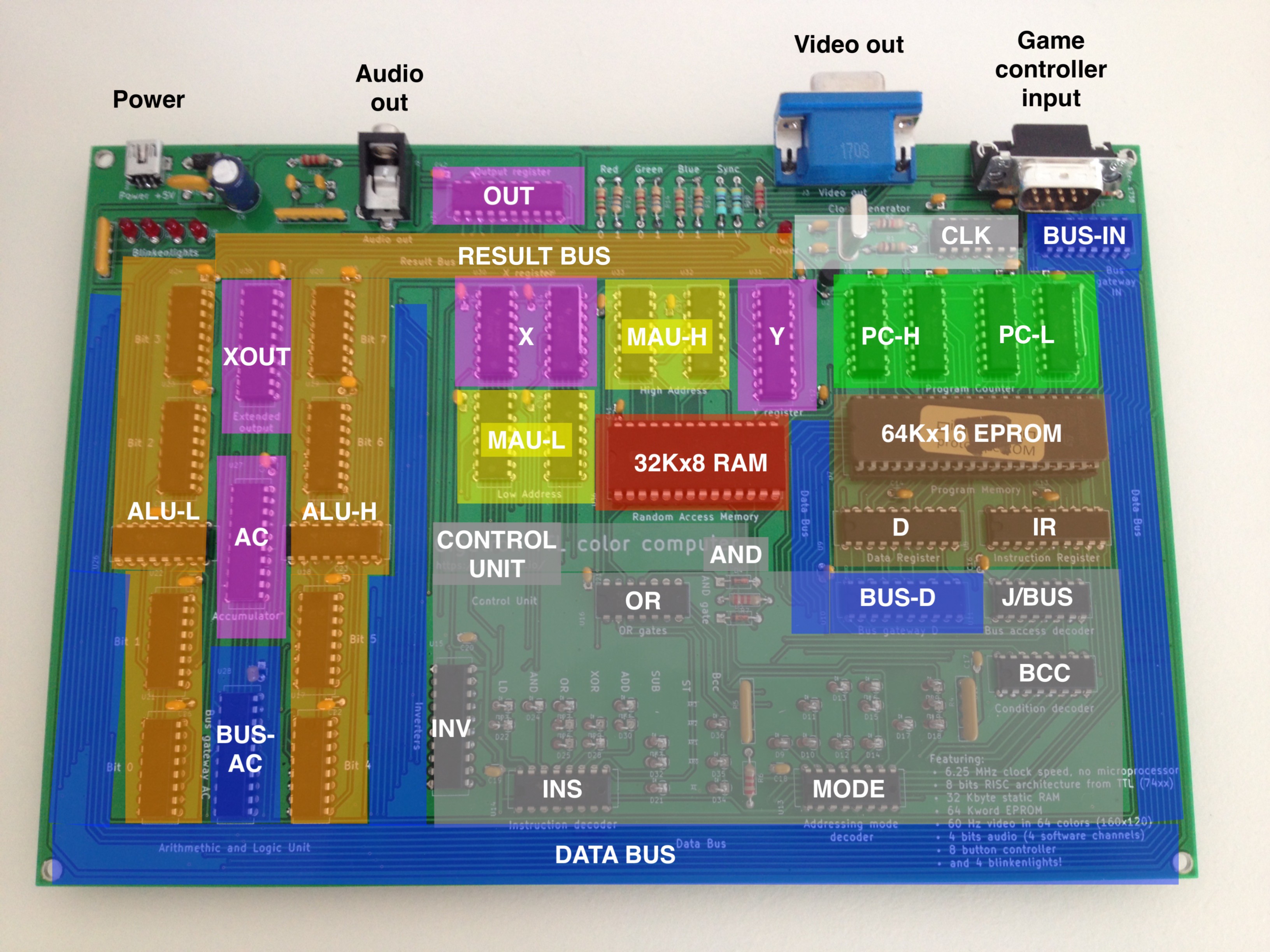
10/15/2017 at 11:45 • 0 comments36 simple TTL chips for CPU, output and clock. A static RAM, an EPROM and a hand full of passives to make the system complete. I kept the unit coloring as in the block diagram, which in turn follows the Velleman wire colors on the breadboard version.
![]()
-
G-major and scanner lights
10/15/2017 at 00:32 • 0 commentsAfter software-generated video we now also have a software generated sound playing. In four channels! And the blinkenlights are blinking, slowly getting there...
Sound and LEDs are driven by the same 8-bit extended output register which receives updates during the horizontal video sync pulse. I have split its output into 4 bits for sound and 4 bits for the LEDs. Every VGA scan line one of four independent software oscillators gets updated by the software. Every four scan lines their sum goes through the R2R DAC into the 3.5mm audio jack to the PC speakers that I picked up from a thrift store. Here I initialised the channels to play a G-major chord. I don't have a music sequencer yet, so it is just one chord. But as you can see there is a LED sequencer in place already, the music sequencer will be similar.
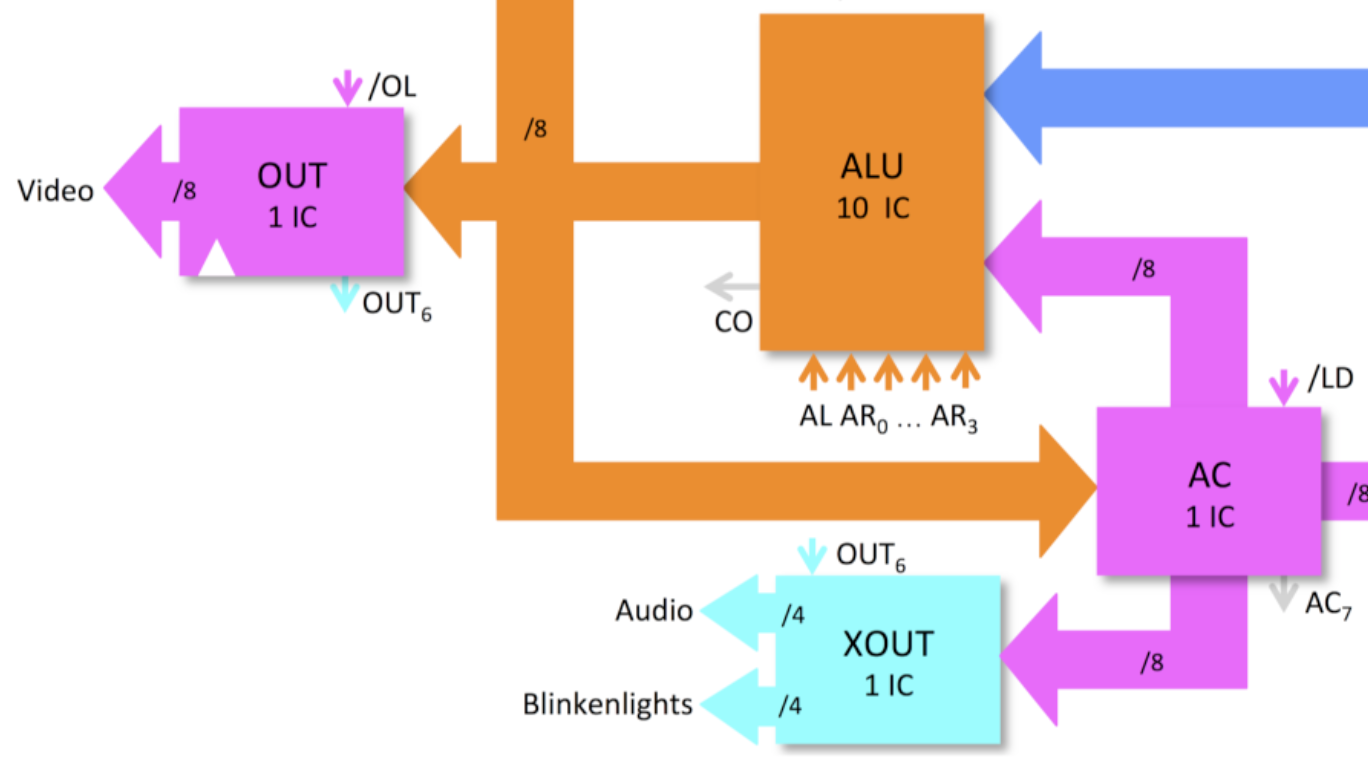
The extended output XOUT is just 1 extra 74273 chip that is not directly visible to the processor. It lurks on the horizontal sync for its clock and it gets its data from the accumulator. So typically it takes 3 instructions to update it. Here is how I switch off all LEDs immediately after power-on:
address
|    encoding
|    |     instruction
|    |     |    operands
|    |     |    |
V    V     V    V
0000 0000  ld   $00     # Clear AC
0001 1880  ld   $80,out # Negative flank (bit 6)
0002 18c0  ld   $c0,out # Positive flank (bit 6). This causes XOUT to be updated.
It is a simple way to get 8 additional output pins. Here it is in the block diagram:
![]()
Hardware-wise this is the second PCB build, the difference with the first board being the logic family soldered onto it: The breadboard and first PCB were using the classic 74LS series of TTL, while this board is using 74HCT chips for a change. They are completely compatible, only the video resistors needed somewhat higher values because the 74HCT outputs are always near the rails. As a result of this change, this specific board uses a lot less power: Just 80 mA for the FETs vs. 530 mA for the bipolar versions (or <0.5 Watts vs. >2.5 Watts). It should run for days on that battery pack. The difference between 1983s technology vs. 1971s...
-
Retro font
10/13/2017 at 18:50 • 4 commentsThe resolution is good for games but 8x8 characters will still be huge. It is amazing how much variety there is among the available 5x7 and 5x8 fonts. I just have to add another one.
![]()
Tool chain: Excel --> Print as PDF --> Preview --> Save as PNG --> ImageMagick --> Scale and save as RGB --> Python. This was simpler 30 years ago.
-
Working PCB version
10/04/2017 at 16:33 • 2 commentsThe breadboard TTL color computer has a PCB baby now. Her heart beats at 6.25 MHz. Here you see the little one sleeping and dreaming of her mom. Mother and baby are doing well. Father will be fine soon also.
![]()
Gigatron TTL microcomputer
Just because! A home computer without microprocessor