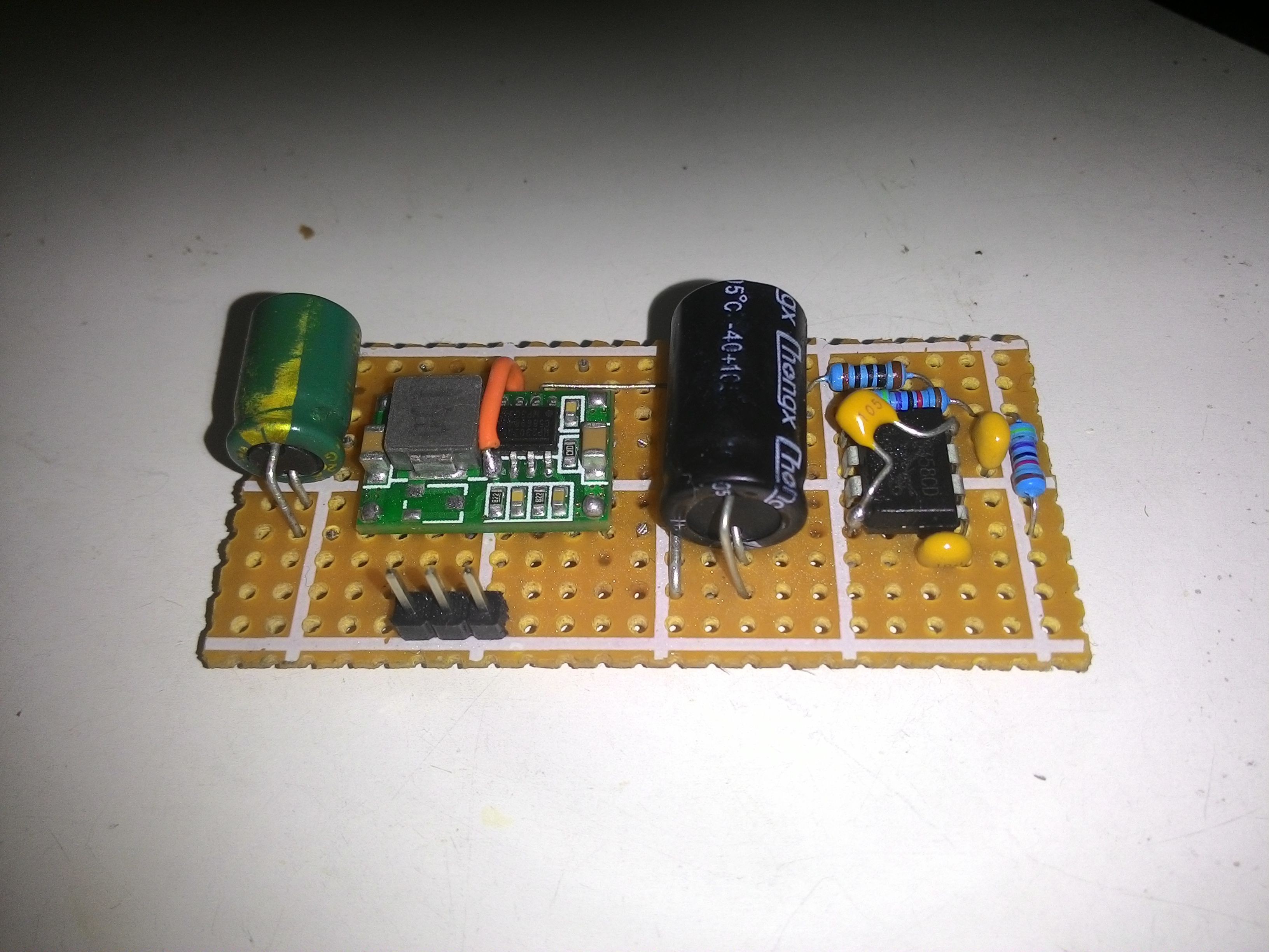
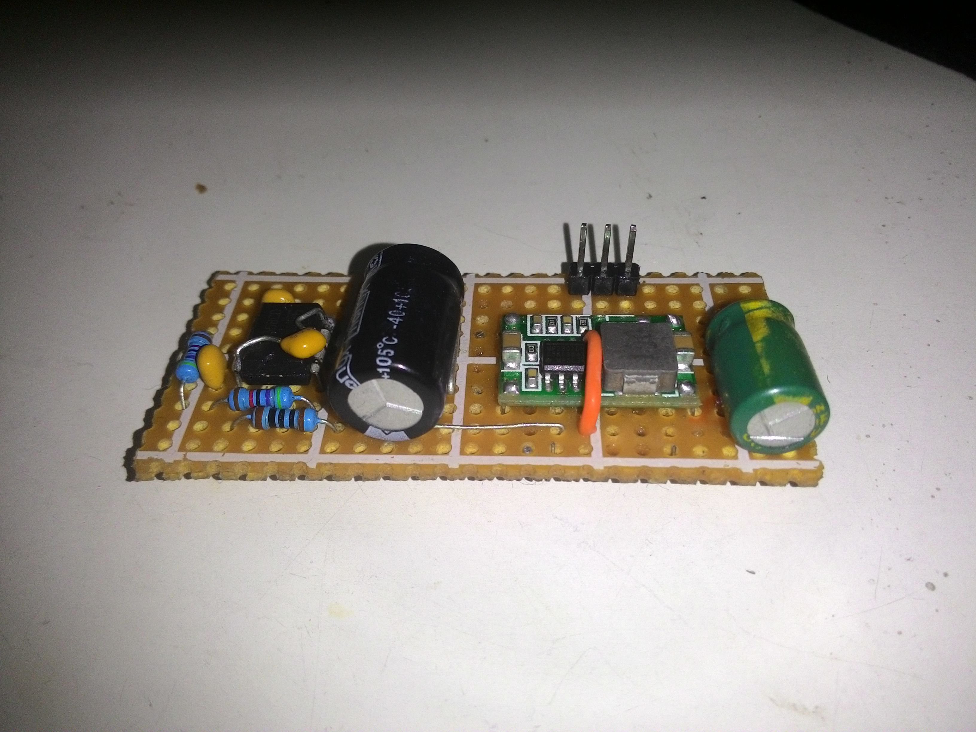
I finally made an improved version of the board. Main changes are:
-better pcb layout
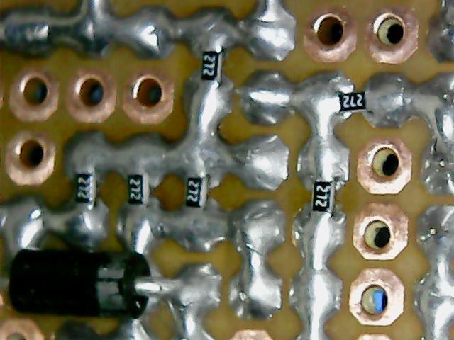
-the use of 0.05% resistor
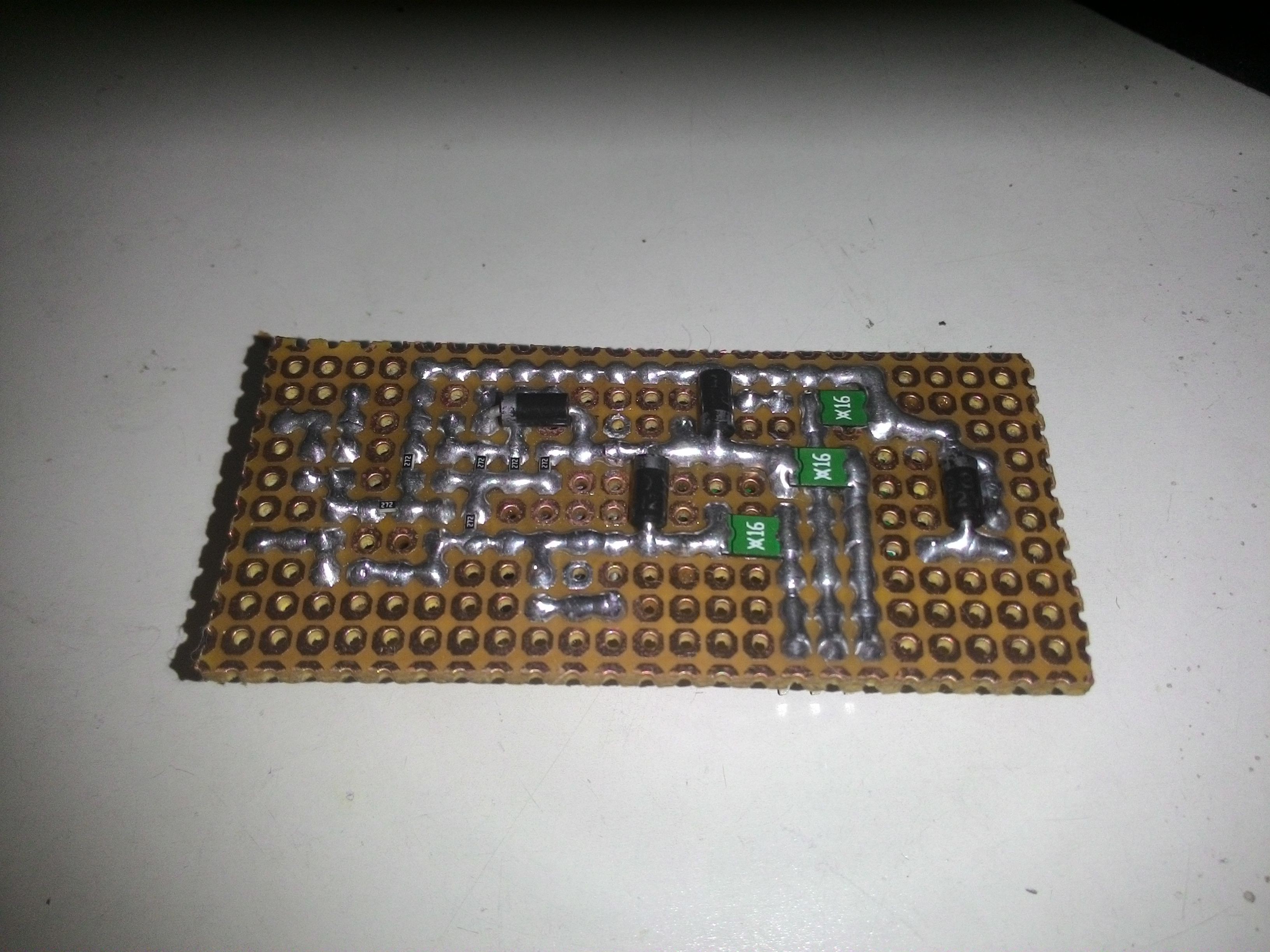
-reverse polarity protection (schottky diode)
-overcurrent protection (polyfuse)
I plan to include overvoltage protection (zener diode) in the future.
To my surprise, my 6000 counts multimeter (count at each 1mV) reports accuracy of 100%! :)
I know it is not true, maybe near 99.9%, but, that is the best resolution that I can get for now.
Front view:
Another view:
Bottom view:
Close-up of the smd 0.05% 2.7kR 0603 resistor on the 0.1" pitch perfboard:
Not only the accuracy improved, the balancing time also has improved:
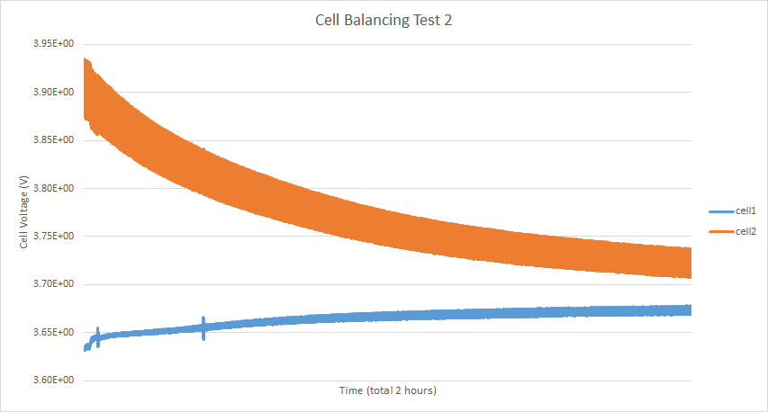
As shown in the plot, both of the cells approaches center-voltage a lot faster than the previous board. Notice that the charge in the orange cell gets transferred into the blue cell.
The charge time is dictated by the resistance of the balancing lead. I found that it takes longer for it to balance if the difference is smaller 100mV, i.e. getting 1 amp at 100mV needs 100 milliohms cable.
It is difficult for me to achieve that low resistance because of the high wire gauge that I have used as the balancing leads.
At the moment, I am waiting for reviews from endless-sphere forum. After I got enough positive reviews, I will proceed to send the pcb to be manufactured.
Discussions
Become a Hackaday.io Member
Create an account to leave a comment. Already have an account? Log In.